brake Peugeot Bipper 2011 - RHD (UK, Australia) Owner's Guide
[x] Cancel search | Manufacturer: PEUGEOT, Model Year: 2011, Model line: Bipper, Model: Peugeot Bipper 2011Pages: 180, PDF Size: 5.13 MB
Page 134 of 180
132
Towing a trailer
In certain cases of particularly arduous
use (towing the maximum load up a steep
slope in high temperatures), the engine
automatically limits its power. In this case,
automatic cutting off of the air conditioning
allows the engine power to be saved.
If the coolant temperature
warning lamp comes on, stop the
vehicle and switch off the engine
as soon as possible.
See the "Levels" section of chapter 7.
Tyres:
check the tyre pressures of the
towing vehicle (see the "Identification
markings" section of chapter 7) and of
the trailer, observing the recommended
pressures.
Brakes:
towing increases the braking
distance. Drive at a moderate speed,
change down early and brake gradually.
Side wind:
sensitivity to side wind is
increased. Drive smoothly and at a
moderate speed.
ABS:
the system only controls the vehicle,
not the trailer.
Rear parking sensors:
the sensors
will be deactivated automatically when
an genuine PEUGEOT towbar is used
(see the "Rear parking sensors" section of
chapter 3).
Towbar
We recommend the use of original
PEUGEOT towbars and their harnesses,
which have been tested and approved from
the design stage of your vehicle, and that
the fitting of this equipment is entrusted to a
PEUGEOT dealer or a qualified workshop.
If this equipment is not fitted by a PEUGEOT
dealer, it is essential that it is fitted using
the electrical pre-equipment located at
the rear of the vehicle and following the
manufacturer's instructions.
The operation of the rear parking sensors is
deactivated automatically when the trailer
cable connector is inserted in the towbar
socket.
When the trailer cable is removed, the rear
parking sensors are re-activated.
Distribution of loads
Distribute the load in the trailer so that the
heaviest objects are as close as possible
to the axle and the nose weight is close to
the maximum authorised without, however,
exceeding it. The air density decreases with
altitude, so reducing the performance of
the engine. The maximum towed load must
be reduced by 10 % for each 1 000 metres
of altitude. Refer to the "Technical data"
chapter for details of the weights and towed
loads applicable to your vehicle and also to
the administrative documents
(V5 registration document, ...).
Page 140 of 180
138
Changing a wheel
CHANGING A WHEEL
Parking the vehicle
As far as possible, park the vehicle on level,
stable and non-slippery ground.
Apply the parking brake, switch off the
ignition and engage first gear (on a hill).
It is imperative that you ensure that the
occupants get out of the vehicle and wait in
a safe location.
If possible, place a chock under the
wheel diagonally opposite the wheel to be
changed.
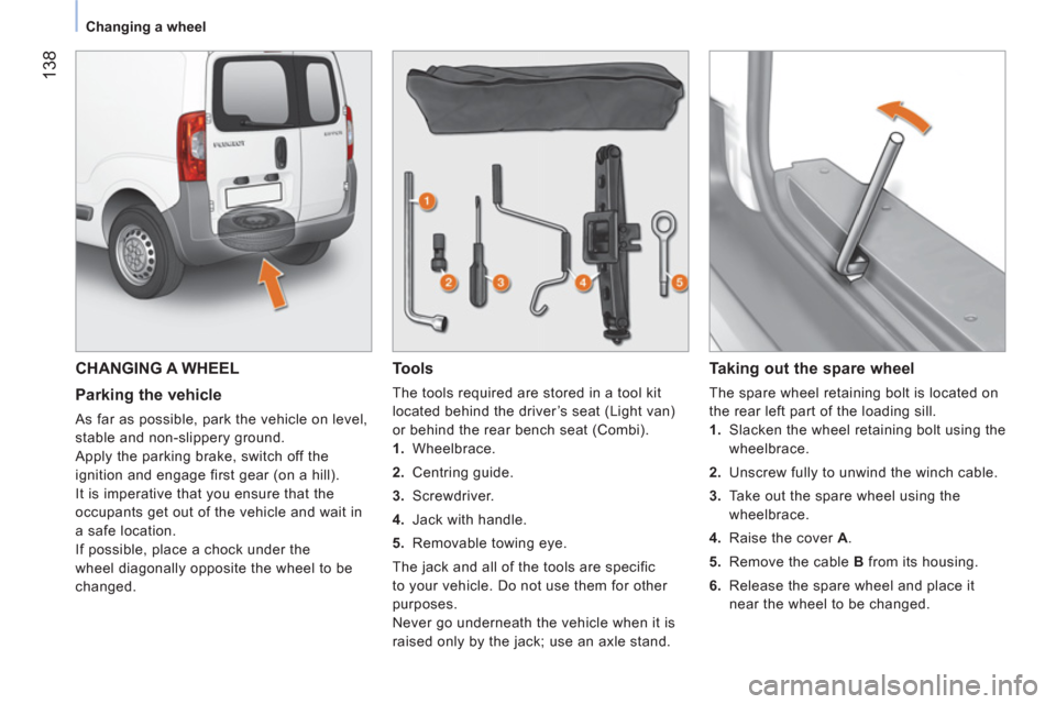
Tools
The tools required are stored in a tool kit
located behind the driver’s seat (Light van)
or behind the rear bench seat (Combi).
1.
Wheelbrace.
2.
Centring guide.
3.
Screwdriver.
4.
Jack with handle.
5.
Removable towing eye.
The jack and all of the tools are specific
to your vehicle. Do not use them for other
purposes.
Never go underneath the vehicle when it is
raised only by the jack; use an axle stand.
Taking out the spare wheel
The spare wheel retaining bolt is located on
the rear left part of the loading sill.
1.
Slacken the wheel retaining bolt using the
wheelbrace.
2.
Unscrew fully to unwind the winch cable.
3.
Take out the spare wheel using the
wheelbrace.
4.
Raise the cover A
.
5.
Remove the cable B
from its housing.
6.
Release the spare wheel and place it
near the wheel to be changed.
Page 141 of 180
7
QUICK HEL
P
Changing a wheel
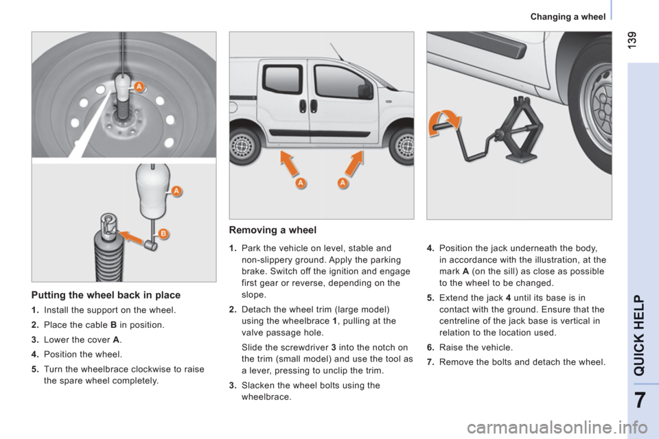
Removing a wheel
1.
Park the vehicle on level, stable and
non-slippery ground. Apply the parking
brake. Switch off the ignition and engage
first gear or reverse, depending on the
slope.
2.
Detach the wheel trim (large model)
using the wheelbrace 1
, pulling at the
valve passage hole.
Slide the screwdriver 3
into the notch on
the trim (small model) and use the tool as
a lever, pressing to unclip the trim.
3.
Slacken the wheel bolts using the
wheelbrace.
4.
Position the jack underneath the body,
in accordance with the illustration, at the
mark A
(on the sill) as close as possible
to the wheel to be changed.
5.
Extend the jack 4
until its base is in
contact with the ground. Ensure that the
centreline of the jack base is vertical in
relation to the location used.
6.
Raise the vehicle.
7.
Remove the bolts and detach the wheel.
Putting the wheel back in place
1.
Install the support on the wheel.
2.
Place the cable B
in position.
3.
Lower the cover A
.
4.
Position the wheel.
5.
Turn the wheelbrace clockwise to raise
the spare wheel completely.
Page 143 of 180
14
1
7
QUICK HEL
P
Changing a wheel
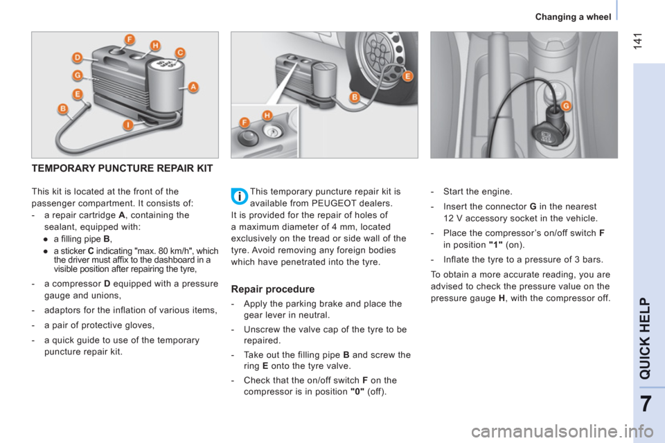
TEMPORARY PUNCTURE REPAIR KIT
This kit is located at the front of the
passenger compartment. It consists of:
- a repair cartridge A
, containing the
sealant, equipped with:
●
a fi lling pipe B
,
●
a sticker C
indicating "max. 80 km/h", which
the driver must affi x to the dashboard in a
visible position after repairing the tyre,
- a compressor D
equipped with a pressure
gauge and unions,
- adaptors for the inflation of various items,
- a pair of protective gloves,
- a quick guide to use of the temporary
puncture repair kit.
Repair procedure
- Apply the parking brake and place the
gear lever in neutral.
- Unscrew the valve cap of the tyre to be
repaired.
- Take out the filling pipe B
and screw the
ring E
onto the tyre valve.
- Check that the on/off switch F
on the
compressor is in position "0"
(off).
- Start the engine.
- Insert the connector G
in the nearest
12 V accessory socket in the vehicle.
- Place the compressor’s on/off switch F
in position "1"
(on).
- Inflate the tyre to a pressure of 3 bars.
To obtain a more accurate reading, you are
advised to check the pressure value on the
pressure gauge H
, with the compressor off. This temporary puncture repair kit is
available from PEUGEOT dealers.
It is provided for the repair of holes of
a maximum diameter of 4 mm, located
exclusively on the tread or side wall of the
tyre. Avoid removing any foreign bodies
which have penetrated into the tyre.
Page 148 of 180
14
6
Changing a bulb
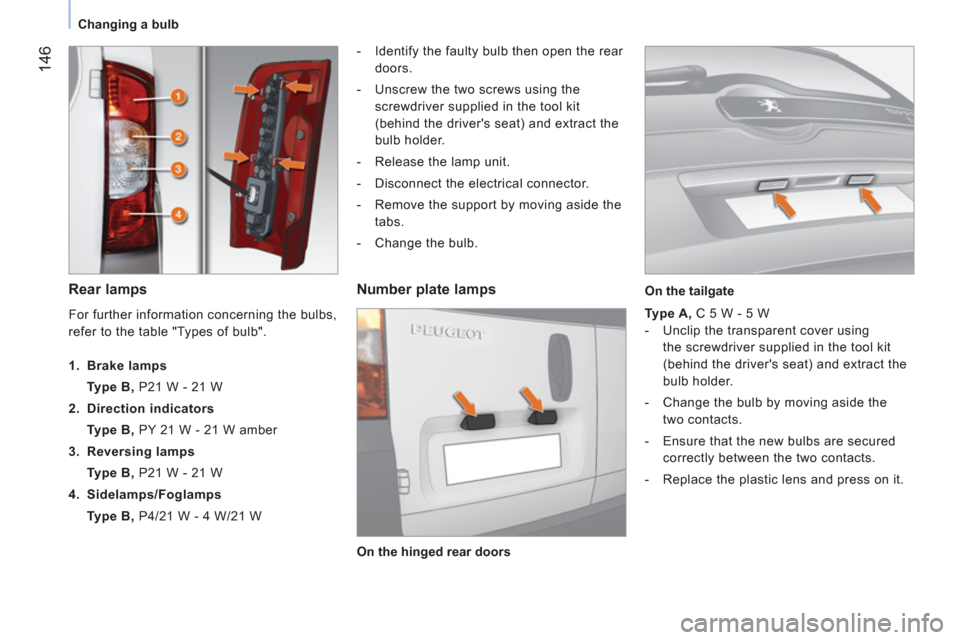
Rear lamps
- Identify the faulty bulb then open the rear
doors.
- Unscrew the two screws using the
screwdriver supplied in the tool kit
(behind the driver's seat) and extract the
bulb holder.
- Release the lamp unit.
- Disconnect the electrical connector.
- Remove the support by moving aside the
tabs.
- Change the bulb.
Number plate lamps
Type A, C 5 W - 5 W
- Unclip the transparent cover using
the screwdriver supplied in the tool kit
(behind the driver's seat) and extract the
bulb holder.
- Change the bulb by moving aside the
two contacts.
- Ensure that the new bulbs are secured
correctly between the two contacts.
- Replace the plastic lens and press on it.
For further information concerning the bulbs,
refer to the table "Types of bulb".
1. Brake lamps
Type B, P21 W - 21 W
2. Direction indicators
Type B, PY 21 W - 21 W amber
3. Reversing lamps
Type B, P21 W - 21 W
4. Sidelamps/Foglamps
Type B, P4/21 W - 4 W/21 W
On the hinged rear doors
On the tailgate
Page 149 of 180
14
7
7
QUICK HEL
P
Changing a bulb
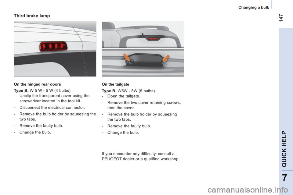
Third brake lamp
On the hinged rear doors
Type B,
W 5 W - 5 W (4 bulbs)
- Unclip the transparent cover using the
screwdriver located in the tool kit.
- Disconnect the electrical connector.
- Remove the bulb holder by squeezing the
two tabs.
- Remove the faulty bulb.
- Change the bulb.
On the tailgate
Type B,
W5W - 5W (5 bulbs)
- Open the tailgate.
- Remove the two cover retaining screws,
then the cover.
- Remove the bulb holder by squeezing
the two tabs.
- Remove the faulty bulb.
- Change the bulb.
If you encounter any difficulty, consult a
PEUGEOT dealer or a qualified workshop.
Page 152 of 180
150
Changing a fuse
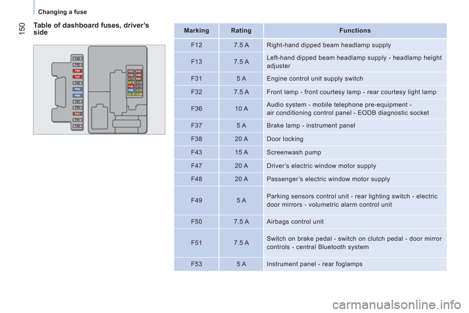
Table of dashboard fuses, driver’s
side
Mark
ing
Rating
Functions
F12
7.5 A Right-hand dipped beam headlamp supply
F13
7.5 A Left-hand dipped beam headlamp supply - headlamp height
adjuster
F31
5 A Engine control unit supply switch
F32
7.5 A Front lamp - front courtesy lamp - rear courtesy light lamp
F36
10 A Audio system - mobile telephone pre-equipment -
air conditioning control panel - EODB diagnostic socket
F37
5 A Brake lamp - instrument panel
F38
20 A Door locking
F43
15 A Screenwash pump
F47
20 A Driver’s electric window motor supply
F48
20 A Passenger’s electric window motor supply
F49
5 A Parking sensors control unit - rear lighting switch - electric
door mirrors - volumetric alarm control unit
F50
7.5 A Airbags control unit
F51
7.5 A Switch on brake pedal - switch on clutch pedal - door mirror
controls - central Bluetooth system
F53
5 A Instrument panel - rear foglamps
Page 156 of 180
154
Having your vehicle towed
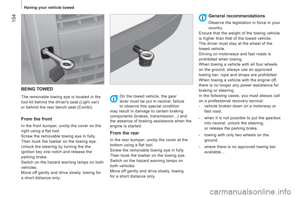
BEING TOWED
The removable towing eye is located in the
tool kit behind the driver's seat (Light van)
or behind the rear bench seat (Combi).
From the front
In the front bumper, unclip the cover on the
right using a flat tool.
Screw the removable towing eye in fully.
Then hook the towbar on the towing eye.
Unlock the steering by turning the the
ignition key one notch and release the
parking brake.
Switch on the hazard warning lamps on both
vehicles.
Move off gently and drive slowly, towing for
a short distance only.
On the towed vehicle, the gear
lever must be put in neutral; failure
to observe this special condition
may result in damage to certain braking
components (brakes, transmission...) and
the absence of braking assistance when the
engine is started.
From the rear
In the rear bumper, unclip the cover at the
bottom using a flat tool.
Screw the removable towing eye in fully.
Then hook the towbar on the towing eye.
Switch on the hazard warning lamps on
both vehicles.
Move off gently and drive slowly, towing
for a short distance only.
General recommendations
Observe the legislation in force in your
country.
Ensure that the weight of the towing vehicle
is higher than that of the towed vehicle.
The driver must stay at the wheel of the
towed vehicle.
Driving on motorways and fast roads is
prohibited when towing.
When towing a vehicle with all four wheels
on the ground, always use an approved
towing bar; rope and straps are prohibited.
When towing a vehicle with the engine off,
there is no longer any power assistance for
braking or steering.
In the following cases, you must always call
on a professional recovery service:
- vehicle broken down on a motorway or
fast road,
- when it is not possible to put the gearbox
into neutral, unlock the steering,
or release the parking brake,
- towing with only two wheels on the
ground,
- where there is no approved towing bar
available...
Page 162 of 180
160
Under the bonnet
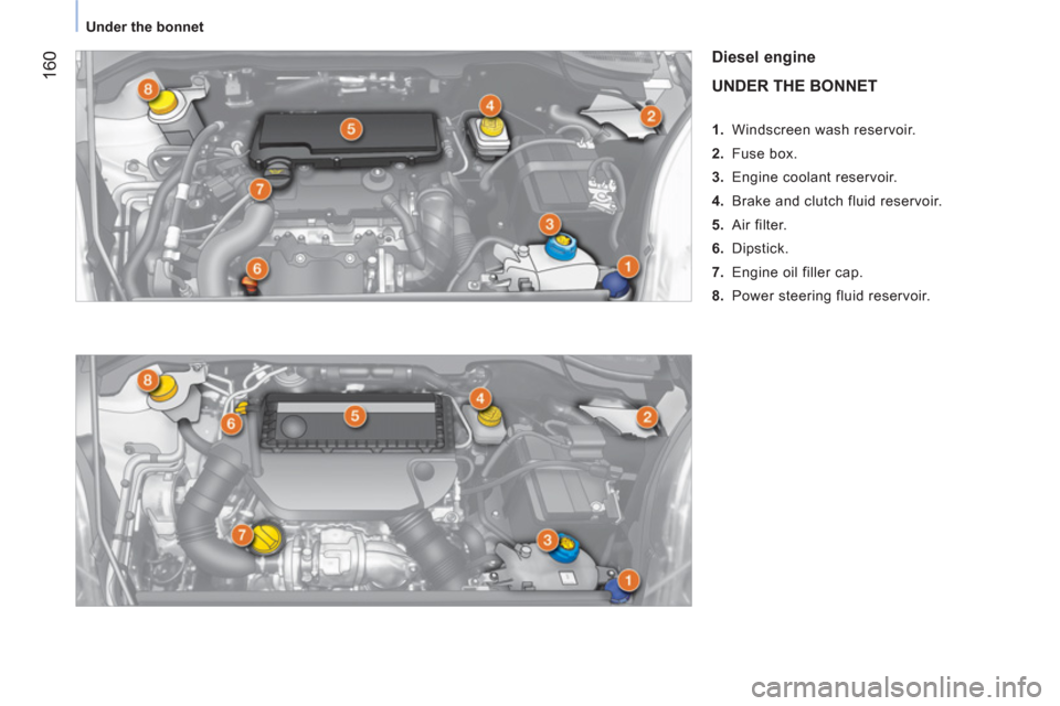
Diesel engine
UNDER THE BONNET
1. Windscreen wash reservoir.
2. Fuse box.
3. Engine coolant reservoir.
4. Brake and clutch fluid reservoir.
5. Air filter.
6. Dipstick.
7. Engine oil filler cap.
8. Power steering fluid reservoir.
Page 163 of 180
161
7
QUICK HEL
P
Under the bonnet
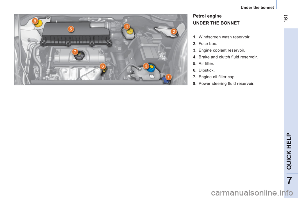
Petrol engine
UNDER THE BONNET
1. Windscreen wash reservoir.
2. Fuse box.
3. Engine coolant reservoir.
4. Brake and clutch fluid reservoir.
5. Air filter.
6. Dipstick.
7. Engine oil filler cap.
8. Power steering fluid reservoir.