brake PEUGEOT BOXER 2021 Owner's Guide
[x] Cancel search | Manufacturer: PEUGEOT, Model Year: 2021, Model line: BOXER, Model: PEUGEOT BOXER 2021Pages: 212, PDF Size: 6.37 MB
Page 120 of 212
11 8
In the event of a breakdown
Temporary puncture repair kit
This temporary puncture repair kit is stored in a
bag, placed in one of the front doors.
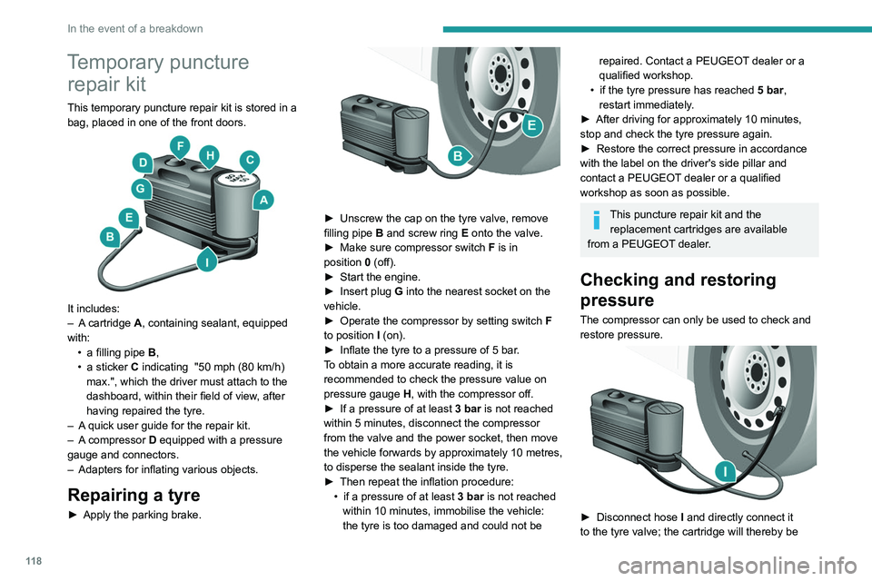
It includes:
–
A cartridge A, containing sealant, equipped
with: •
a filling pipe B
,
•
a sticker
C indicating "50 mph (80 km/h)
max.", which the driver must attach to the
dashboard, within their field of view, after
having repaired the tyre.
–
A
quick user guide for the repair kit.
–
A
compressor D equipped with a pressure
gauge and connectors.
–
Adapters for inflating various objects.
Repairing a tyre
► Apply the parking brake.
► Unscrew the cap on the tyre valve, remove
filling pipe B and screw ring E onto the valve.
►
Make sure compressor switch F
is in
position
0
(off).
►
Start the engine.
►
Insert plug
G into the nearest socket on the
vehicle.
►
Operate the compressor by setting switch F
to position I (on).
►
Inflate the tyre to a pressure of 5 bar
.
To obtain a more accurate reading, it is
recommended to check the pressure value on
pressure gauge H, with the compressor off.
►
If a pressure
of at least 3 bar is not reached
within 5 minutes, disconnect the compressor
from the valve and the power socket, then move
the vehicle forwards by approximately 10 metres,
to disperse the sealant inside the tyre.
►
Then repeat the inflation procedure:
•
if a pressure of at least
3 bar is not reached
within 10 minutes, immobilise the vehicle:
the tyre is too damaged and could not be
repaired. Contact a PEUGEOT dealer or a
qualified workshop.
•
if the tyre pressure has reached 5 bar
,
restart immediately.
►
After driving for approximately 10 minutes,
stop and check the tyre pressure again.
►
Restore the correct pressure in accordance
with the label on the driver's side pillar and
contact a PEUGEOT
dealer or a qualified
workshop as soon as possible.
This puncture repair kit and the replacement cartridges are available
from a PEUGEOT dealer.
Checking and restoring
pressure
The compressor can only be used to check and
restore pressure.
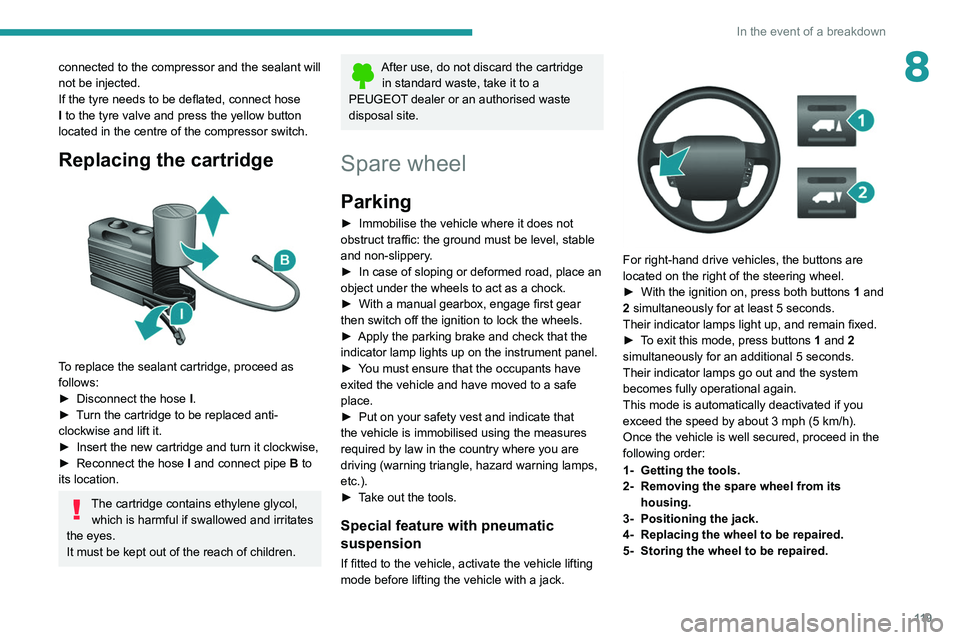
► Disconnect hose I and directly connect it
to the tyre valve; the cartridge will thereby be
Page 121 of 212
11 9
In the event of a breakdown
8connected to the compressor and the sealant will
not be injected.
If the tyre needs to be deflated, connect hose
I to the tyre valve and press the yellow button
located in the centre of the compressor switch.
Replacing the cartridge
To replace the sealant cartridge, proceed as
follows:
►
Disconnect the hose
I
.
►
T
urn the cartridge to be replaced anti-
clockwise and lift it.
►
Insert the new cartridge and turn it clockwise,
►
Reconnect the hose
I
and connect pipe B to
its location.
The cartridge contains ethylene glycol, which is harmful if swallowed and irritates
the eyes.
It must be kept out of the reach of children.
After use, do not discard the cartridge in standard waste, take it to a
PEUGEOT dealer or an authorised waste
disposal site.
Spare wheel
Parking
► Immobilise the vehicle where it does not
obstruct traffic: the ground must be level, stable
and non-slippery
.
►
In case of sloping or deformed road, place an
object under the wheels to act as a chock.
►
With a manual gearbox, engage first gear
then switch off the ignition to lock the wheels.
►
Apply the parking brake and check that the
indicator lamp lights up on the instrument panel.
►
Y
ou must ensure that the occupants have
exited the vehicle and have moved to a safe
place.
►
Put on your safety vest and indicate that
the vehicle is immobilised using the measures
required by law in the country where you are
driving (warning triangle, hazard warning lamps,
etc.).
►
T
ake out the tools.
Special feature with pneumatic
suspension
If fitted to the vehicle, activate the vehicle lifting
mode before lifting the vehicle with a jack.
For right-hand drive vehicles, the buttons are
located on the right of the steering wheel.
►
With the ignition on, press both buttons 1
and
2 simultaneously for at least 5 seconds.
Their indicator lamps light up, and remain fixed.
►
T
o exit this mode, press buttons 1 and 2
simultaneously for an additional 5 seconds.
Their indicator lamps go out and the system
becomes fully operational again.
This mode is automatically deactivated if you
exceed the speed by about 3 mph (5 km/h).
Once the vehicle is well secured, proceed in the
following order:
1- Getting the tools.
2- Removing the spare wheel from its housing.
3- Positioning the jack.
4- Replacing the wheel to be repaired.
5- Storing the wheel to be repaired.
Page 130 of 212
128
In the event of a breakdown
Front/Rear
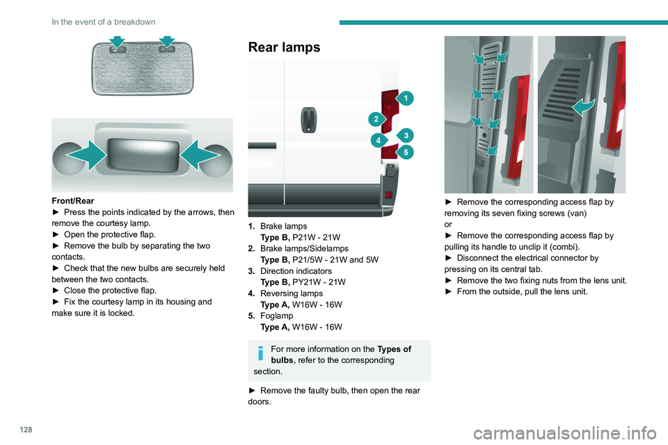
► Press the points indicated by the arrows, then
remove the courtesy lamp.
►
Open the protective flap.
►
Remove the bulb by separating the two
contacts.
►
Check that the new bulbs are securely held
between the two contacts.
►
Close the protective flap.
►
Fix the courtesy lamp in its housing and
make sure it is locked.
Rear lamps
1. Brake lamps
Type B, P21W - 21W
2. Brake lamps/Sidelamps
Type B, P21/5W - 21W and 5W
3. Direction indicators
Type B, PY21W - 21W
4. Reversing lamps
Type A, W16W - 16W
5. Foglamp
Type A, W16W - 16W
For more information on the Types of
bulbs, refer to the corresponding
section.
►
Remove the faulty bulb, then open the rear
doors.
► Remove the corresponding access flap by
removing its seven fixing screws (van)
or
►
Remove the corresponding access flap by
pulling its handle to unclip it (combi).
►
Disconnect the electrical connector by
pressing on its central tab.
►
Remove the two fixing nuts from the lens unit.
►
From the outside, pull the lens unit.
Page 131 of 212
129
In the event of a breakdown
8
► Remove the six fixing screws from the bulb
holder .
►
Open the three retaining tabs and pull the
bulb holder out of its housing.
►
Replace the bulb.
►
Carry out the operations in reverse order to
reposition each bulb.
Number plate lamps
Type C, C5W - 5W
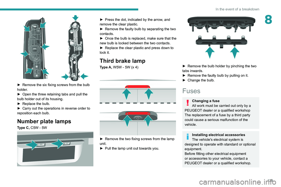
► Press the dot, indicated by the arrow , and
remove the clear plastic.
►
Remove the faulty bulb by separating the two
contacts.
►
Once the bulb is replaced, make sure that the
new bulb is locked between the two contacts.
►
Replace the clear plastic and press down to
lock it.
Third brake lamp
Type A, W5W - 5W (x 4)
► Remove the two fixing screws from the lamp
unit.
►
Pull the lamp unit out towards you.
► Remove the bulb holder by pinching the two
tabs inwards.
►
Remove the faulty bulb by pulling on it.
►
Change the bulb.
Fuses
Changing a fuse
All work must be carried out only by a
PEUGEOT dealer or a qualified workshop
The replacement of a fuse by a third party
could cause a serious malfunction of the
vehicle.
Installing electrical accessories
The vehicle's electrical system is
designed to operate with standard or optional
equipment.
Before fitting other electrical equipment
or accessories to your vehicle, contact a
PEUGEOT dealer or a qualified workshop.
Page 135 of 212
133
In the event of a breakdown
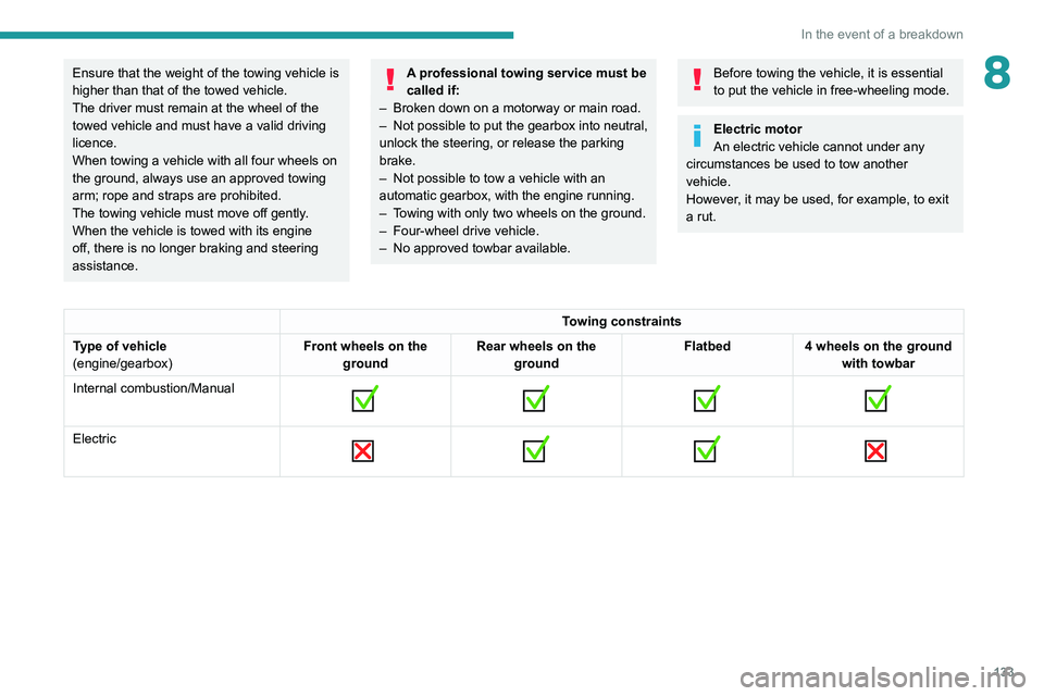
8Ensure that the weight of the towing vehicle is
higher than that of the towed vehicle.
The driver must remain at the wheel of the
towed vehicle and must have a valid driving
licence.
When towing a vehicle with all four wheels on
the ground, always use an approved towing
arm; rope and straps are prohibited.
The towing vehicle must move off gently.
When the vehicle is towed with its engine
off, there is no longer braking and steering
assistance.A professional towing service must be
called if:
–
Broken down on a motorway or main road.
–
Not possible to put
the gearbox into neutral,
unlock the steering, or release the parking
brake.
–
Not possible to tow a vehicle with an
automatic gearbox, with the engine running.
–
T
owing with only two wheels on the ground.
–
Four-wheel drive vehicle.
–
No approved towbar available.
Before towing the vehicle, it is essential
to put the vehicle in free-wheeling mode.
Electric motor
An electric vehicle cannot under any
circumstances be used to tow another
vehicle.
However, it may be used, for example, to exit
a rut.
Towing constraints
Type of vehicle
(engine/gearbox) Front wheels on the
ground Rear wheels on the
ground Flatbed
4 wheels on the ground
with towbar
Internal combustion/Manual
Electric
Page 139 of 212
137
Technical data
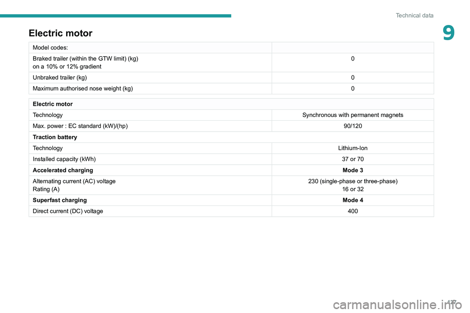
9Electric motor
Model codes:
Braked trailer (within the GTW limit) (kg)
on a 10% or 12% gradient0
Unbraked trailer (kg) 0
Maximum authorised nose weight (kg) 0
Electric motor
TechnologySynchronous with permanent magnets
Max. power : EC standard (kW)/(hp) 90/120
Traction battery
Technology Lithium-Ion
Installed capacity (kWh) 37 or 70
Accelerated charging Mode 3
Alternating current (AC) voltage
Rating (A) 230 (single-phase or three-phase)
16 or 32
Superfast charging Mode 4
Direct current (DC) voltage 400
Page 140 of 212
138
Technical data
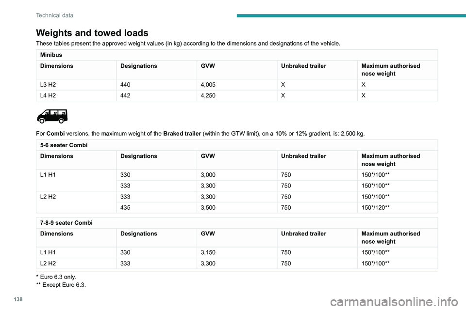
Weights and towed loads
These tables present the approved weight values (in kg) according to the dimensions and designations of the vehicle.
Minibus
DimensionsDesignationsGVWUnbraked trailerMaximum authorised
nose weight
L3 H2 4404,005XX
L4 H2 4424,250XX
For Combi versions, the maximum weight of the Braked trailer (within the GTW limit), on a 10% or 12% gradient, is: 2,500 kg.
5-6 seater Combi
DimensionsDesignationsGVWUnbraked trailerMaximum authorised
nose weight
L1 H1 3303,000750150*/100**
333 3,300750150*/100**
L2 H2 3333,300750150*/100**
435 3,500750150*/120**
7-8-9 seater Combi
DimensionsDesignationsGVWUnbraked trailerMaximum authorised
nose weight
L1 H1 3303,150750150*/100**
L2 H2 3333,300750150*/100**
* Euro 6.3 only.
** Except Euro 6.3.
Page 141 of 212
139
Technical data
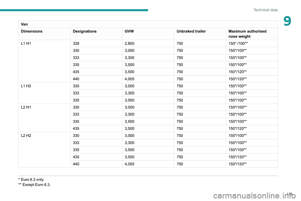
9Va n
DimensionsDesignationsGVWUnbraked trailerMaximum authorised
nose weight
L1 H1 3282,800750150*
/100**
330 3,000750150*/100**
333 3,300750150*/100**
335 3,500750150*/100**
435 3,500750150*/120**
440 4,005750150*/120**
L1 H2 3303,000750150*/100**
333 3,300750150*/100**
335 3,500750150*/100**
L2 H1 3303,000750150*/100**
333 3,300750150*/100**
335 3,500750150*/100**
435 3,500750150*/120**
L2 H2 3303,000750150*/100**
333 3,300750150*/100**
335 3,500750150*/100**
435 3,500750150*/120**
440 4,005750150*/120**
* Euro 6.3 only.
** Except Euro 6.3.
Page 142 of 212
140
Technical data
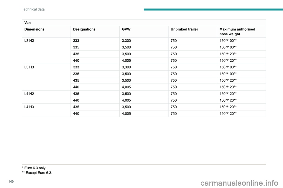
Va n
DimensionsDesignationsGVWUnbraked trailerMaximum authorised
nose weight
L3 H2 3333,300750150*/100**
335 3,500750150*/100**
435 3,500750150*/120**
440 4,005750150*/120**
L3 H3 3333,300750150*/100**
335 3,500750150*/100**
435 3,500750150*/120**
440 4,005750150*/120**
L4 H2 4353,500750150*/120**
440 4,005750150*/120**
L4 H3 4353,500750150*/120**
440 4,005750150*/120**
* Euro 6.3 only.
** Except Euro 6.3.
Page 148 of 212
146
Technical data
Glossary of labels
This section contains all of the text written on the
labels present in the vehicle.
For the Identification markings, refer to
the corresponding section.
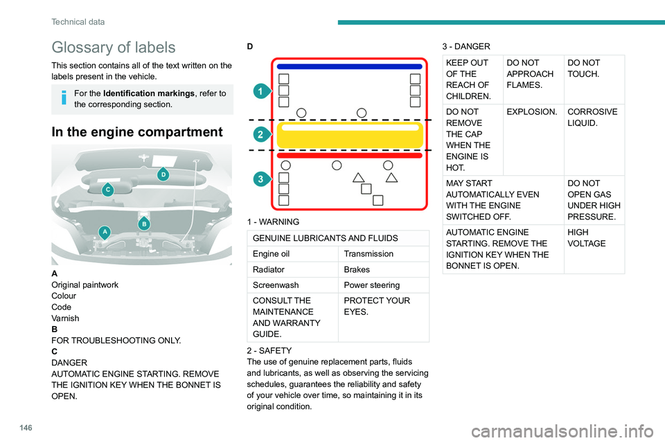
In the engine compartment
A
Original paintwork
Colour
Code
Varnish
B
FOR TROUBLESHOOTING ONLY.
C
DANGER
AUTOMATIC ENGINE STARTING. REMOVE
THE IGNITION KEY WHEN THE BONNET IS
OPEN. D
1 - WARNING
GENUINE LUBRICANTS AND FLUIDS
Engine oil
Transmission
Radiator Brakes
Screenwash Power steering
CONSULT THE
MAINTENANCE
AND WARRANTY
GUIDE. PROTECT YOUR
EYES.
2 - SAFETY
The use of genuine replacement parts, fluids
and lubricants, as well as observing the servicing
schedules, guarantees the reliability and safety
of your vehicle over time, so maintaining it in its
original condition. 3 - DANGER
KEEP OUT
OF THE
REACH OF
CHILDREN.
DO NOT
APPROACH
FLAMES.
DO NOT
TOUCH.
DO NOT
REMOVE
THE CAP
WHEN THE
ENGINE IS
HOT. EXPLOSION. CORROSIVE
LIQUID.
MAY START
AUTOMATICALLY EVEN
WITH THE ENGINE
SWITCHED OFF. DO NOT
OPEN GAS
UNDER HIGH
PRESSURE.
AUTOMATIC ENGINE
STARTING. REMOVE THE
IGNITION KEY WHEN THE
BONNET IS OPEN. HIGH
VOLTAGE