Peugeot Partner Tepee 2016 Owner's Manual
Manufacturer: PEUGEOT, Model Year: 2016, Model line: Partner Tepee, Model: Peugeot Partner Tepee 2016Pages: 296, PDF Size: 10.76 MB
Page 171 of 296
169
BAtteRY
Before disconnecting the battery, you
must wait for 2 minutes after switching
off the ignition.
Never disconnect a terminal when the
engine is running.
Never charge a battery without first
disconnecting the terminals.
After every reconnection of the battery,
switch on the ignition and wait 1 minute
before starting to allow the electronic
systems to be initialised. If problems
remain after doing this, please contact
a PEUGEOT dealer or a qualified
workshop.
After changing bulbs, wait
approximately 3 minutes before
reconnecting the battery.
It is advisable to disconnect the
battery if the vehicle is not to be
used for a period of more than
one
month.
to charge the battery using
a battery charger
- Disconnect the battery .
-
Follow the instructions for use
given by the battery charger
manufacturer
.
-
Reconnect starting with the
negative (-) terminal.
-
Check that the terminals and
connectors are clean. If they are
covered with sulphate (white or
greenish deposit), disconnect them
and clean them.
to start the vehicle from
another battery
- Connect the red cable to the
positive (+) terminals of the
two
batteries.
-
Connect one end of the green
or black cable to the negative (-)
terminal of the slave battery
.
-
Connect the other end of the green
or black cable to an earth point on
the broken down vehicle as far as
possible from the battery
.
-
o perate the starter, let the engine run.
-
W
ait for the engine to return to idle,
then disconnect the cables.
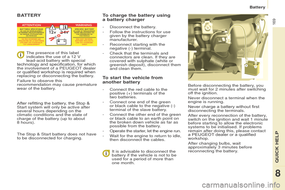
The presence of this label
indicates the use of a 12 V
lead-acid battery with special
technology and specification, for which
the involvement of a P
eugeo
T dealer
or qualified workshop is required when
replacing or disconnecting the battery.
Failure to observe this
recommendation may cause premature
wear of the battery.
After refitting the battery, the Stop
&
Start system will only be active after
several hours depending on the
climatic conditions and the state of
charge of the battery (up to about
8 hours).
The Stop & Start battery does not have
to be disconnected for charging.
Battery
8
QuICK HeLP
Page 172 of 296
170
eCoNoMY M o D e
After the engine has stopped, with
the key in the ignition position, certain
functions (windscreen wiper, electric
windows, courtesy lamps, audio
equipment, etc.) can only be used for a
cumulative duration of thirty minutes, to
prevent discharging of the battery.
o
nce the thirty minutes have elapsed,
the active functions are put on standby
and the battery warning lamp flashes
accompanied by a message in the
screen.
To resume the use of these functions
immediately, start the engine and let it
run for a few minutes.
The time available will then be double
the time for which the engine was left
running. However, this time will always
be between five and thirty minutes.
A flat battery will prevent the
engine from starting.
Battery
Page 173 of 296
171
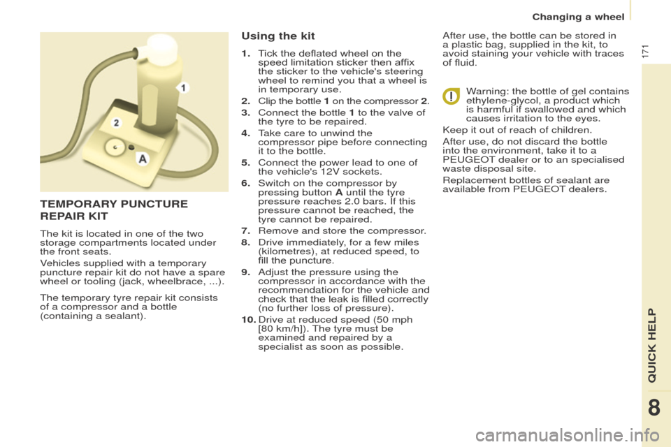
The temporary tyre repair kit consists
of a compressor and a bottle
(containing a sealant).
using the kit
1. Tick the deflated wheel on the speed limitation sticker then affix
the sticker to the vehicle's steering
wheel to remind you that a wheel is
in temporary use.
2.
Clip the bottle
1 on the compressor
2.
3.
Connect the bottle
1 to the valve of
the tyre to be repaired.
4.
T
ake care to unwind the
compressor pipe before connecting
it to the bottle.
5.
Connect the power lead to one of
the vehicle's 12V sockets.
6.
Switch on the compressor by
pressing button
A until the tyre
pressure reaches 2.0 bars. If this
pressure cannot be reached, the
tyre cannot be repaired.
7.
Remove and store the compressor
.
8.
Drive immediately
, for a few miles
(kilometres), at reduced speed, to
fill the puncture.
9.
Adjust the pressure using the
compressor in accordance with the
recommendation for the vehicle and
check that the leak is filled correctly
(no further loss of pressure).
10.
Drive at reduced speed (50
mph
[80 km/h]). The tyre must be
examined and repaired by a
specialist as soon as possible. After use, the bottle can be stored in
a plastic bag, supplied in the kit, to
avoid staining your vehicle with traces
of fluid.
Warning: the bottle of gel contains
ethylene-glycol, a product which
is harmful if swallowed and which
causes irritation to the eyes.
Keep it out of reach of children.
After use, do not discard the bottle
into the environment, take it to a
P
eugeo T dealer or to an specialised
waste disposal site.
Replacement bottles of sealant are
available from P
eugeo T dealers.
teMPoRARY P u NC tu R e
R
e PAIR KI t
The kit is located in one of the two
storage compartments located under
the front seats.
Vehicles supplied with a temporary
puncture repair kit do not have a spare
wheel or tooling (jack, wheelbrace, ...).
8
QuICK HeLP
Changing a wheel
Page 174 of 296
172
1. Parking the vehicle
- The occupants must get out of the
vehicle and wait in a safe location.
-
If possible, park the vehicle on level,
stable and non-slippery ground.
-
Apply the parking brake, switch
of
f the ignition and engage first or
reverse gear. -
Place a chock under the wheel
diagonally opposite the one to be
changed.
CHANgINg A WH
ee L
2.
t
ools
The tools are stowed in a storage area
closed by a flap under a front seat.
-
If necessary
, move the seat forward
to access the storage compartment
from the rear.
-
Remove the flap then take out the
jack and the tool carrier
.
-
Remove the tools needed from the
carrier
.
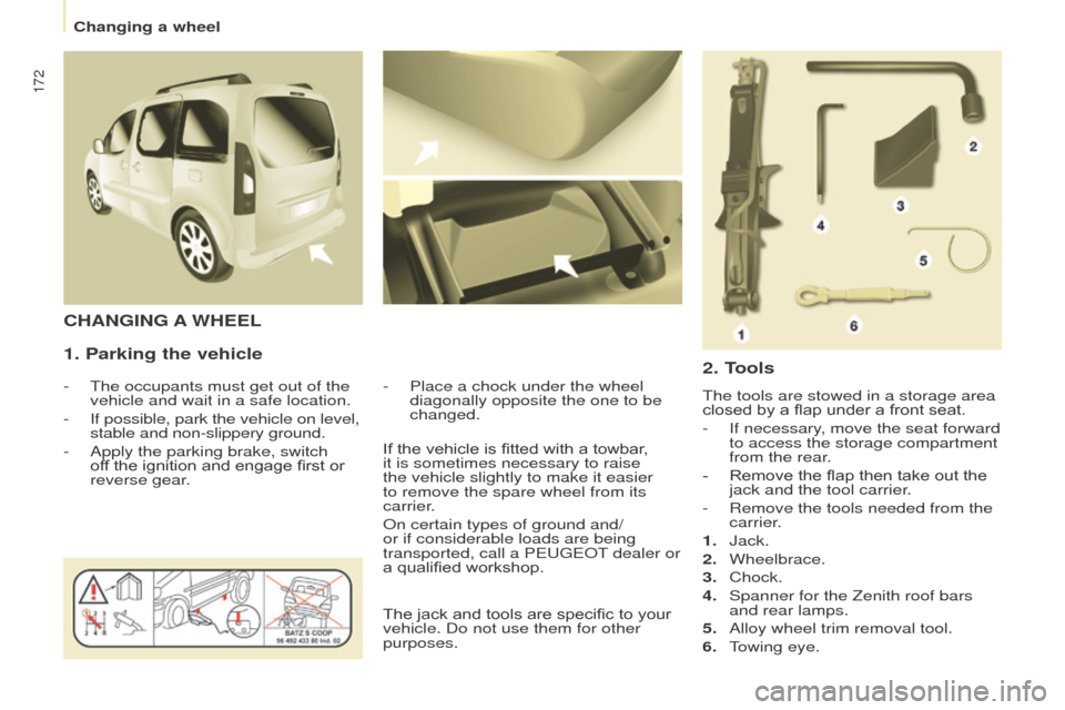
1.
Jack.
2.
Wheelbrace.
3.
Chock.
4.
Spanner for the Zenith roof bars
and rear lamps.
5.
Alloy wheel trim removal tool.
6.
T
owing eye.
If the vehicle is fitted with a towbar,
it is sometimes necessary to raise
the vehicle slightly to make it easier
to remove the spare wheel from its
carrier.
o
n certain types of ground and/
or if considerable loads are being
transported, call a P
eugeo
T dealer or
a qualified workshop.
The jack and tools are specific to your
vehicle. Do not use them for other
purposes.
Changing a wheel
Page 175 of 296
173
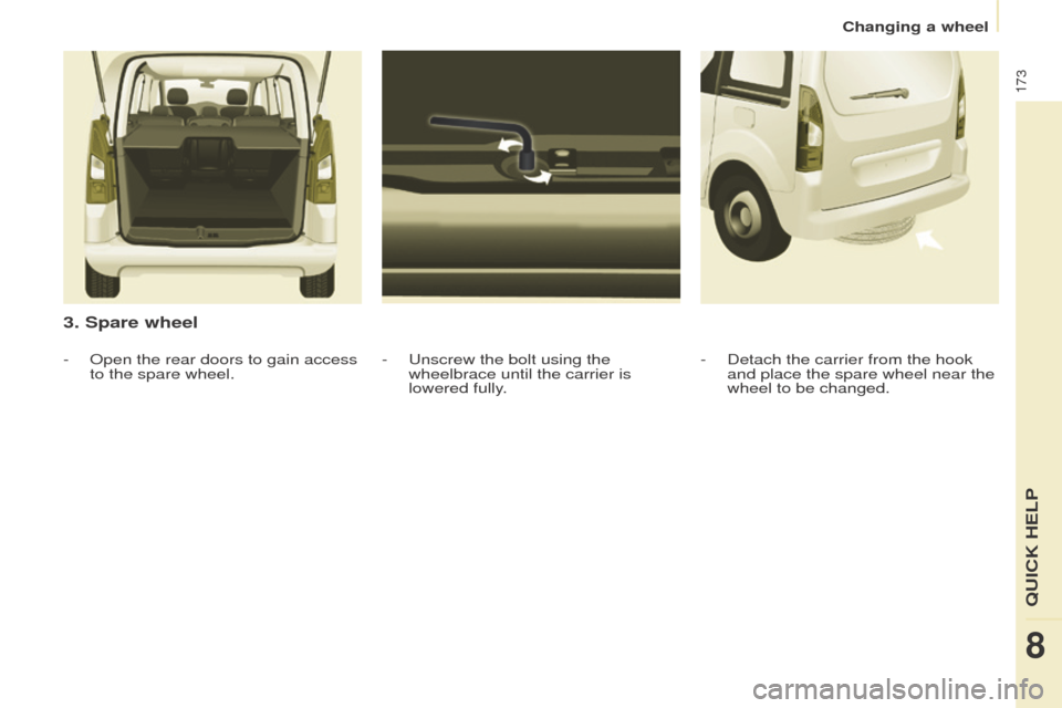
3. Spare wheel
- unscrew the bolt using the
wheelbrace until the carrier is
lowered fully
.
-
o
pen the rear doors to gain access
to the spare wheel. -
Detach the carrier from the hook
and place the spare wheel near the
wheel to be changed.
8
QuICK HeLP
Changing a wheel
Page 176 of 296
174
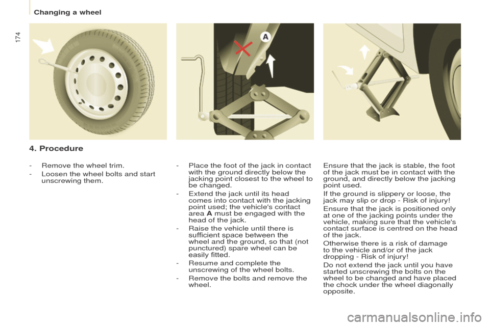
4. Procedure
- Place the foot of the jack in contact
with the ground directly below the
jacking point closest to the wheel to
be changed.
-
e xtend the jack until its head
comes into contact with the jacking
point used; the vehicle's contact
area A must be engaged with the
head of the jack.
-
Raise the vehicle until there is
sufficient space between the
wheel and the ground, so that (not
punctured) spare wheel can be
easily fitted.
-
Resume and complete the
unscrewing of the wheel bolts.
-
Remove the bolts and remove the
wheel.
-
Remove the wheel trim.
-
Loosen the wheel bolts and start
unscrewing them.
e nsure that the jack is stable, the foot
of the jack must be in contact with the
ground, and directly below the jacking
point used.
If the ground is slippery or loose, the
jack may slip or drop - Risk of injury!
e
nsure that the jack is positioned only
at one of the jacking points under the
vehicle, making sure that the vehicle's
contact surface is centred on the head
of the jack.
o
therwise there is a risk of damage
to the vehicle and/or of the jack
dropping
- Risk of injury!
Do not extend the jack until you have
started unscrewing the bolts on the
wheel to be changed and have placed
the chock under the wheel diagonally
opposite.
Changing a wheel
Page 177 of 296
175
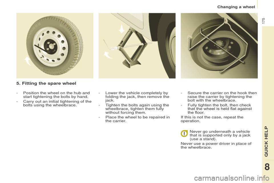
- Position the wheel on the hub and
start tightening the bolts by hand.
-
Carry out an initial tightening of the
bolts using the wheelbrace.
5. Fitting the spare wheel
- Lower the vehicle completely by
folding the jack, then remove the
jack.
-
T
ighten the bolts again using the
wheelbrace, tighten them fully
without forcing them.
-
Place the wheel to be repaired in
the carrier
. -
Secure the carrier on the hook then
raise the carrier by tightening the
bolt with the wheelbrace.
-
Fully tighten the bolt, then check
that the wheel is held flat against
the floor
.
If this is not the case, repeat the
operation.
Never go underneath a vehicle
that is supported only by a jack
(use a stand).
Never use a power driver in place of
the wheelbrace.
8
QuICK HeLP
Changing a wheel
Page 178 of 296
176
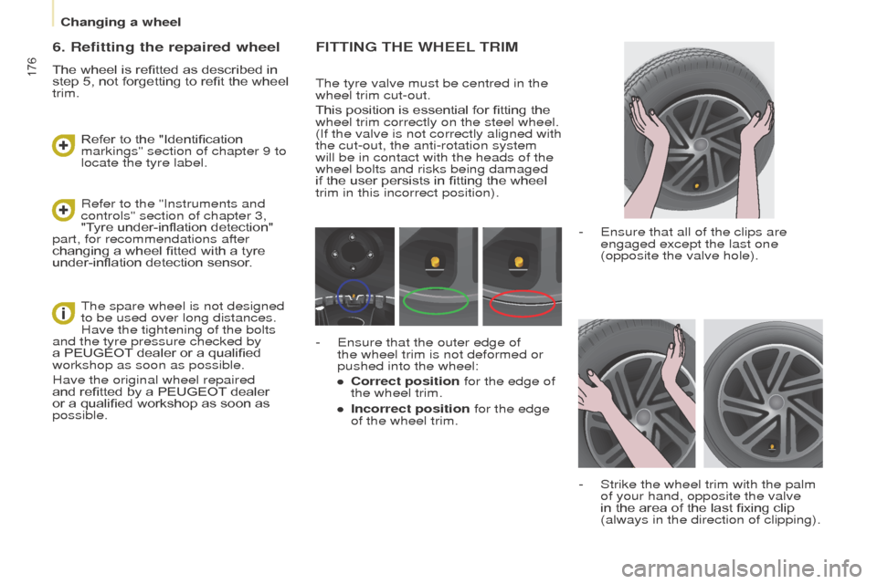
FIttINg tHe WHeeL tRIM
The tyre valve must be centred in the
wheel trim cut-out.
This position is essential for fitting the
wheel trim correctly on the steel wheel.
(If the valve is not correctly aligned with
the cut-out, the anti-rotation system
will be in contact with the heads of the
wheel bolts and risks being damaged
if the user persists in fitting the wheel
trim in this incorrect position).
-
e nsure that all of the clips are
engaged except the last one
(opposite the valve hole).
-
Strike the wheel trim with the palm
of your hand, opposite the valve
in the area of the last fixing clip
(always in the direction of clipping).
-
e nsure that the outer edge of
the wheel trim is not deformed or
pushed into the wheel:
●
Correct position
for the edge of
the wheel trim.
●
Incorrect position
for the edge
of the wheel trim.
6. Refitting the repaired wheel
The wheel is refitted as described in
step 5, not forgetting to refit the wheel
trim.
Refer to the "Instruments and
controls" section of chapter 3,
"Tyre under-inflation detection"
part, for recommendations after
changing a wheel fitted with a tyre
under-inflation detection sensor. Refer to the "Identification
markings" section of chapter 9 to
locate the tyre label.
The spare wheel is not designed
to be used over long distances.
Have the tightening of the bolts
and the tyre pressure checked by
a PEUGEOT dealer or a qualified
workshop as soon as possible.
Have the original wheel repaired
and refitted by a PEUGEOT dealer
or a qualified workshop as soon as
possible.
Changing a wheel
Page 179 of 296
177
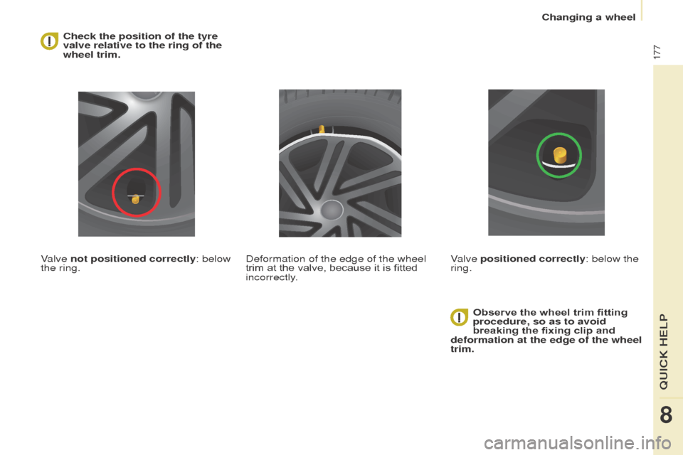
Check the position of the tyre
valve relative to the ring of the
wheel trim.
Valve not positioned correctly: below
the ring. Observe the wheel trim fitting
procedure, so as to avoid
breaking the fixing clip and
deformation at the edge of the wheel
trim.
Deformation of the edge of the wheel
trim at the valve, because it is fitted
incorrectly.
Valve positioned correctly: below the
ring.
8
QuICK HeLP
Changing a wheel
Page 180 of 296
178
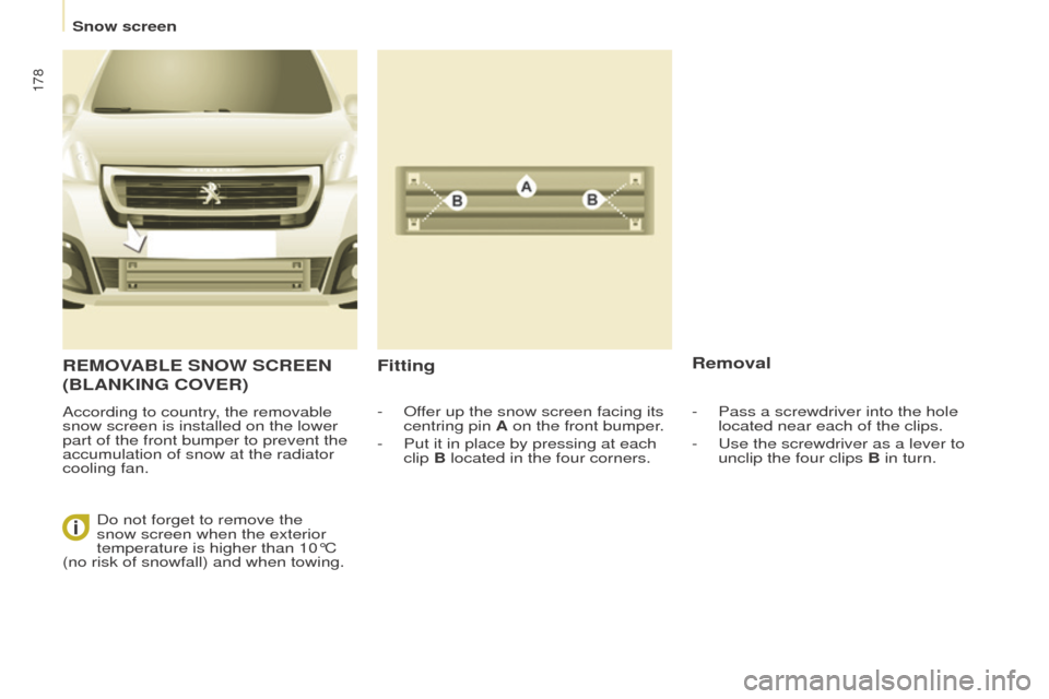
ReMoVABLe SNoW SCReeN
( BLANKIN g C o V e R )
According to country, the removable
snow screen is installed on the lower
part of the front bumper to prevent the
accumulation of snow at the radiator
cooling fan.
Fitting Removal
- offer up the snow screen facing its
centring pin A on the front bumper.
-
Put it in place by pressing at each
clip
B located in the four corners.
Do not forget to remove the
snow screen when the exterior
temperature is higher than 10°C
(no risk of snowfall) and when towing. -
Pass a screwdriver into the hole
located near each of the clips.
-
u se the screwdriver as a lever to
unclip the four clips B in turn.
Snow screen