turn signal PONTIAC FIERO 1988 Service Owners Manual
[x] Cancel search | Manufacturer: PONTIAC, Model Year: 1988, Model line: FIERO, Model: PONTIAC FIERO 1988Pages: 1825, PDF Size: 99.44 MB
Page 950 of 1825
DRlVEABlLlPV AND EMISSIONS 5.OL (VIN F) & 5.7L (VIN 8) 6E3-C"1-1
SECTION Cl2
COOLING FAN CONTROL
CONTENTS
GENERAL DESCRIPTION ................ C12-I DIAGNOSIS ......................... C1Z-1
OPERATION ..................... .. C12-1 ON-CARSERVICE ..................... C12-1
PARTS INFORMATION ................. C12-1
GENERAL DESCRIPIION DlAGNODlS
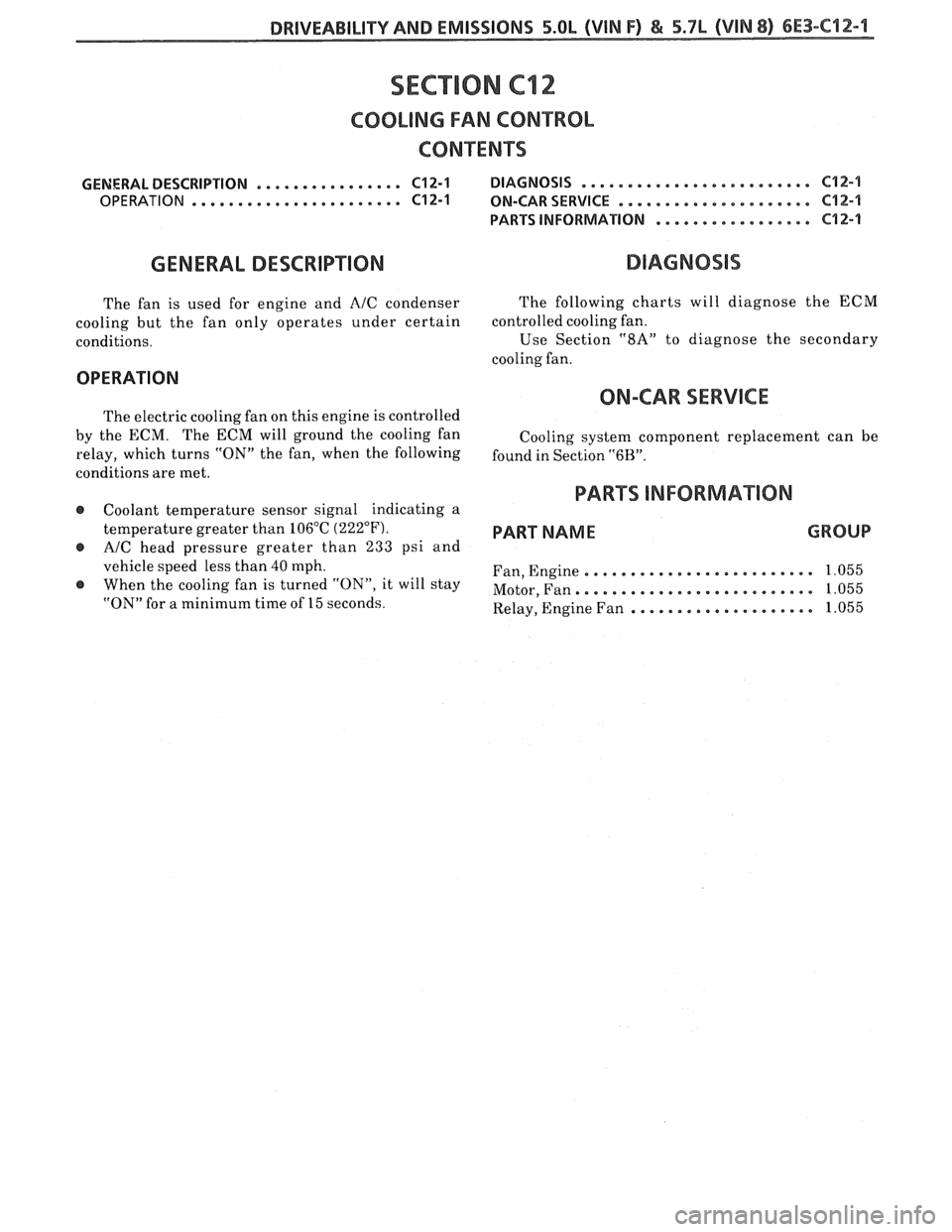
The fan is used for engine and AIC condenser
cooling but the fan only operates under certain
conditions. The
following charts will diagnose the ECM
controlled cooling fan.
Use
Sect.ion "8A" to diagnose the secondary
cooling fan.
OPERATION
ON-CAR SERVICE
The electric cooling fan on this engine is controlled
by the ECM. The ECM will ground the cooling fan
relay, which turns "ON" the fan, when the following
conditions are met.
@ Coolant temperature sensor signal indicating a
temperature greater than 106°C
(222°F).
@ AIC head pressure greater than 233 psi and
vehicle speed less than 40 mph.
When the cooling fan is turned "ON", it will stay
"ON" for a minimum time of 15 seconds. Cooling
system component replacement can be
found in Section
"6B".
PARTS INFORMATION
PART NAME GROUP
......................... Fan, Engine 1.055
......................... Motor, Fan. 1.055
.................... Relay, Engine Fan 1.055
Page 951 of 1825
6E3-C12-2 5.OL (VIN F) & 5.7b (VIN 8) DRIVEABILITY AND EMISSIONS
FAN CONTROL
RELAY CONN.
DK GRNNVHT 335
TEMPERATURE
SENSOR SIGNAL.
TURNS ON PRIMARY
FAN AT
223OF (1 06'C)
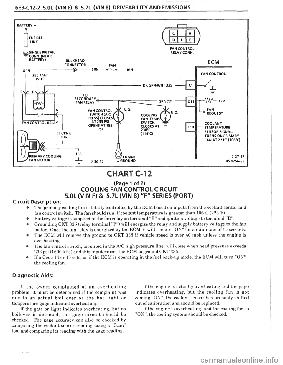
CHART C-12
(Page 1 of 2)
COOLING FAN CONTROL CIRCUIT
5.8L (VIN F) & 5.7L (VIN 8) "F" SSERlES (PORT)
Circuit Description:
The primary cooling fan is totally controlled by the ECM based on inputs from the coolant sensor and
fan control switch. The fan should run, if coolant temperature is greater than 106°C
(223°F).
@ Battery voltage is supplied to the fan relay on terminal "En and ignition voltage to terminal "D".
@ Grounding CKT 335 (relay terminal "F") will energize the relay and supply battery voltage to the fan
motor. Once the fan relay is energized by the
ECM, it will remain "ON" for a minimum of 15 seconds.
@ 'I'he ECM will remove the ground to CKT 335 if vehicle speed is over 40 rnph unless the engine is
overheating.
@ 'I'he fan control switch, mounted in Lhe AIC high pressure line, will close when head pressure exceeds
233 psi (1600 kPa) and this input causes the ECM to ground CKT 335.
@ If a Code 14 or 15 sets, or if the ECM is operating in the fuel back-up mode, the ECM will turn "ON"
the cooling fan.
Diagnostic Aids:
If the owner complained of an overheating If
the engine is actually overheating and the gage
problem, it must be determined if the complaint was indicates
overheating, but
t,he cooling fan is not
due to an actual boil over or the hot light or coming
"ON", the
coolant sensor has probably shifted
temperature gage indicated overheating. out
of calibration and should be replaced.
If the gate or light indicates overheating, but no If
the engine is overheating, and the cooling fan is
boilover is detected, the gage circuit should be "ON", the cooling system should be checked.
checked. The gage accuracy can also be checked by
comparing the coolant sensor reading using
a "Scan.'
tool and comparing its reading with the gage reading.
Page 953 of 1825
6E3-C12-4 5.8L (VIN F) & 5.7L (VIN 8) DRIVEABILITY AND EMISSIONS
FAN CONTROL
SINGLE PIGTAIL RELAY CONN.
DK GRNNVHT 335
OPENS AT
185 TEMPERATURE SENSOR SIGNAL.
TURNS ON PRIMARY
FAN AT 223°F
(106°C)
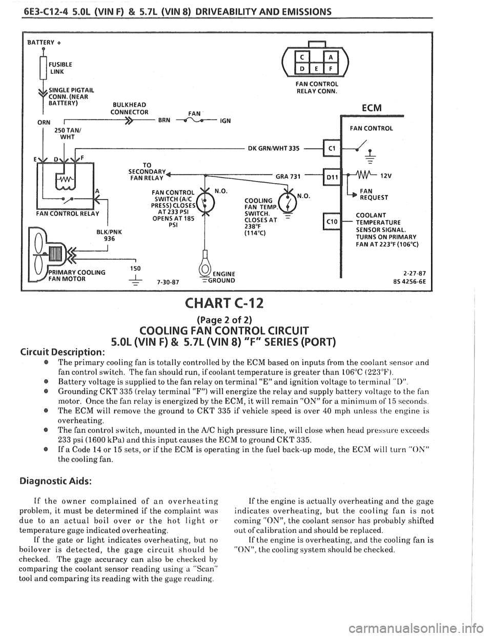
CHART C-12
(Page 2 of 2)
COOLING FAN CONTROL CIRCUIT
5.OL (VIN F) & 5.7L (VIN 8) ""FYSERlES (PORT)
Circuit Description:
@ The primary cooling fan is totally controlled by the ECM based on inputs from the coolant sensor and
fan control switch. The fan should run, if coolant temperature is greater than 106°C
(223°F).
@ Battery voltage is supplied to the fan relay on terminal "En and ignition voltage to terminal "I)"
@ Grounding CKT 335 (relay terminal "F") will energize the relay and supply battery voltage to the fan
motor. Once the fan relay is energized by the ECM, it will remain "ON" for a mini~nuln of 15 seconds
@ The ECM will remove the ground to CKT 335 if vehicle speed is over 40 mph unless the engine is
overheating.
@ The fan control switch, mounted in the A/C high pressure line, will close when head pressure exceeds
233 psi (1600 kPa) and this input causes the ECM to ground CKT 335.
@ If a Code 14 or 15 sets, or if the ECM is operating in the fuel back-up mode, the ECM will turn "OX"
the cooling fan.
Diagnostic Aids:
If the owner complained of an overheating If the engine is actually overheating and the gage
problem, it must be determined if the complaint was indicates overheating, but the cooling fan is not
due to an actual boil over or the hot light or coming
"ON", the coolant sensor has probably shifted
temperature gage indicated overheating. out
of calibration and should be replaced.
If the gate or light indicates overheating, but no If the engine is overheating, and the cooling fan is
boilover is detected, the gage circuit should be "ON". the cooling system should be checked.
checked. The gage accuracy can also be checked
by
comparing the coolant sensor reading using a "Scan"
tool and comparing its reading with the gage reading.
Page 970 of 1825
DRIVEABILITY AND EMISSIONS - FUEL INJECTION 6E-9
ParWNelatral Switch IAC (Idle Air Control)
The indication in this mode may vary with This system is used to control engine idle speed to
manufacturer so the type of reading for a particular the desired rpm, for different operating conditions. In
tool should be checked in the operator's manual. The this mode, the numbers will indicate the position to
important thing is that the the reading changes state which
the ECM has moved the valve pintle. The ECM
(switches) when the gear selector is moved from moves
the IAC in counts, or steps, and the number of
paridneutral to drive or reverse. these counts are displayed on a "Scan" tool.
"Trque Convertor Clutch (TCC)
In this position, the tool will indicate when the
TCC has been commanded by the ECM to turn "ONJ'.
This does not necessarily mean that the clutch was
engaged but only that the
ECM grounded the circuit
internally. The best way to determine if the clutch has
engaged is to monitor engine rpm when the TCC
comes "ON".
EGR (Duty Cycle)
The EGR system uses a valve to feed a small
amount of exhaust gas back into the intake manifold
to control formation of NO,. Like all ECM outputs, the
"Scan" tool only indicates that the ECM has
commanded the function, and does not indicate that
the function has really happened.
EGR Position
This indicates the position of the EGR pintle.
Integrator and Block Learn
Normal readings for these positions are around
128. If higher, it indicates that the ECM is adding fuel
to the base fuel calculation because the system is lean,
and if the numbers are below 128, the ECM is taking
out fuel from the base calculation because the system
is rich. The integrator gives short term corrective
action, while the block learn portion (which is a long
term correction) will only change if the integrator has
seen a condition which lasts for a calibrated period of
time.
Block Learn Multiplier (BLM) Cell - or -
Block Learn Memory (BLM)
There are up to sixteen different cells,
corresponding to ranges of rpm and engine load
(indicated by MAF or MAP signals), and other
conditions, such as
A/C or P/N switch "ON" or "OFF",
etc. The ECM learns how much adjustment is needed
in each cell, and retains it in memory, so that the
adjustment will immediately be made when the
engine operates in that cell (or
rpmlload range). This
parameter will display what cell the ECM is currently
using for the fuel calculation.
Desired RPM
This indicates the rpm to which the ECM is trying
to control the idle.
Shift Light
This displays "yes" when the ECM is commanding
the shift light to turn "ON".
PPSW (Pump Prime Switch)
This is the voltage on the fuel pump feed circuit.
The ECM will adjust fuel injector base pulse width
from this voltage value rather than from battery
voltage.
NC Request
The state of the A/C signal line to the ECM is
shown. It should read "yes" whenever the
IVC is
requested.
NC Clutch
"ON" is displayed when the ECM has commanded
the
A/C clutch "ON".
Knock Retard
This indicates the number of degrees the ECM is
retarding the electronic spark timing (EST).
Knock Signal
This displays a "yes" when knock is detected by
the ECM, and a "no" when knock is not detected.
Battery Voltage
This displays the battery voltage detected at the
ECM ignition input.
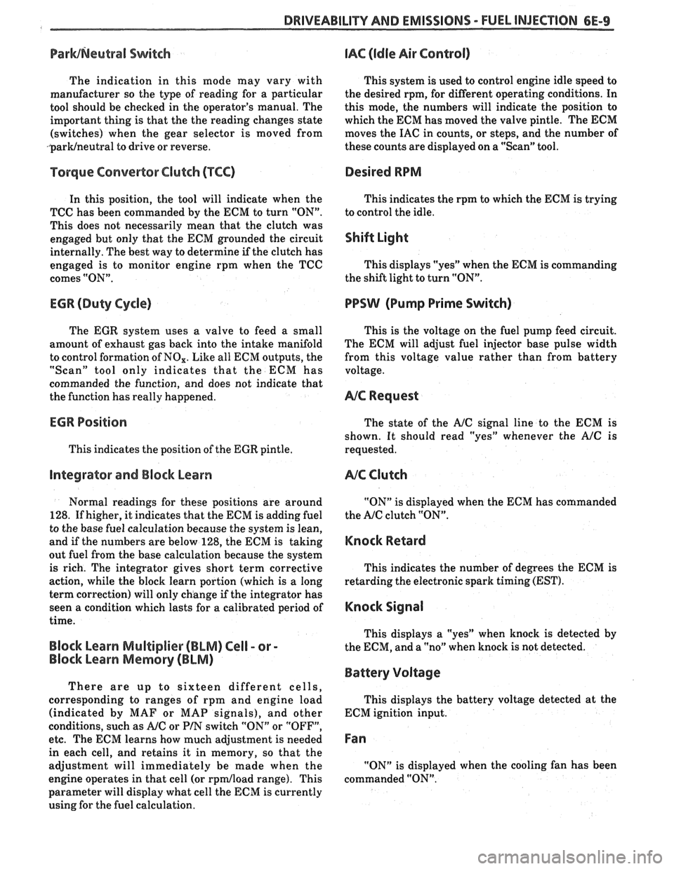
Fan
"ON" is displayed when the cooling fan has been
commanded "ON".
Page 972 of 1825
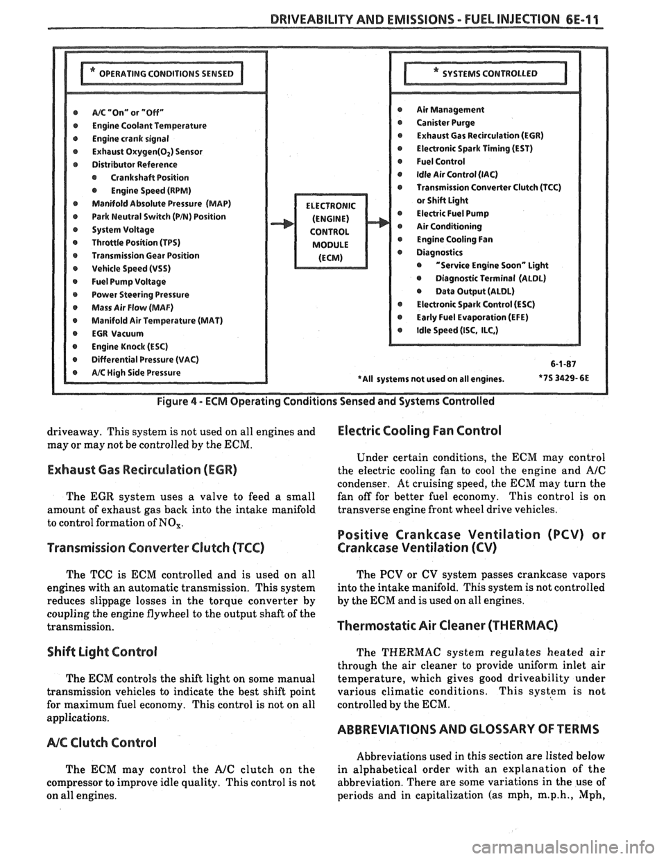
DRIVEABILITY AND EMISSIONS - FUEL INJEC"F0N 6E-11
@ A/% "On" or "Off" r Air Management
r Engine Coolant Temwrature r Canister Purge
@ Engine crank signal r Exhaust Gas Recirculation (EGR)
@ Exhaust Oxygen(02) Sensor @ Electronic Spark Timing (EST)
r Distributor Reference @ Fuel Control
@ Crankshaft Position @ Idle Air Control (lAC)
@ Engine Speed (RPM) Transmission Converter Clutch (TCC)
Manifold Absolute Pressure (MAP)
@ Park Neutral Switch (PB) Position @ Electric Fuel Pump
r System Voltage Air Conditioning
r Throttle Position (TPS) @ Engine Cooling Fan
r Transmission Gear Position
r Vehicle Speed (VSS) @ "Service Engine Soon" Light
@ Fuel Pump Voltage @ Diagnostic Terminal (ALDL)
r Power Steering Pressure @ Data Output (ALDL)
Mass Air Flow (MAF) @ Electronic Spark Control (ESC)
@ Manifold Air Temperature (MAT) @ Early Fuel Evaporation (EFE)
r EGR Vacuum @ Idle Speed (ISC, ILC,)
@ Engine Knock (ESC)
r Differential Pressure (VAC) 6-1-87
*7S
3429- 6E
Figure
4 - ECM Operating Conditions Sensed and Systems Controlled
driveaway. This system is not used on all engines and Electric Cooling Fan Control
may or may not be controlled by the ECM.
Under certain conditions, the
ECM may control
Exhaust Gas Recirculation (ECR) the electric cooling fan to cool the engine and A/C
condenser. At cruising speed, the ECM may turn the
The
EGR system uses a valve to feed a small fan
off for better fuel economy. This control is on
amount of exhaust gas back into the intake manifold transverse
engine front wheel drive vehicles.
to control formation of
NO,.
Positive Crankcase Ventilation (PCV) or
Transmission Converter
Clutch (TCC) Crankcase Ventilation (CV)
The TCC is ECM controlled and is used on all
engines with an automatic transmission. This system
reduces slippage losses in the torque converter by
coupling the engine flywheel to the output shaft of the
transmission.
Shift Light Control
The ECM controls the shift light on some manual
transmission vehicles to indicate the best shift point
for maximum fuel economy. This control is not on all
applications.
NC Clutch Control
The ECM may control the AJC clutch on the
compressor to improve idle quality. This control is not
on all engines. The
PCV or CV system passes crankcase vapors
into the intake manifold. This system is not controlled
by the
ECM and is used on all engines.
Thermostatic Air Cleaner (THERMAC)
The THERMAC system regulates heated air
through the air cleaner to provide uniform inlet air
temperature, which gives good driveability under
various climatic conditions. This system is not
controlled by the
ECM.
ABBREVIATIONS AND GLOSSARY OF TERMS
Abbreviations used in this section are listed below
in alphabetical order with an explanation of the
abbreviation. There are some variations in the use of
periods and in capitalization (as mph,
m.p.h., Mph,
Page 975 of 1825
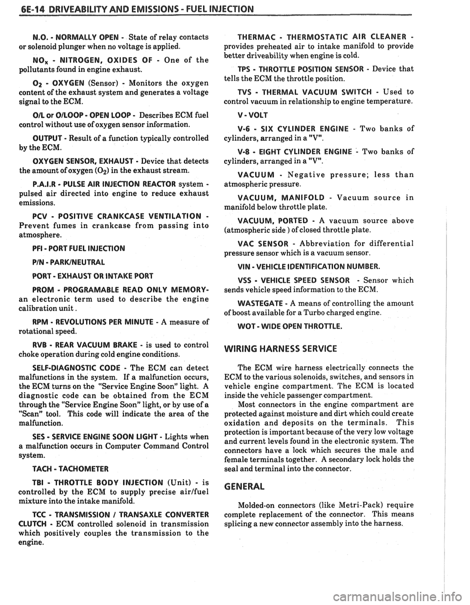
6E-14 DRIVEABILITY AND EMISSIONS - FUEL INJECTION
N.O. - NORMALLY OPEN - State of relay contacts
or solenoid plunger when no voltage
is applied.
NOx - NITROGEN, OXIDES OF - One of the
pollutants found in engine exhaust.
O2 - OXYGEN (Sensor) - Monitors the oxygen
content of the exhaust system and generates a voltage
signal to the ECM.
OIL or OILOOP - OPEN LOOP - Describes ECM fuel
control without use of oxygen sensor information.
OUTPUT - Result of a function typically controlled
by the ECM.
OXYGEN SENSOR. EXHAUST - Device that detects
the amount of oxygen
(02) in the exhaust stream.
P.A.1.R - PULSE AIR INJECTION REACTOR system -
pulsed air directed into engine to reduce exhaust
emissions.
PCV - POSITIVE CRANKCASE VENTILATION -
Prevent fumes in crankcase from passing into
atmosphere.
PFI - PORT FUEL INJECTION
PIN
- PARWNEUTWL
PORT - EXHAUST OR INTAKE PORT
PROM
- PROGRAMABLE READ ONLY MEMORY-
an electronic term used to describe the engine
calibration unit
.
RPM - REVOLUTIONS PER MINUTE - A measure of
rotational speed.
RVB - REAR VACUUM BMKE - is used to control
choke operation during cold engine conditions.
SELF-DIAGNOSTIC CODE - The ECM can detect
malfunctions in the system.
If a malfunction occurs,
the ECM turns on the "Service Engine Soon" light.
A
diagnostic code can be obtained from the ECM
through the "Service Engine Soon" light, or by use of a
"Scan" tool. This code will indicate the area of the
malfunction.
SES - SERVICE ENGINE SOON LIGHT - Lights when
a malfunction occurs in Computer Command Control
system.
TACH - TACHOMETER
TBI
- THROTTLE BODY INJECTION (Unit) - is
controlled by the ECM to supply precise airlfuel
mixture into the intake manifold.
TCC - TWNSMISSION I TRANSAXLE CONVERTER
CLUTCH
- ECM controlled solenoid in transmission
which positively couples the transmission to the
engine.
THERMAC - THERMOSTATIC AIR CLEANER -
provides preheated air to intake manifold to provide
better driveability when engine
is cold.
TPS - THROnLE POSITION SENSOR - Device that
tells the ECM the throttle position.
TVS - THERMAL VACUUM SWITCH - Used to
control vacuum in relationship to engine temperature.
V - VOLT
V-6 - SIX CYLINDER ENGINE - Two banks of
cylinders, arranged in a
"V".
V-8 - EIGHT CYLINDER ENGINE - Two banks of
cylinders, arranged in a
"V".
VACUUM - Negative pressure; less than
atmospheric pressure.
VACUUM, MANIFOLD - Vacuum source in
manifold below throttle plate.
VACUUM, PORTED - A vacuum source above I (atmospheric side ) of closed throttle plate. , I
WAC SENSOR - Abbreviation for differential
pressure sensor which is a
vacuum sensor.
VIN - VEHICLE IDENTIFIUTION NUMBER. 1
VSS - VEHICLE SPEED SENSOR - Sensor which
sends vehicle speed information to the ECM.
WASTECATE - A means of controlling the amount
of boost available for a Turbo charged engine.
WOT- WIDE OPEN THROPTLE. I
WIRING HARNESS SERVICE I
The ECM wire harness electrically connects the
ECM to the various solenoids, switches, and sensors in
vehicle engine compartment. The ECM is located
inside the vehicle passenger compartment.
Most connectors in the engine compartment are
protected against moisture and dirt which could create
oxidation and deposits on the terminals. This
protection is important because of the very low voltage
and current levels found in the electronic system. The
connectors have a lock which secures the male and
female terminals together. A secondary lock holds the
seal and terminal into the connector.
GENERAL
Molded-on connectors (like Metri-Pack) require
complete replacement of the connector. This means
splicing a new connector assembly into the harness.
Page 1163 of 1825
7C-6 CLUTCH
6. Clutch master cylinder push rod to clutch pedal.
7. Install brake switch.
8. Install hush panel.
9. Install steering column trim cover.
10. Install clutch reservoir to bracket.
1 1. Hoist vehicle.
12. Pilot slave cylinder into clutch fork.
NOTICE: With a new system, the slave cylinder
contains a shipping strap that pre-positions the
push rod for installation, and also provides a
bearing insert.
Follojving installation of the slave
cylinder, the first actuation of the clutch pedal will
break the shipping strap and give
normal system
operation.
13. Install slave cylinder and heat shield to bell
housing.
14.
Lojver vehicle.
15. Connect negative battery cable.
CLUTCH ASSEMBLY
Removal
1. Remove the transmission as outlined in
transmission section.
2. Remove the slave cylinder heat shield and slave
cylinder
from flywheel housing.
3. Reniove the flywheel housing.
4. Slide clutch fork from ball stud and remove fork
from dust boot. Ball stud is threaded into clutch
housing and is easily replaced, if necessary.
5. Install Tool 5-33169 to support the clutch
assen~bly during removal. Look for mark or white
painted letter on clutch cover and
"X" mark on
flywheel. If
"Xu or letter is not evident, mark
flywheel and clutch cover for indexing purposes
during installation.
6. Loosen clutch-to-flywheel attaching bolts evenly
1 turn at a time until spring pressure is released.
7. Remove clutch and pressure plate assembly.
lnspection
Inspect the flywheel for cracks, heat checking or
other defects. Replace or repair as required.
Installation
Pressure plate and flywheel face, (They should be
free of oil, grease, metal deposits or burned spots.)
Installation
1. Position clutch disc and pressure plate in relative
installed position and support them with
alignment Tool J-33169 or a drive gear.
The driven disc is installed with the damper
springs to the transmission. The flywheel side is
marked.
2. Turn clutch assembly until "X" mark or white
painted letter on cover lines up with
"X" mark on flywheel,
then align cover bolt holes to nearest
flywheel holes.
3. Install a bolt in every hole and tighten down
evenly and gradually until tight to avoid possible
clutch distortion. (Cover loads are as high as
1- 1/4 tons).
4. Remove the pilot tool.
5. Unhook clutch fork and lubricate ball socket and
fork fingers at release bearing end with a high
melting point grease such as graphite and
reinstall fork on ball stud.
6. Lubricate recess on inside of release bearing
collar and the clutch fork groove with light coat
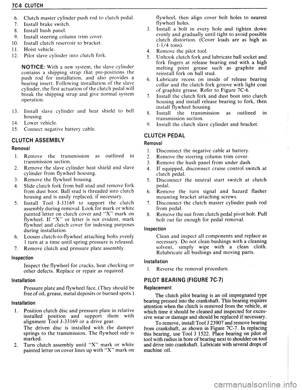
of graphite grease. Refer to Figure 7C-6.
7. Install the clutch fork and dust boot into clutch
housing and install release bearing to fork, then
install flywheel housing.
8. Install the transmission as outlined in
transmission section.
9. Install the clutch slave cylinder and bracket.
CLUTCH PEDAL
Removal
Disconnect the negative cable at battery.
Remove the steering column trim cover.
Remove the hush panel from under dash.
If equipped, disconnect cruise control switch at
clutch pedal.
Disconnect the neutral start switch at clutch
pedal.
Renlove the turn signal and hazard flasher
mounting bracket attaching screws.
Disconnect the clutch master cylinder push rod
from pedal.
Remove the nut from clutch pedal pivot bolt. Pull
bolt out far enough for pedal removal.
Inspection
Clean and inspect all components and replace as
necessary. Do not clean bushings with a cleaning
solvent, simply wipe with a clean cloth.
Relubricate all bushings and moving parts.
Installation
1. Reverse the removal procedure.
PILOT BEARING (FIGURE 7C-7)
Replacement
The clutch pilot bearing is an oil impregnated type
bearing pressed into the crankshaft. This bearing requires
attention when the clutch is removed from the vehicle, at
which time it should be cleaned and inspected for exces-
sive wear or damage and should be replaced if necessary.
To remove, install Tool
J 23907 and remove bearing
from crankshaft, as shown in Figure
7C-7. In replacing
this bearing, use Tool
J 1522. Place bearing on pilot of
tool with radius in bore of bearing next to shoulder on tool
and drive into crankshaft. Lubricate with several drops of
machine oil.
Page 1327 of 1825
CRUISE CONTROL
(Continued from previous page)
TEST I: RIA CIRCUIT OPEN
Disconnect C223 and check switch continuity
between terminals A (BLU) and C (YEL) of the
pin half of the Cruise Switch in RIA.
0 If the switch is open, replace the Multi-Func-
tion Lever.
If the switch is not open, check for an open in
the
GRYIBLK (87) wire between terminal C
of connector C223 at terminal M of the Mod-
ule.
TEST J: VENT CIRCUIT SHORT
Remove the connector from the Servo and mea-
sure resistance between terminals
A and C of
the Servo.
If it is less than 30 ohms, replace the Servo.
If it is 30 ohms or more, check for a short to
ground in the DK
BLUIWHT wire from ter-
minal C of the Module to terminal A of the
Servo.
TEST K: VSS ClRCUlT OPEN
If the VSS light does not come on, or the volt-
age between terminals A (GRY) and D (BRN)
remains less than 7 volts, check for an open in
the BRN (437) wire or the RED (381) wire from
the Vehicle Speed Sensor Buffer. Refer to page
33-0 for diagnosis of Vehicle Speed Sensor.
TEST L: VSS CIRCUIT SHORT
If the VSS lights does not go off or Battery
voltage remains between ter
and D
(BRN), check for a short to ground on the
BRN (437) wire or the RED (381) wire from the
Vehicle Speed Sensor Buffer. Refer to page 33-0
for diagnosis of Vehicle Speed Sensor.
TEST M: VACUUM SYSTEM
1. Check for a blocked or leaking vacuum
source.
2. If the vacuum source is good, plug the Vac-
uum Release Port and repeat Test
6 of the
Isolation Test.
If the vacuum now holds the throttle open,
replace or repair the Vacuum Release Valve
or the hose to it.
If the test still fails, replace the Cruise Con-
trol Servo.
TEST N: SPS CIRCUIT SHORT
Disconnect the Cruise Control Servo connector
and repeat Test 7 of the Isolation Test.
If the resistance is now over range, replace
the Cruise Control Servo.
If the resistance is still low, find and repair
the short in the TAN wire from terminal F of
the Cruise Control Module to terminal B of
the Cruise Control Servo.
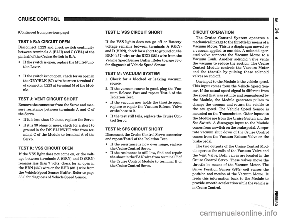
ClRCUlT OPERATION
The Cruise Control System operates a
mechanical linkage to the throttle by means of a
Vacuum Motor. This is a diaphragm moved by
a vacuum applied to one side. A solenoid oper-
ated valve connects the Vacuum Motor to a
Vacuum Tank. Another solenoid valve vents
the vacuum to reduce the suction. The Cruise
Control Module controls the Vacuum Motor
and the throttle by pulsing these solenoid
valves on and off.
One input to the Module is the vehicle speed.
This input comes from the Vehicle Speed Sen-
sor. If the actual speed signal is different from
the speed that was set into and remembered by
the Module, the Module generates pulses to
change the vacuum and return the vehicle to
the set speed. The Vehicle Speed Sensor is
mounted on the Transmission. Other inputs to
the Module are from the Cruise Switch and the
Set Switch. A disengage input to the Module
comes from a switch on the brake pedal. A
sepe-
rate vacuum shut down of the Cruise Control
comes from the Vacuum Release Valve on the
brake pedal.
The two outputs of the Cruise Control Mod-
ule operate the coils of the Vacuum Valve and
the Vent Valve. Both valves are located in the
Cruise Control Servo. These valves move the
throttle be means of the Vacuum Motor. The
Servo Position Sensor
(SPS) coil senses the
position and motion of the Vacuum Motor. It
feeds this information back to the Module to
provide smooth acceleration while the vehicle is
in Cruise Control.
Page 1475 of 1825
EXTERIOR LlGHTS
(Continued from previous page)
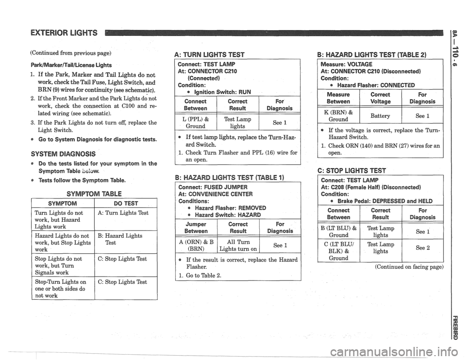
Park/MarkerflaIl/License UgMs
1. If the Park, Marker and Tail Lights do not
work, cheek the Tail Fuse, Light Switch, and
BRN (9) wires for continuity (see schematic).
2. If the Front Marker and the Park Lights dd not
work, check the connection at 6100 and re-
lated wiring (see schematic).
3. If the Park Lights do not turn off, replace the
Light Switch.
s Go to System Diagnosis for diagnostic tests.
@ Do the tests listed for your symptom in the
Symptom
Able bezaw.
@ Tests follow the Symptom Table.
SYMPTOM arABhE
A: TURN LIGHTS TEST
SYMPTOM
Turn Lights do not
work, but Hazard
Lights work
Hazard Lights do not
work, but Stop Lights
work
Stop Lights do not
work, but Turn
Signals work
Stop-Turn Lights on
one or both sides do
not work
B: HAZARD LIGHTS TEST (TABLE 2)
DO TEST
A: Turn Lights Test
B: Hazard Lights
Test
6: Stop Lights Test
6: Stop Lights Test
Connect: TEST LAMP
At: CONNECTOR C210
(Connected)
Condition:
Ignition Switch: RUN
o If the result is correct, replace the Hazard
Flasher.
1. Go to Table 2.
B: HAZARD LIGHTS TEST (TABLE 1)
Connect: FUSED JUMPER
At: CONVENIENCE
CENTER
Conditions:
r Hazard Flasher: REMOVED
Hazard Switch:
HAZARD
Measure: VOLTAGE
At: CONNECTOR 621 0 (Disconneded)
Condition:
Hazard Flasher: CONNECTED
For
Diagnosis
See 1
Connect
Between
L (PPL) &
Ground
I Measure ( Correct ( For
e If test lamp lights, replace the
ard Switch.
1. Check Turn Flasher and PPE (16) wire for
an open.
Correct
Result
Test Lamp
lights
For
Diagnosis
See 1
Jumper
Between
A (QRN) & B
(BRN)
Between I Voltage I Diagnosis
Correct Result
All Turn
Lights turn on
( If the voltage is correct, replace the Turn- I
(BRN) &
Ground
Hazard Switch.
1. Check ORN (140) and BRN (27) wires for an
open.
6: STOP LIGHTS TEST
At: 6208 (Fernale Half) (Disconnected)
Condition:
Brake Pedal: DEPRESSED and HELD
Battery See 1
Connect
Behvveen
I CEKyy 1 Test Lamp
lights I See 2 I
B (LT BLU) &
Ground
I Ground I I I
Correct
Result
(Continued on facing page)
For
Diagnosis
Test Lamp
lights See 1
Page 1477 of 1825
EXTERIOR LIGHTS I$
(Continued from previous page)
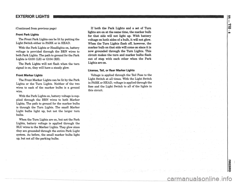
Front Park Lights
The Front Park Lights can be lit by putting the
Light Switch either in
PARK or in HEAD.
With the Park Lights or Headlights on, battery
voltage is provided through the BRN wires to
both Park Lights. The path to ground for the Park
Lights is
6103 (LH) or 6104 (RN).
The Park Lights will not flash when the turn
signal is on, they will have a steady glow.
Front Marker Lights
The Front Marker Lights can be lit by the Park
Lights or the Turn Lights. Neither of the two
wires to each of the marker bulbs is
a ground
wire.
With the Park Lights on, battery voltage is sup-
plied through the BRN wires to both Marker
Lights. The path
to ground for the marker bulbs
is through the
Turn Lights. The small Marker
Light bulbs light up, but not the larger turn
bulbs.
Lights are on, but not the Park
Lights, battery voltage is applied through the
BLU wires
to the Marker Lights. They glow since
they are grounded through the entire Park Light
system. As before, the small marker bulbs light
up, but not all the parking bulbs. If
both the Park Lights and a set of
lights are on at the same time, the marker
for that side
will not light up. With battery
voltage on both sides of
a bulb, it will not glow.
When the Lights flash off, however, the
marker bulb on that side will come on since
it is
now grounded through the Lights. This
circuit
makes the turn and marker bulbs flash
out of step with each other when the Park
Lights are on.
License, Tail, or Rear Marker Lights
Voltage is applied through the Tail Fuse to the
Light Switch at all times. With the Light Switch
in PARK or
HEAD, voltage is applied through the
fuse and the Light Switch to all of the lights in
this circuit.