alarm PONTIAC FIERO 1988 Service User Guide
[x] Cancel search | Manufacturer: PONTIAC, Model Year: 1988, Model line: FIERO, Model: PONTIAC FIERO 1988Pages: 1825, PDF Size: 99.44 MB
Page 1600 of 1825
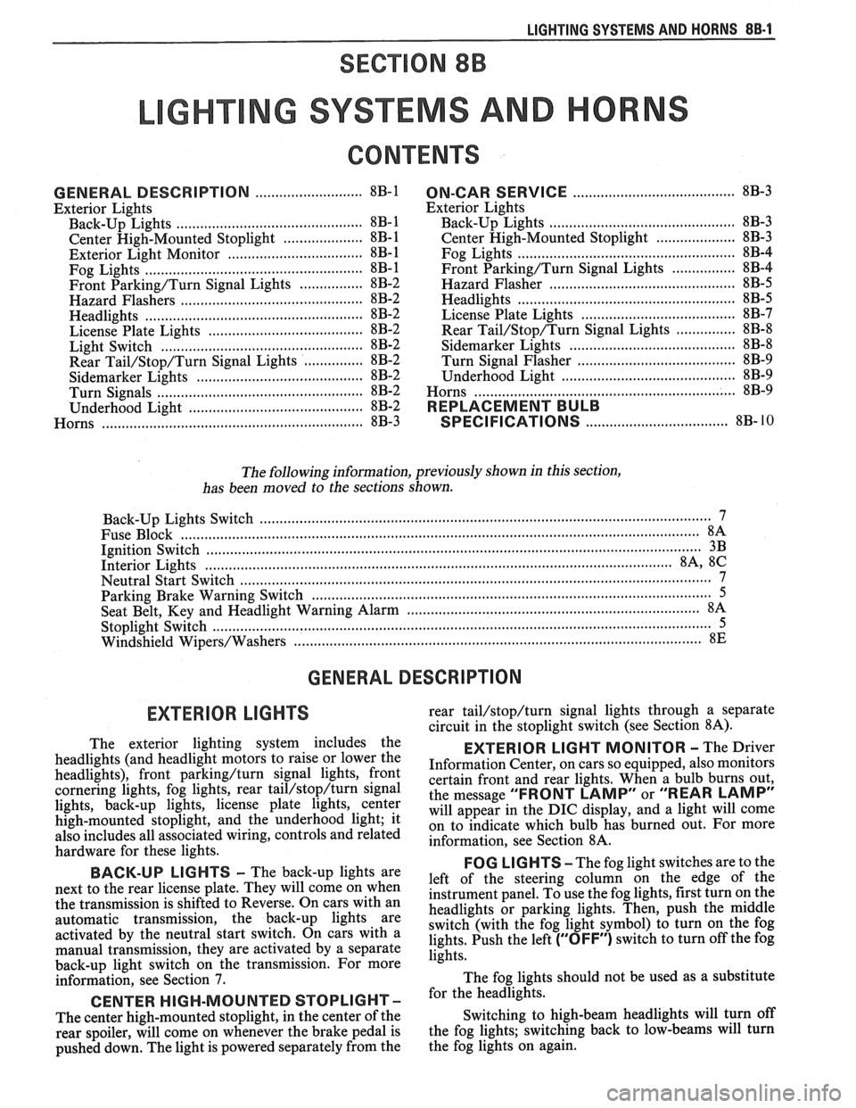
LIGHTING SYSTEMS AND HORNS 8B-I
SECTION 8B
NG SYSTEMS AND HORNS
CONTENTS
........................... GENERAL DESCRIPTION 8B-1
Exterior Lights
....................... ................... Back-up Lights .. 8B- 1
Center High-Mounted Stoplight .................... 8B-1
Exterior Light Monitor .................................. 8B-1
............................ .................... Fog Lights .. 8B-1
Front Parking/Turn Signal Lights ................ 8B-2
............................... Hazard Flashers .. ........ 8B-2 .................................................... Headlights 8B-2
License Plate Lights ..................................... 8B-2
Light Switch ............................................... 8B-2
............... Rear Tail/Stop/Turn Signal Lights 8B-2
Sidemarker Lights ........................................ 8B-2
Turn Signals .......................................... 8B-2
......................... Underhood Light ... ........ 8B-2
Horns .......................................................... 8B-3
....................................... ON-CAR SERVICE 8B-3
Exterior Lights
............................................. Back-up Lights 8B-3
Center High-Mounted Stoplight .................... 8B-3
Fog Lights .................................................... 8B-4
Front Parking/Turn Signal Lights ................ 8B-4
Hazard Flasher .............................................. 8B-5
....................................................... Headlights 8B-5
License Plate Lights ..................................... 8B-7
............... Rear Tail/Stop/Turn Signal Lights 8B-8
.......................................... Sidemarker Lights 8B-8
................... ............... Turn Signal Flasher .. 8B-9
......................................... Underhood Light 8B-9
Horns ................................................................. 8B-9
REPLACEMENT BULB
.................................... SPECIFICATIONS 8B- 10
The following information, previously shown in this section,
has been moved to the sections shown.
Back-up Lights Switch
............................. ... ............................................................................ 7
................................................................................................................................. Fuse Block 8A
Ignition Switch ........................................................................................................................... 3B
Interior Lights
................................................................................................................... 8A, 8C
Neutral Start Switch ..................................................................................................................... 7
Parking Brake Warning Switch
......................... ... .................................................................... 5
........................................................................ Seat Belt, Key and Headlight Warning Alarm 8A
Stoplight Switch .......................... .. ............................................................................................... 5
Windshield
Wipers/Washers .................................................................................................... 8E
GENERAL DESCRIPTION
The exterior lighting system includes the
headlights (and headlight motors to raise or lower the
headlights), front
parkinghurn signal lights, front
cornering lights, fog lights, rear
tail/stop/turn signal
lights, back-up lights, license plate lights, center
high-mounted stoplight, and the underhood light; it
also includes all associated wiring, controls and related
hardware for these lights.
BACK-UP LIGHTS - The back-up lights are
next to the rear license plate. They will come on when
the transmission is shifted to Reverse. On cars with an
automatic transmission, the back-up lights are
activated by the neutral start switch. On cars with a
manual transmission, they are activated by a separate
back-up light switch on the transmission. For more
information, see Section 7.
CENTER HIGH-MOUNTED STOPLIGHT-
The center high-mounted stoplight, in the center of the
rear spoiler, will come on whenever the brake pedal is
pushed down. The light is powered separately from the rear
tail/stop/turn signal
lights through a separate
circuit in the stoplight switch (see Section
8A).
EXTERIOR LIGHT MONITOR - The Driver
Information Center, on cars so equipped, also monitors
certain front and rear lights. When a bulb burns out,
the message
"FRONT LAMP" or "REAR LAMP"
will appear in the DIC display, and a light will come
on to indicate which bulb has burned out. For more
information, see Section
8A.
FOG LIGHTS -The fog light switches are to the
left of the steering column on the edge of the
instrument panel. To use the fog lights, first turn on the
headlights or parking lights. Then, push the middle
switch (with the fog light symbol) to turn on the fog
lights. Push the left
("OFF") switch to turn off the fog
lights.
The fog lights should not be used as a substitute
for the headlights.
Switching to high-beam headlights will turn off
the fog lights; switching back to low-beams will turn
the fog lights on again.
Page 1784 of 1825
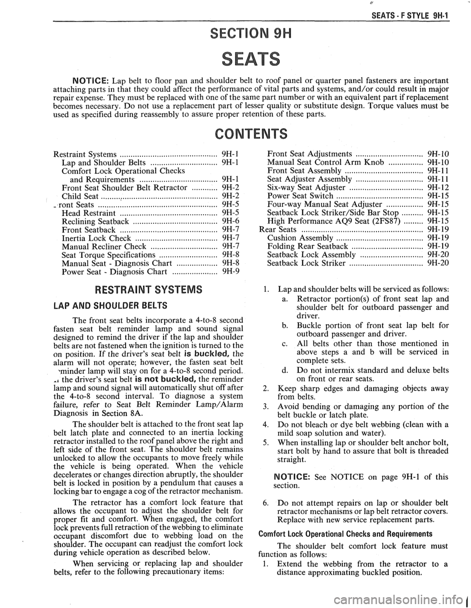
SEATS - F STYLE 9H-1
SEC"IC"0N 9H
SEATS
NOTICE: Lap belt to floor pan and shoulder belt to roof panel or quarter panel fasteners are important
attaching parts in that they could affect the performance of vital parts and systems, and/or could result in major
repair expense. They must be replaced with one of the same part number or with an equivalent part if replacement
becomes necessary. Do not use a replacement part of lesser quality or substitute design. Torque values must be
used as specified during reassembly to assure proper retention of these parts.
CONTENTS
Restraint Systems ........................................... 9H- 1
Lap and Shoulder Belts
............................... 9H-1
Comfort Lock Operational Checks
and Requirements
.................................... 9H- 1
Front Seat Shoulder Belt Retractor
............ 9H-2
Child Seat
...................................................... 9H-2
............................... .................. -.rant Seats .. 9H-5
Mead Restraint
............................................. 9H-5
Reclining
Seatback ................................... 9H-6
Front
Seatback ........................................... 9H-7
Inertia Lock Check
...................................... 9H-7
............................... Manual Recliner Check 9H-7
........................... Seat Torque Specifications 9H-8
Manual Seat
- Diagnosis Chart ................... 9H-8
..................... Power Seat - Diagnosis Chart 9H-9
RESTRAINT SYSTEMS
LAP
AND SHOULDER BELTS
The front seat belts incorporate a 4-to-8 second
fasten seat belt reminder lamp and sound signal
designed to remind the driver if the lap and shoulder
belts are not fastened when the ignition is turned to the
on position. If the driver's seat belt
is buckled, the
alarm will not operate; however, the fasten seat belt
xminder lamp will stay on for a 4-to-8 second period.
,, the driver's seat belt is not buckled, the reminder
lamp and sound signal will automatically shut off after
the 4-to-8 second interval. To diagnose a system
failure, refer to Seat Belt Reminder
Lamp/Alarm
Diagnosis in Section 8A.
The shoulder belt is attached to the front seat lap
belt latch plate and connected to an inertia locking
retractor installed to the roof panel above the right and
left side of the front seat. The shoulder belt remains
unlocked to allow the occupants to move freely while
the vehicle is being operated. When the vehicle
decelerates or changes direction abruptly, the shoulder
belt is locked in position by a pendulum that causes a
locking bar to engage a cog of the retractor mechanism.
The retractor has a comfort lock feature that
allows the occupant to adjust the shoulder belt for
proper fit and comfort. When engaged, the comfort
lock prevents full retraction of the webbing to eliminate
occupant discomfort due to webbing load on the
shoulder. The occupant can readjust the comfort lock
during vehicle operation as described below.
When servicing or replacing lap and shoulder
belts, refer to the following precautionary items: Front
Seat Adjustments
............................... 9H- 10
Manual Seat Control Arm Knob
................ 9H-10
Front Seat Assembly
.................................... 9H- 1 1
Seat Adjuster Assembly ............................. 9H-11
Six-way Seat Adjuster .................................. 9H- 12
Power Seat Switch
........................................ 9H-15
Four-way Manual Seat Adjuster
................. 9H-15
Seatback Lock Striker/Side Bar Stop .......... 9H-15
High Performance AQ9 Seat
(2FS87) ......... 9H-15
................. .................................... Rear Seats ... 9H- 19
........................................ Cushion Assembly 9H- 19
................................ Folding Rear Seatback 9H- 19
........................... Seatback Lock Assembly 9H-20
.................................. Seatback Lock Striker 9H-20
1. Lap and shoulder belts will be serviced as follows:
a. Retractor
portion(s) of
front seat lap and
shoulder belt for outboard passenger and
driver.
b. Buckle portion of front seat lap belt for
outboard passenger and driver.
c. All belts other than those mentioned in
above steps a and b will be serviced in
complete sets.
d. Do not intermix standard and deluxe belts
on front or rear seats.
2. Keep sharp edges and damaging objects away
from belts.
3. Avoid bending or damaging any portion of the
belt buckle or latch plate.
4. Do not bleach or dye belt webbing (clean with a
mild soap solution and water).
5. When installing lap or shoulder belt anchor bolt,
start bolt by hand to assure that bolt is threaded
straight.
NOTICE: See NOTICE on page 9H-1 of this
section.
6. Do not attempt repairs on lap or shoulder belt
retractor mechanisms or lap belt retractor covers.
Replace with new service replacement parts.
Comfort Lock Operational Checks and Requirements
The shoulder belt comfort lock feature must
function as follows:
1. Extend the webbing from the retractor to a
distance approximating buckled position.
Page 1818 of 1825
Battery .......................................................... 6D1-2
Brakes
.................................................................. 5-3
................................ Bumper. Energy Absorber 2B-2
........................................... Charging System 6D3- 1
........................................ Cooling and Radiator 6B-3
....................... ................ Cranking System .. 6D2- 1
Cruise Control
................................. 9B-4, 8A-34-0
......................................... Drive Axles (Rear) 4B1-2
Engine Performance
......................................... 6-3
.............................................. Ignition System 6D4-3
Instrument Panel, Gages and
.................................................... Console 8C-3
............................. Miscellaneous Accessories 9G-2
............................................... Power Antenna 9A-2
Power Recirculation Ball
.................................. 3-3
Power Steering Pumps
........................................ 3-4
.............................................. Propeller Shaft 4A- 1
................................................................ Radio 9A-1
.............. Seal Replacement Recommendations 3- 10
........................ . Steering Gear and Pump Leaks 3-10
.............. Strut Dampener and Shock Absorber 3- 12
.................................................... Trim
Height 3- 14
.................................................. Steering Linkage 3-3
Steering, Suspension, Tires and
Wheels
.............................. .. ................. Section 3
Steering Wheels and Columns
............................ 3-4 ......................................................... Vibrations 3- 14
................................................. Wheel Bearing 3-14 .............................................. Wheels and Tires 3- 13
........................... Windshield Wiper System 8El-2
............................................. Digital Cloclc 8A- 150-0
Disc Brake Caliper Assembly
.......................................... (3000/3 100 Series) 5B1
............... ................... General Description .. 5B 1-2 ............................................... On-Car Service 5B 1-2
...................................... Caliper Assembly 5B 1-2
.......................... Shoe and Lining Assembly 5B 1-4
...................................................... Unit Repair
5B 1-4
.......................................... Caliper Overhaul 5B 1-4
?isc Brake Caliper Assembly (3548
Series)
............................................................. 5B6
General Description
....................................... 5B6-2
On-Car Service
............................................... 5B6-2
....................................... Caliper Assembly 5B6-2
.......................... Parking Brake Adjustment 5B6-3
.......................... Shoe and Lining Assembly 5B6-4
Unit Repair
............................... ... .................... 5B6-5
Caliper Overhaul
.......................................... 5B6-5
.......................... Door Lock Relay (Circuit) 8A- 130-0
Driveability and Emissions
........................ Section 6E
Fuel Injection (Port)
..................................... 6E3-1
Index
................................... follows 6E3-(213-2
...................................... Fuel Injection (TB 1) .6E
2- 1
...................................... Index follows 6E2-C 14-4
Drum Brake Assembly
................... ......... Section 5C3
General Description
......................... ... ............ 5C3-1
........................................... On-Car Service 5C3- 1
Backing Plate
........................................ 5C3-7
....................................... Brake Adjustment .5C 3-4
..................................... Brake Components 5C3-1
Parking Brake Adjustment
.......................... 5C3-4
Wheel Cylinder ........................................... 5C3-5 ..................................................... Unit Repair 5C3-7
............................ Wheel Cylinder Overhaul 5C3-7
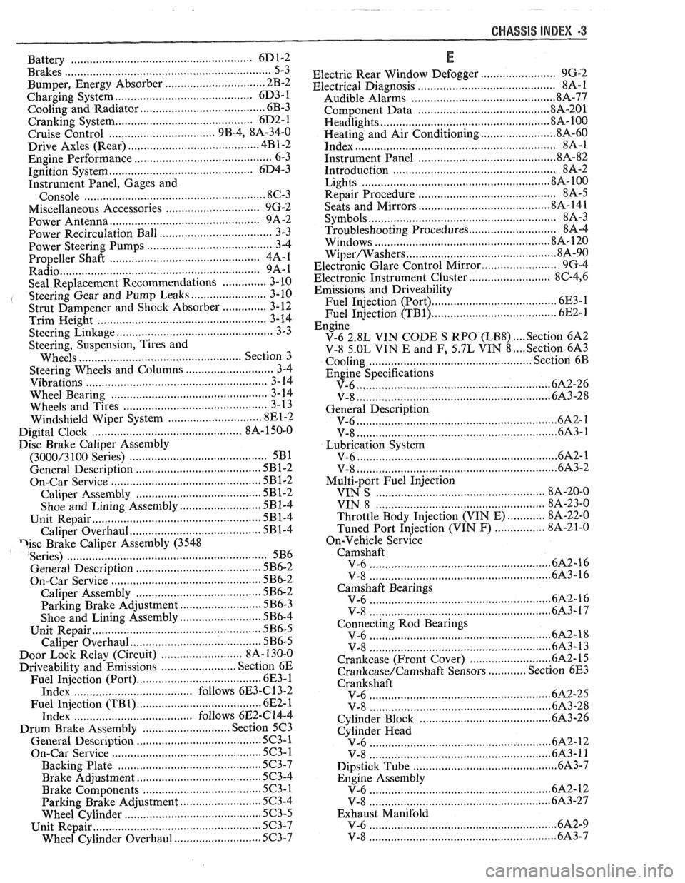
CHASSIS INDEX m3
E
........................ Electric Rear Window Defogger 9G-2 ............................................ Electrical Diagnosis 88-1
Audible Alarms .............................................. 81%-77
.......................................... Component Data 818-201
.................................................... Headlights 8A- 100
........................ Heating and Air Conditioning 8A-60 .............................................................. Index $A- 1
........................................... Instrument Panel .8 A-82
.................................................. Introduction 8A-2
........................................................... Lights .8 A- 100
............................................ Repair Procedure 88-5 ........................................ Seats and Mirrors 8A- 141
......................................................... Symbols 8A-3
Troubleshooting Procedures ............................ 8A-4
.................................................. ... Windows .. .8 A- 120
............................................... Wiper/Washers .8 A-90
Electronic Glare Control Mirror
........................ 9G-4
.......................... Electronic Instrument Cluster 86-4, 6
Emissions and Driveability
....................................... Fuel Injection (Port) 6E3- 1
....................................... Fuel Injection (TB1) 6E2-1
Engine
.... V-6 2.8L VIN CODE S RPO (LB8) Section 6A2
.... V-8 5.OL VIN E and F, 5.7L VIN 8 Section 6A3
................................................. Cooling Section 6B
Engine Specifications
............................................................ V-6 6A2-26
............................................................. V-8 683-28
General Description
.............................................................. V-6 61 ............................................................. V-8 6A3-1
Lubrication System ........................................................... V-6 ..6A 2- 1
................................................................ V-8 6A3-2
Multi-port Fuel Injection
..................................................... VIN S 8A-20-0
................................................. VIN 8 8A-23-0
............ Throttle Body Injection (VIN E) 8A-22-0
................ Tuned Port Injection (VIN F) 8A-2 1-0
On-Vehicle Service Camshaft
......................................................... V-6 6A2-16
................................ ..................... V-8 .. 6A3-16
Camshaft Bearings
......................................................... V-6 6A2-16
...................................................... V-8 ..6A 3-17
Connecting Rod Bearings
......................................................... V-6 .6A 2- 18
................................................... V-8 6A3-13
...................... Crankcase (Front Cover) .6A
2- 15
............ Crankcase/Camshaft Sensors Section 6E3
Crankshaft
....................................................... V-6 6A2-25
......................................................... V-8 .6A 3-28
......................................... Cylinder Block .6A 3-26
Cylinder Head
.......................................................... V-6 682-12
.......................................................... V-8 6A3-11
Dipstick Tube .............................................. 6A3-7
Engine Assembly
....................................................... V-6 6212
.......................................................... V-8 6A3-27
Exhaust Manifold
........................................................ V-6 .6A 2-9
V-8
....................................................... 6A3-7