radiator PONTIAC FIERO 1988 Service Repair Manual
[x] Cancel search | Manufacturer: PONTIAC, Model Year: 1988, Model line: FIERO, Model: PONTIAC FIERO 1988Pages: 1825, PDF Size: 99.44 MB
Page 22 of 1825
MAINTENANCE AND LUBRICATION OB-5
Throttle linkage inspection -- Inspect for inter-
ference, binding, damaged or missing parts.
Engine drive belts inspection - Inspect all
belts for cracks, fraying and wear. Adjust or replace as
needed.
Rear axle service (if equipped) - Check gear
lubricant level and add if needed. For cars equipped with a
limited slip rear axle, fluid does not require changing
(except Caprice and Corvette
- change fluid and required
additive at first
7,500 miles (12 500 km). See your
Owner's Manual or "Recommended Fluids
& Lubricants
Chart" in this section.
IF YOU USE YOUR GAR TO PULL A TRAILER,
CHANGE GEAR LUBRICANT EVERY 7,500 MILES
(12 500 KM).
NOTICE: A large loss in this system may indicate a
problem. Have it inspected and repaired at once.
Power antenna - Clean and then lubricate power
antenna mast. The proper lubricant as shown in Figure
OB-2 should be used.
AT LEAST ONCE A YEAR
Lap and shoulder belts condition and opera-
tion
- Inspect belt system, including webbing, buckles,
latch plates, retractors, guide loops and anchors.
Moveable head restraint operation - On cars
with moveable restraints, make sure restraints stay in the
desired position. (See adjustment instructions in your
Owner's Manual.)
Seatback latch and recliner operation on
cars equipped
with recliner seat --- Be sure seat-
backs latch on those cars with folding seats using mechan-
ical latches. Make sure the recliner is holding by pushing
and pulling on the top of the
seatback while it is reclined.
See your Owner's Manual for seat operating information.
Spare tire and jack storage- Be alert to rattles
in rear of car. Make sure the space tire, all jacking equip-
ment, any tire inflator and any covers or doors are securely
stowed at all times. Oil jack ratchet or screw mechanism
after each use.
Key lock service - Lubricate key lock cylinder at
least annually.
Body lubrication service - Lubricate all body
door hinges including the tailgate or hatchback lid (if
equipped). Also lubricate the body hood, fuel door and
rear compartment hinges and latches including interior
glove box and counsel doors, and any folding seat
hardware.
"Fansmissionltransaxle neutral or clutch
starl switch operation
CAUnON: Before pedorming the follow-
ing safety switch check, be sure to have
enough room around the car. Then, firmly
apply both the parking brake (see your
Owner's Manual for procedure) and the
regular brakes. Do not use the accelerator pedal.
If the engine
starls, be ready to turn
off the ignition promptly. Take these pre-
cautions because the car could move
without warning and possibly cause per-
sonal injury or properly damage. On auto-
matic transmissionltransaxle cars, try to
starl the engine in each gear. The starler
should crank only in "Park" or "Neutral."
On manual transmissionltransaxle cars,
place the
shiR lever in "Neutral," push the
clutch halfway and try to starl. The starler
should crank only when the clutch is fully
depressed.
Steering column lock operation
- While
parked, try to turn key to "Lock" in each gear range. The
key should turn to "Lock" only when gear is in "Park" on
automatic or "Reverse" on manual
transmissionltransax-
le. On cars with key release lever, try to turn key toULock"
without depressing the lever. The key should turn to
"Lock" only with the key lever depressed. On all vehicles,
the key should come out only in "Lock."
Parking brake and transmissionltransaxle
"Park" mechanism operation
CAUT1ON:Before checking the holding
ability of the parking brake and automatic
transmissionltransaxle "Park" mecha-
nism, park on a fairly steep hill with
enough room for movement in the down-
hill direction. To reduce the risk of person-
al injury or property damage, be prepared
to apply the regular brakes promptly if the
car begins to move.
To check the parking brake, with the engine running and
transmission/transaxle in "Neutral." slowly remove foot
pressure from the regular brake pedal (until the car is held
by only the parking brake).
To check the automatic transmissionltransaxle "Park"
mechanism holding ability, release all brakes after shift-
ing the transmissionltransaxle to "Park."
ljnderbody flushing - At least every spring,
tlush from the underbody with plain water any corrosive
materials used for ice and snow removal and dust control.
Take care to thoroughly clean any areas where mud and
other debris can collect.
Sediment packed in closed areas
of the vehicle should be loosened before being flushed.
Engine cooling system service - Inspect
coolant and freeze protection. If dirty or rusty, drain, flush
and refill with new coolant. Keep coolant
at the proper
mixture as specified in your Owner's Manual. This pro-
vides proper freeze protection. corrosion inhibitor level
and engine operating temperature. Inspect hoses and re-
place if cracked. swollen or deteriorated. Tighten hose
clamps. Clean outside of radiator and air conditioning
condensor. Wash radiator filler cap and neck.
To help
ensure proper operation. a pressure test of both the cooling
system and cap is also recommended. (See maintenance
schedule charts in Figure
OB-l for the recommended
coolant change interval.)
Page 28 of 1825
HEATING AND VENTILATION 1A-5
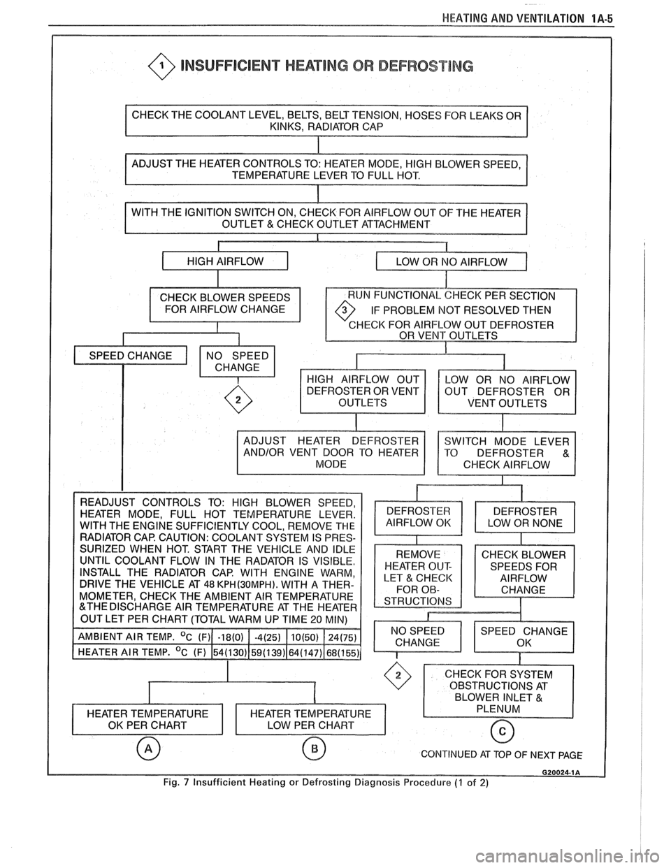
@ INSUFFICIENT HEATING OR DEFROST lNG
OF THE HEATER
IF PROBLEM
NOT RESOLVED THEN
HECK FOR AIRFLOW OUT DEFROSTER
VENT OUTLETS
INSTALL THE RADIATOR CAP. WITH ENGINE WARM,
DRIVE THE VEHICLE AT
48 KPH(3OMPH). WITH A THER-
MOMETER, CHECK THE AMBIENT AIR TEMPERATURE
CONTINUED AT TOP OF NEXT PAGE
Fig. 7 Insufficient Heating or Defrosting Diagnosis Procedure (7 of 2)
Page 45 of 1825
18-2 AIR CONDITIONING
SYSTEM GONIPONENE - FFUNCnIONAL
Compressor
All compressors are belt driven from the engine
crankshaft through the compressor clutch pulley. The
compressor pulley rotates without driving the com-
pressor shaft until an electromagnetic clutch coil is
energized. When voltage is applied to energize the
clutch coil, the clutch plate and hub assembly is
drawn rearward toward the pulley. The magnetic
force locks the clutch plate and pulley together as one
unit to drive the compressor shaft.
As the compressor shaft is driven, it compresses
the low-pressure refrigerant vapor from the evaporator
into a high-pressure, high-temperature vapor. Carried
with the refrigerant is the refrigerant oil which is used
to lubricate the compressor. Complete compressor
overhaul procedures can be found in Section
ID of the
General Service Manual.
Pressure Relief Valve
The compressor is equipped with a pressure
relief valve which is placed in the system as a safety
factor. Under certain conditions, the refrigerant on the
discharge side may exceed the designed operating
pressure. To prevent system damage, the valve is
designed to open automatically at approximately
3036
kPa (440 psi). Conditions that might cause this valve
to open (defective high pressure cut-off switch, inop-
erative electric cooling fan, etc.) should be corrected,
and the refrigerant oil and refrigerant should be
replaced as necessary.
A muffler is used on some refrigerant systems to
reduce compressor noises from high or low pressure
vibrations.
Condenser Gore
The condenser assembly in front of the radiator
is made up of coils which carry the refrigerant TO
cooling fins to provide rapid transfer of heat. The air
passing through the condenser cools the high-pressure
refrigerant vapor causing it to condense to a liquid.
Expansion (Orifice) Tube
The plastic expansion tube, with its mesh screen
and orifice, is located in the evaporator inlet pipe at
the liquid line connection. It provides a restriction to
the high-pressure liquid refrigerant in the liquid line,
metering the flow of refrigerant to the evaporator as a
low-pressure liquid. The expansion tube and orifice
are protected from contamination by filter screens on
both inlet and outlet sides. The tube is serviced only
as a replacement assembly.
When the engine is turned "OFF" with the
A/C
system operating, the refrigerant in the system will
flow from the high-pressure side of the expansion tube (orifice) to the low-pressure side until the pressure
is
equalized. This may be detected as a faint sound of
liquid flowing (hissing) for 30 to
60 seconds and is a
normal condition.
Evaporator Gore
The evaporator is a device which cools and
dehumidifies the air before it enters the car. High-
pressure liquid refrigerant flows through the expan-
sion tube (orifice) into the low-pressure area of the
evaporator. The heat in the air passing through the
evaporator core is transferred to the cooler surface of
the core, thereby cooling the air. As the process of
heat transfer from the air to the evaporator core sur-
face is taking place, any moisture (humidity) in the air
condenses on the outside surface of the evaporator
core and is drained off as water.
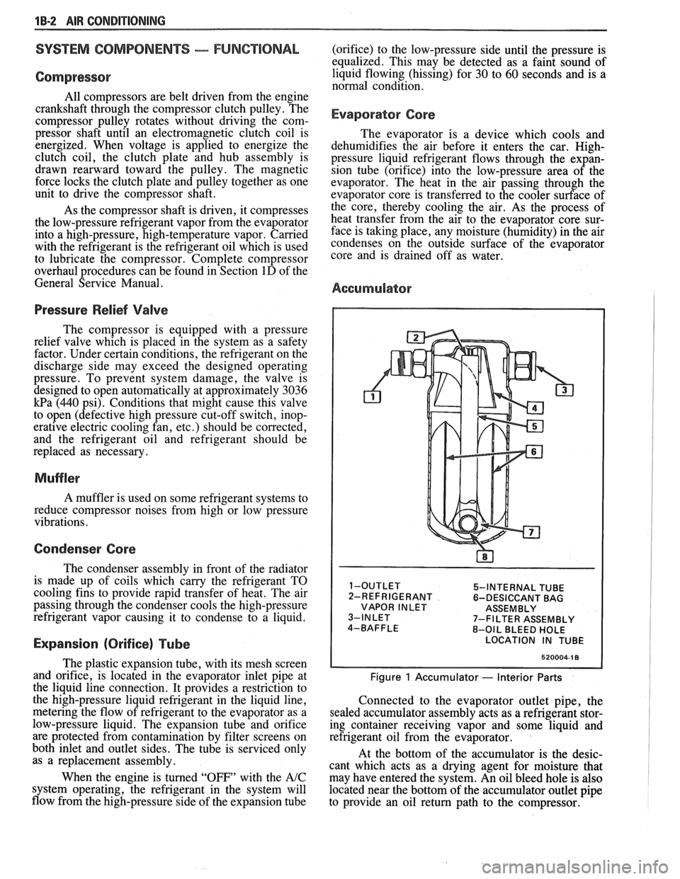
Accumulator
5-INTERNAL TUBE
2-REFRIGERANT 6-DESICCANT BAG
VAPOR INLET ASSEMBLY
7-FILTER ASSEMBLY
8-OIL BLEED HOLE
LOCATION IN TUBE
520004-1 8
Figure 1 Accumulator - Interior Parts
Connected to the evaporator outlet pipe, the
sealed accumulator assembly acts as a refrigerant stor-
ing container receiving vapor and some liquid and
refrigerant oil from the evaporator.
At the bottom of the accumulator is the desic-
cant which acts as a drying agent for moisture that
may have entered the system. An oil bleed hole is also
located near the bottom of the accumulator outlet pipe
to provide an oil return path to the compressor.
Page 48 of 1825
AIR CONDITIONING 113-5
DIAGNOSIS
TESTING THE REFRIGERANT SYSEEM
If a malfunction in the refrigerant system is sus-
pected, check the following:
1. Check outer surfaces of radiator and condenser
cores to be sure air flow is not blocked by dirt,
leaves or other foreign material. Be sure to
check between the condenser and radiator as
well as the outer surfaces.
2. Restrictions or kinks in the condenser core,
hoses, tubes, etc.
3. Blower fan operation (see Section 8A).
4. Check all air ducts for leaks or restrictions. Low
air flow rate may indicate a restricted evaporator
core.
5. Compressor clutch slippage.
6. Improper drive belt tension.
7. See C.C.O.T. AIC system diagnostic
procedures.
InsufFicient Cooling "Quick-Check"
Procedure
The following "HAND-FEEL" procedure can
be used to approximate whether or not the
AIC system
has the proper charge of Refrigerant- 12 (providing air
temperature is above
2 1°C [70°F])on most models. This check can
be made in a matter of minutes and
may simplify system diagnosis by pinpointing the
problem to the amount of
W- 12 charge in the system or
by eliminating low charge possibility from the overall
checkout.
1. Engine must be
warm(CH0KE OPEN and OFF
FAST IDLE SPEED CAM) and at normal idle
speed.
2. Hood and body doors open.
3. Selector (mode) button set at "NORM."
4. Temperature lever at full COLD.
5. Blower on "HI."
6. "Hand-Feel" temperature of evaporator inlet
pipe after orifice, and accumulator surface, with
compressor engaged.
BOTH SAME TEMPERATURE AND
BOTH SAME DEGREE COOLER
THAN AMBIENT
- Proper condition:
check for other problems; (see Testing the
Refrigerant System).
@ Leak check. If leak found, dis-
charge and repair as required. Evac-
uate and recharge.
e If no leak found, see A/C System
Diagnostic Procedures.
EVAPORATOR
'MODE POSITION
INDICATED
BY (
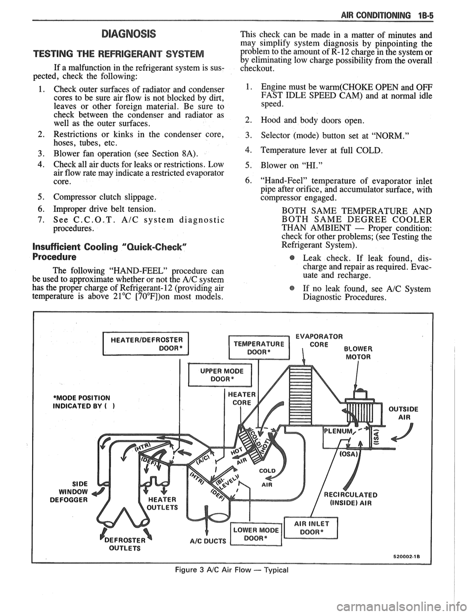
Figure 3 AIC Air Flow --- Typical
Page 67 of 1825
1B-24 AIR CONDPTIBNING
EVAPORATOR CORE
Remove QP Disconnect
1. Discharge A/C system.
2. Remove accumulator.
3. Remove two (2) screws and remove hi-blower
relay terminal.
4. Remove upper case screws.
5. Relocate wiring harness and remove dipstick.
6. Disconnect liquid line fitting.
7. Remove upper case and lift evaporator core out
of case (retain foam wedge).
Install or Connect
1. Reverse removal procedure to reinstall.
2. Recharge and test system for proper operation.
EVAPBRAWORCASE
Remove or Disconnect
1. Remove accumulator.
2. Remove blower motor.
3. Remove evaporator core.
Remove lower case to cowl screws (three driven from engine compartment, three driven from
interior).
Remove case from cowl.
Install or Connect
Reverse removal procedure to reinstall. Rein-
stall or replace gaskets, seal and sealant
removed during disassembly.
Recharge and test system for proper operation.
NG COMPRESSOR (TYPICAL)
Remove or Disconnect
1. Discharge A/C system.
2. Remove fitting block (coupled hose assembly)
bolt at rear of compressor.
3. Remove mounting bracket bolt(s) .
4. Remove drive belt (route lower loop behind har-
monic balancer to gain additional slack if
required).
5. Remove compressor. If complete compressor is
to be replaced, transfer usable switches, etc. to
new compressor.
Install or Connect
1. Reverse removal
procedure to reinstall. Use
new O-rings lubricated with
525 viscosity
refrigerant oil. Refer to Section
6B for drive belt
tension.
2. Evacuate and recharge system.
CONDENSER
a Remove or Disconnect
1. Discharge A/C system.
2. Disconnect coupled hose and liquid line fittings.
3, Remove screws retaining top radiator shield.
4. Remove top condenser retaining screws.
5. Carefully move (tilt) radiator rearward and lift
condenser out of radiator support.
6. Transfer brackets and mounts to new condenser
if replacement is necessary.
Install or Connect
1. Reverse removal procedure to reinstall. Use
new O-rings lubricated with
525 viscosity
refrigerant oil.
2. Recharge and test system for proper operation.
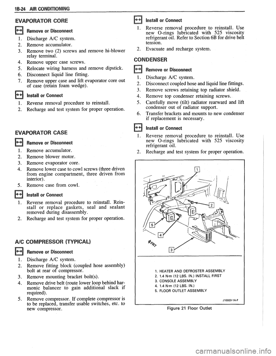
1. HEATER AND DEFROSTER ASSEMBLY
2. 1.4
N.m (12 LBS. IN.) INSTALL FIRST
3. CONSOLE ASSEMBLY
4.
1.4 Narn (12 LBS. IN.)
5. FLOOR OUTLET ASSEMBLY
Figure 21 Floor Outlet
Page 69 of 1825
1B-26 AIR CONDITIONING
7-FITTING (ENGINE)
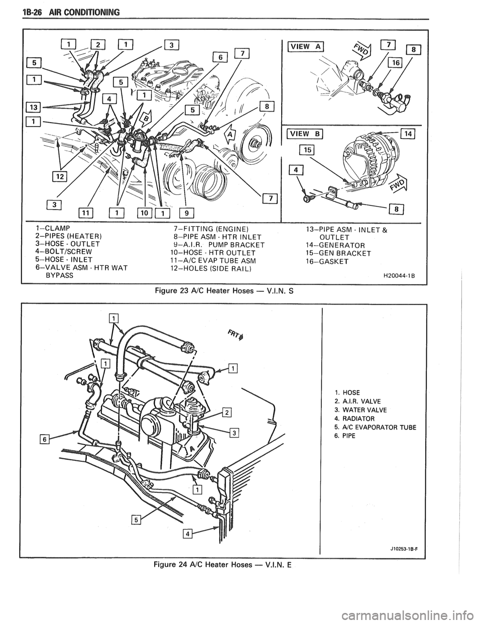
13-PIPE ASM - INLET & 8-PIPE ASM - HTR INLET
OUTLET
9-A.I.R. PUMP BRACKET 14-GENERATOR
10-HOSE
- HTR OUTLET
15-GEN BRACKET 11-AIC EVAP TUBE ASM 16-GASKET
12-HOLES (SIDE RAIL)
Figure 23 NC Heater Hoses - V.I.N. S
2. A.I.R. VALVE
3. WATER VALVE
4. RADIATOR
5. AIC EVAPORATOR TUBE
Figure 24 NC Heater Hoses - V.I.N. E
Page 70 of 1825
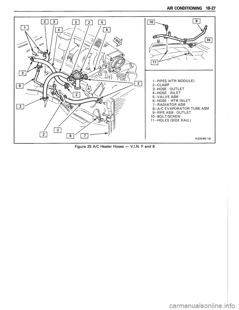
1-PIPES (HTR MODULE)
2-CLAMP
3-HOSE
- OUTLET
4-HOSE
- INLET
5-VALVE ASM
6-HOSE
- HTR INLET
7-RADIATOR ASM
8-A/C EVAPORATOR TUBE ASM
9-PIPE ASM
- OUTLET
10-BOLTISCREW
11-HOLES (SIDE RAIL)
Figure 25 A/C Heater Hoses - V.I.N. F and 8
Page 75 of 1825
1B-32 AIR CONDITIONING
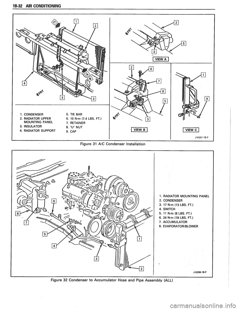
1. CONDENSER 5. TIE BAR
2. RADIATOR UPPER
6. 10 N-rn (7.4 LBS. FT.) MOUNTING PANEL 7. RETAINER
3. INSULATOR 8. "U" NUT
4. RADIATOR SUPPORT 9. CAB
I I J10257-1B-F
Figure 31 A/C Condenser Installation
1. RADIATOR MOUNTING PANEL
2. CONDENSER
3.
17 N.rn (13 LBS. FT.)
4. SWITCH
5. 11 N-rn (8 LBS. FT.)
6. 24 Nsm (18 LBS. FT.)
7. ACCUMULATOR
8. EVAPORATORIBLOWER
Figure 32 Condenser to Accumulator Hose and Pipe Assembly (ALL)
Page 109 of 1825
26-2 CHASSIS SHEET METAL
TO RAISE OR LOWER THE FRONT comers
for proper alignment, proceed as follows:
1. Close hood firmly.
2. Determine the amount of adjustment necessary.
3. Open hood.
4. Raise or lower the adjustable hood bumpers as
required.
FORE AND APT adjustment can be accom-
plished as follows:
1. Loosen hinge to fender attaching screws.
Remove or Disconnect
Open hood.
Scribe line on hood inner panel and fender panel
to indicate original hinge position.
Block hood on side where hinge is to be
removed.
Prop hood open.
Remove hinge-to-hood attaching screws and
hinge-to-fender attaching screws.
Carefully remove hinge and strut assembly.
- -
2. Reposition hinge assembly. install or Conned 3. Tighten hinge to fender attaching screws to
specifications. 1. Mount new hinge on fender using scribed line
4. If necessary, repeat procedure on opposite side for location,
and tighten attaching screws.
of hood. 2.
Position hinge to hood using scribed line for
location, install attaching screws and tighten.
3. Carefully close hood and check for proper
- - alignment.
4. If hood is misaligned, measure amount of
mis-
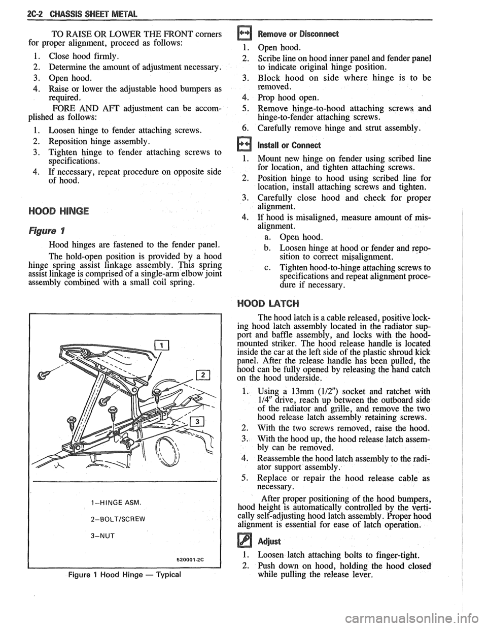
Figure 7
Hood hinges are fastened to the fender panel.
The hold-open position is provided by a hood
hinge spring assist linkage assembly. This spring
assist linkage is comprised of a
single-am elbow joint
assembly combined with a small coil spring.
1-HINGE ASM.
2-BOLT/SCREW
Figure 1 Hood Hinge - Typical
alignment.
a. Open hood.
b. Loosen hinge at hood or fender and repo-
sition to correct misalignment.
c. Tighten hood-to-hinge attaching screws to
specifications and repeat alignment proce-
dure if necessary.
HOOD L14TCI-I
The hood latch is a cable released, positive lock-
ing hood latch assembly located in the radiator sup-
port and baffle assembly, and locks with the
hood-
mounted striker. The hood release handle is located
inside the car at the left side of the plastic shroud kick
panel. After the release handle has been pulled, the
hood can be fully opened by releasing the hand catch
on the hood underside.
1. Using a
13mrn (112") socket and ratchet with
114" drive, reach up between the outboard side
of the radiator and grille, and remove the two
hood release latch assembly retaining screws.
2. With the two screws removed, raise the hood.
3. With the hood up, the hood release latch assem-
bly can be removed.
4. Reassemble the hood latch assembly to the radi-
ator support assembly.
5. Replace or repair the hood release cable as
necessary.
After proper positioning of the hood bumpers,
hood height is automatically controlled by the verti-
cally self-adjusting hood latch assembly. Proper hood
alignment is essential for ease of latch operation.
Adjust
1. Loosen latch attaching bolts to finger-tight.
2. Push down on hood, holding the hood closed
while pulling the release lever.
Page 346 of 1825
ENGINE GENERAL INFORMATION 6-1
SECTION 6
NE GENERAL NFORMAT
Description ............................................................... 6 TBI ...................................... .. ...... 6E2 ................ Engine Mechanical Multi Port Fuel Injection (MPFI) 6E3 -
............................................... 2.8L V-6 ....................................................... 6A2 Exhaust Systems 6F
5.OL V-8 ......................................................... 6A3 ~~~~~~l ~~f~~~~ti~~ ..................................... 6-2
............................ Engine Cooling ...................................................... 6B Engine Performance Diagnosis 6-3 ............................. Engine Fuel 6C Engine Mechanical Diagnosis
6-3 ........................................................... ................................... Engine Knock Diagnosis 6-4
Engine Electrical ................................................... 6D Compression Test ...................................... ... 6-5
................... Driveability and Emission Controls ...................... 6E Oil Leak Detection .. ..................... 6-5
ALL NEW GENERAL MOTORS VEHICLES ARE CERTIFIED BY THE UNITED STATES
ENVIRONMENTAL PROTECTION AGENCY AS CONFORMING TO THE REQUIREMENTS OF
THE REGULATIONS FOR THE CONTROL OF AIR POLLUTION FROM NEW MOTOR VEHICLES.
THlS CERTIFICATION IS CONTINGENT ON CERTAIN ADJUSTMENTS BEING SET TO
FACTORY STANDARDS. IN MOST CASES, THESE ADJUSTMENT POINTS EITHER HAVE
BEEN PERMANENTLY SEALED AND/OR MADE INACCESSIBLE TO PREVENT
INDISCRIMINATE OR ROUTINE ADJUSTMENT IN THE FIELD. FOR
THlS REASON, THE
FACTORY PROCEDURE FOR TEMPORARILY REMOVING PLUGS, CAPS, ETC., FOR
PURPOSES OF SERVICING THE PRODUCT MUST BE STRICTLY FOLLOWED AND,
WHEREVER PRACTICABLE, RETURNED TO THE ORIGINAL INTENT OF THE DESIGN.
DESCRIPTION OF: SECTION 6
SECTION 6A - ENGINE MECHANICAL used for each carburetor. TBI units are described in
This section general contains information on the Section 6E.
mechanical parts of the engine, such as block,
crankshaft, pistons, valve train, and camshaft, that are
common to most engines. Overhaul procedures,
removal and replacement procedures, and
s~ecifications are also covered. Subsections furnish
detailed information on each specific engine. Service
SECTION 6D - ENG l N E ELECTRICAL
information is also given that relates to that engine's
use in each
Carline. Specific subsections are: Items
covered in this section are battery,
generator, starter, primary and secondary ignition,
6A2
- 2.8L V-6 Engine
engine wire harness, spark plugs and wires, and
6A3
- 5.OL V-8 Engine
ignition switch.
SECTION 6B - ENGINE COOLING
Engine cooling system components such as
radiator, water pump, thermostat, and cooling fan, are
covered in this section. Accessory drive belts are also
covered, along with cooling system capacities.
SECTION 6C - FUEL SYSTEM
This section contains information on all the parts
of the fuel system
except the carburetor, or Throttle
Body Injection unit (TBI) itself. Items covered are fuel
tank, fuel pump, and fuel lines. Specific subsections are
SECTION 6E - DRIVEABILITY AND EMISSIONS
This section covers emission control systems
general information, and diagnostic procedures which
will lead to repairing performance and driveability
related problems for gasoline engine equipped vehicles.
All emission components are covered, as well as all
removal and replacement procedures. Instructions on
use of special tools are also given. Specific sections are:
6E
- Driveability and Emissions
6E2
- Fuel Injection (TBI)