sensor PONTIAC FIERO 1988 Service Repair Manual
[x] Cancel search | Manufacturer: PONTIAC, Model Year: 1988, Model line: FIERO, Model: PONTIAC FIERO 1988Pages: 1825, PDF Size: 99.44 MB
Page 925 of 1825
6E3-C5-4 5.OL (VIN F) & 5.7L (VIN 8) DRIVEABILITY AND EMISSIONS
CHART C-5
ELECTRONIC SPARK CONTROL
5.OL (VIN F) & 5.7L (VIN 8) ""F-ERIES (PORT)
Circuit Description:
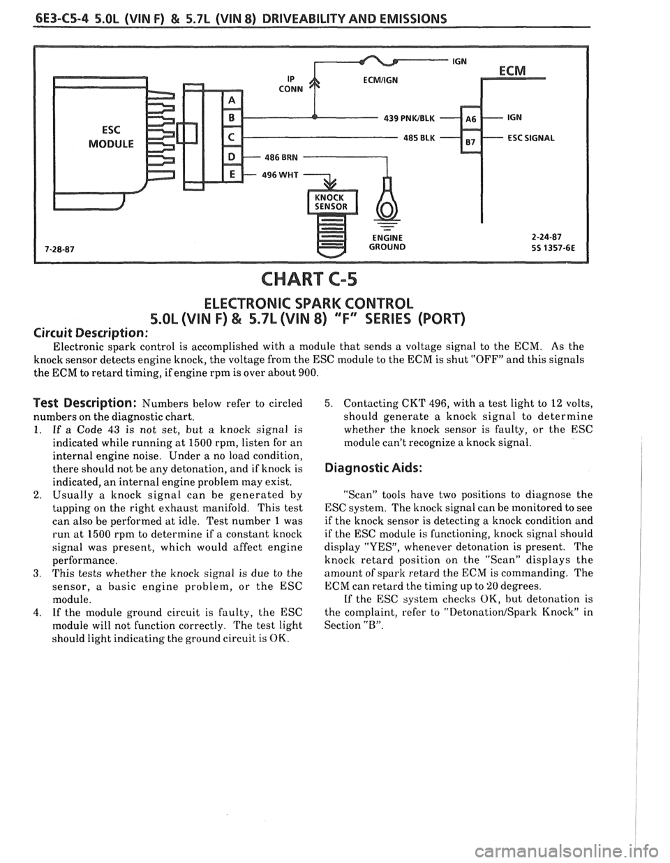
Electronic spark control is accomplished with a module that sends a voltage signal to the ECM. As the
knock sensor detects engine knock, the voltage from the
ESC module to the ECM is shut "OFF" and this signals
the ECM to retard timing, if engine rpm is over about 900.
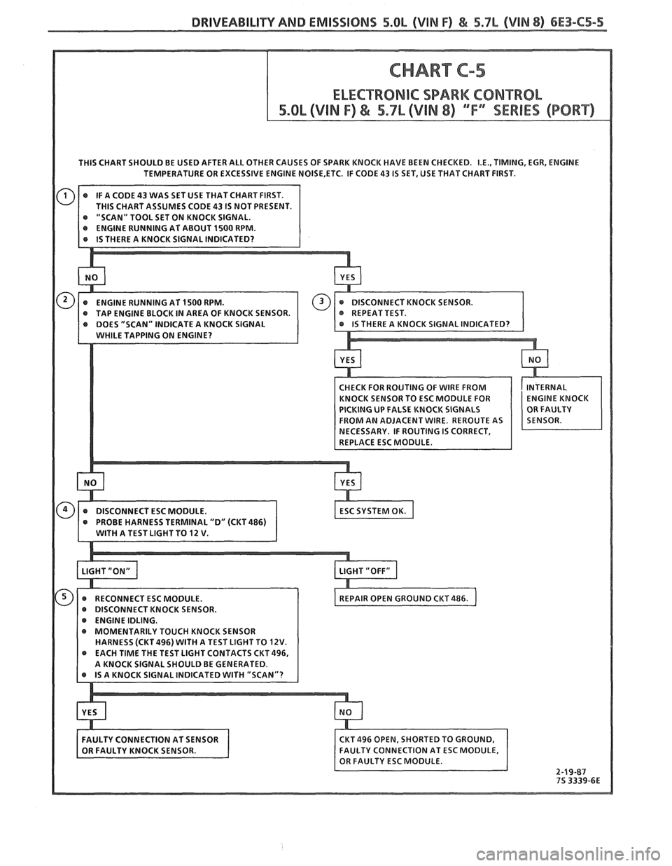
Test Description: Numbers below refer to circled
numbers on the diagnostic chart.
1.
If a Code 43 is not set, but a knock signal is
indicated while running at 1500 rpm, listen for an
internal engine noise. Under a no load condition,
there should not be any detonation, and if knock is
indicated, an internal engine problem may exist.
2. Usually a knock signal can be generated by
tapping on the right exhaust manifold. This test
can also be performed at idle. Test number
1 was
run at 1500 rpm to determine if a constant knock
signal was present, which would affect engine
performance.
3. This tests whether the knock signal is due to the
sensor,
a basic engine problem, or the ESC
module.
4. If the module ground circuit is faulty, the ESC
module will not function correctly. The test light
should light indicating the ground circuit is
OK.
5. Contacting CKT 496, with a test light to 12 volts,
should generate a knock signal to determine
whether the knock sensor is faulty, or the ESC
module can't recognize a knock signal.
Diagnostic Aids:
"Scan" tools have two positions to diagnose the
ESC system. The knock signal can be tnonitored to see
if the knock sensor is detecting a knock condition and
if the ESC module is functioning, knock signal should
display "YES", whenever detonation is present. The
knock retard position on the "Scan" displays the
amount of spark retard the ECM is commanding. The
ECM can retard the timing up to 'LO degrees.
If the ESC system checks
OK, but detonation is
the complaint, refer to
"Detonation/Spark Knock" in
Section
"B".
Page 926 of 1825
DRIVEABILITY AND EMISSIONS 5.0L (VIN F) & 5.7b (VIN 8) 6E3-C5-5
THIS CHART SHOULD BE USED AFTER ALL OTHER CAUSES OF SPARK KNOCK HAVE BEEN CHECKED. I.E., TIMING, EGR, ENGINE
TEMPERATURE OR EXCESSIVE ENGINE
NOISE,ETC. IF CODE 43 IS SET, USE THAT CHART FIRST.
@ "SCAN" TOOL SET ON KNOCK SIGNAL.
@ RECONNECT ESC MODULE.
DISCONNECT KNOCK SENSOR.
@ ENGINE IDLING.
MOMENTARILY TOUCH KNOCK SENSOR
HARNESS (CKT
496) WITH A TEST LIGHT TO 12V.
Page 928 of 1825
DRIVEABILITY AND EMISSIONS 5.OL (VIN F) & 5.7L (VIN 8) 6E3-C6-1
SECTION C6
AIR INJECTION REACTION (A.I.R.) SYSEEM
CONTENTS
GENERAL DESCRIPTION ............... C6-1
PURPOSE ....................... C6-1
OPERATION. ..................... C6-1
AIR CONTROL PEDES VALVE ......... C6-1
.... RESULTS OF INCORRECT OPERATION C6-2
DIAGNOSIS
........................ C6-2
OPERATIONAL CHECKS ............. C6-2
Air Pump ...................... C6-2
Hoses and Pipes ................. C6-3
GENERAL DESCRIPTION
PURPOSE
The A.I.R. system helps reduce hydrocarbon (HC),
carbon monoxide (CO), and oxides of nitrogen (NO,)
exhaust emissions. It also heats up the catalytic
converter quickly on engine start-up so conversion of
exhaust gases can occur sooner.
A dual bed converter is used. It consists of a three
way catalyst (which controls all three emissions) in
series with
a two way catalyst (which controls only HC
and
CO) both are in one housing. A pipe between the
two converters allows air to be injected into the second
(two way) converter to increase its efficiency to further
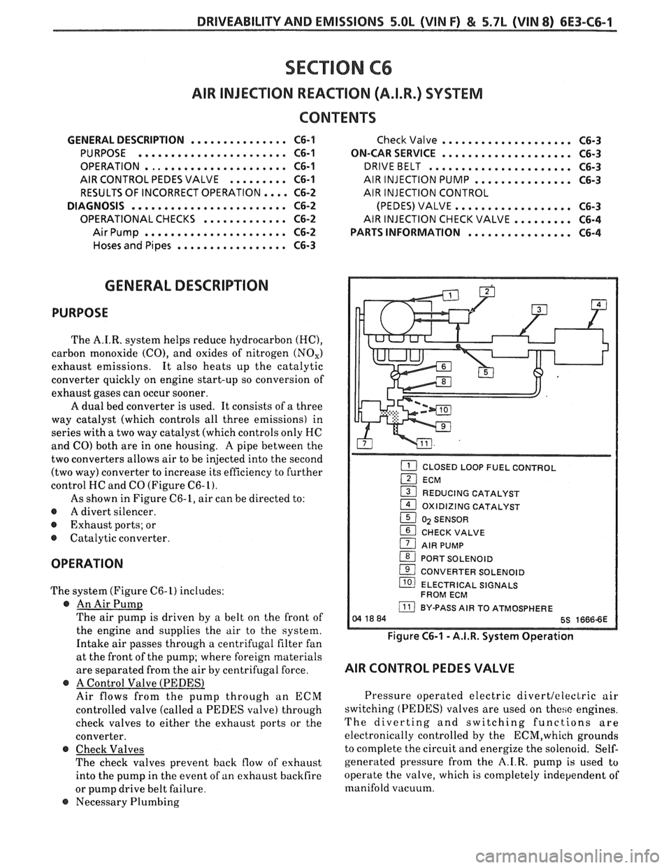
control HC and CO (Figure
C6-L).
As shown in Figure C6-1, air can be directed to:
@ A divert silencer.
@ Exhaust ports; or
@ Catalytic converter.
OPERATION
The system (Figure C6-1) includes:
@ An Air Pump
The air pump is driven by a belt on the front of
the engine and supplies the air to the system.
Intake air passes through a centrifugal filter fan
at the front of the pump; where foreign materials
are separated from the air by centrifugal force.
@ A Control Valve (PEDESl
Air flows from the pump through an ECM
controlled valve (called a PEDES valve) through
check valves to either the exhaust ports or the
converter.
@ Check Valves
The check valves prevent back flow of exhaust
into the pump in the event of
an exhaust backfire
or pump drive belt failure.
@ Necessary Plumbing
Check Valve .................... C6-3
ON-CAR SERVICE
.................... C6-3
DRIVEBELT ...................... C6-3
AIR INJECTION PUMP ............... C6-3
AIR INJECTION CONTROL
(PEDES) VALVE..
................ C6-3
AIRINJECTIONCHECKVALVE.. ....... C6-4
PARTS INFORMATION
................ C6-4
CLOSED LOOP FUEL CONTROL I
(2I ECM
1 REDUCING CATALYST
1 OXIDIZING CATALYST
1 0) SENSOR
1 CHECK VALVE
1 AIR PUMP
(BI PORT SOLENOID
( CONVERTER SOLENOID
llO) ELECTRICAL SIGNALS
FROM ECM
j BY-PASS AIR TO ATMOSPHERE
Figure C6-1 - A.I.R. System Operation
AIR CONTROL PEDES VALVE
Pressure operated electric divertleleclric air
switching (PEDES) valves are used on
these engines.
The diverting and switching functions are
electronically controlled by the
ECM,which grounds
to complete the circuit and energize the solenoid. Self-
generated pressure from the A.I.R. pump
is used to
operate the valve, which is completely independent of
manifold vacuum.
Page 939 of 1825
6E3-C7-4 5.OL (VIN F) €4 5.7L (VIN 8) DRIVEABILITY AND EMISSIONS
CHART C-7
EXHAUST GAS RECIRCULATION CHECK
5.OL (VIN F) & 5.7L (VIN 8) "F" SERIES (PORT)
Circuit Description:
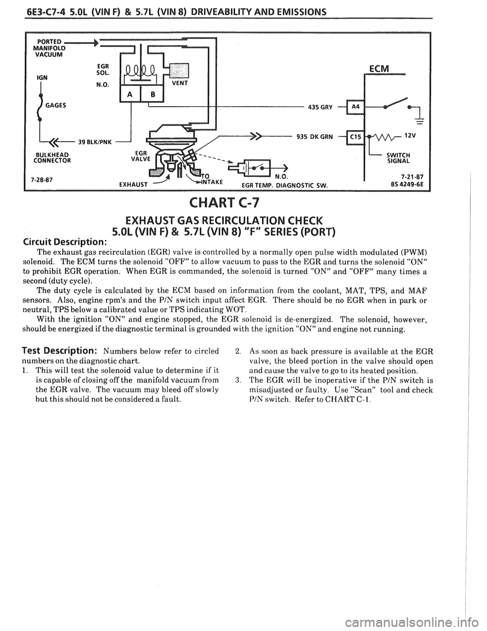
The exhaust gas recirculation (EGR) valve is controlled by a normally open pulse width modulated (PWM)
solenoid. The ECM turns the solenoid "OFF" to allow vacuum to pass to the EGR and turns the solenoid "ON"
to prohibit EGR operation. When EGR is commanded, the solenoid is turned "ON" and "OFF" many times a
second (duty cycle).
The duty cycle is calculated by the ECM based on information from the coolant, MAT, TPS, and MAF
sensors. Also, engine
rpm's and the PIN switch input affect EGR.
There should be no EGR when in park or
neutral, TPS below
a calibrated value or TPS indicating WOT.
With the ignition "ON" and engine stopped, the EGR solenoid is de-energized. The solenoid, however,
should be energized if the diagnostic terminal is grounded with the ignition "ON" and engine not running.
Test Description: Numbers below refer to circled 2. As soon as back pressure is available at the EGR
numbers on the diagnostic chart.
valve, the bleed portion in the valve should open
1. This will test the solenoid value to determine if it
and cause the valve to go to its heated position.
is capable of closing off the manifold vacuum from
3. 'I'he EGR will be inoperative if the PIN switch is
the EGR valve. The vacuum may bleed off slowly
misadjusted or faulty. Use "Scan" tool and check
but this should not be considered a fault.
PIN switch. Refer to CHART C-1.
Page 942 of 1825
DWlVEABlLlTV AND EMISSIONS 5.01, QVIN F) & 5.71 (VIN 8) 6E3-C8-1
TRANSMISSION CONVERTER CLUTCH (KC) SYSTEM
AND MANUAL "TRANSMISSION SHlFT LBGH"O"=Ob ONLY
CONTENTS
................ GENERAL DESCRIPTION C8-1 DIAGNOSIS ....................... .. C8-1
........ PURPOSE ......................... CS-1 SHIFT LIGHT (MIT) DESCRIPTION C8-1
....................... OPERATION C8-1 DIAGNOSIS ......................... CS-1
OM-CAR SERVICE ..................... C8-1
GENERAL DESCRIPTION
PURPOSE
The transmission converter clutch (TCC) system
uses
a solenoid operated valve in the automatic
transmission to couple the engine flywheel to the
output shaft of the transmission thru the torque
converter. This reduces the slippage losses in the
converter, which increases fuel economy.
OPERATION
For the converter clutch to apply, two conditions
must be met:
e Internal transmission fluid pressure must be
correct. For information on internal transmission
operation, see Section
"7A". This section will
cover only the electrical operation of the TCC
system.
@ The ECM grounds a switch internally to turn
"ON" a solenoid in the transmission. This moves a
check ball, which will allow the converter clutch
to apply, if the hydraulic pressure is correct, as
described above.
The ECM controls the TCC apply solenoid by
looking at several sensors:
@ Speedo Buffer Sensor (also called Vehicle Speed
Sensor
(VSS) Speed must be above a certain value
before the clutch can apply.
@ Coolant Temperature Sensor Engine must be
warmed
LIP before clutch can apply about 65" C
(149°F).
Throttle Position Sensor (TPS) After the
converter clutch applies, the ECM uses the
information
from the TPS to release the clutch
when the car is accelerating or decelerating at
a
certain rate.
The brake switch
is also part of the 'I'CC circuit as
it will remove battery voltage to the
'FCC solenoid
when the brake pedal is depressed.
@ Gear Select Switch The 4th gear switch is used to
send a signal to the ECM telling it when the
transmission is in 4th
gear
The ECM uses this information to vary the conditions
under which the clutch applies or releases. However,
the transmission does not have to be in fourth gear in
order for the ECM to turn the clutch "ON".
If the converter clutch is applied at all times, the
engine will stall immediately, just as in a manual
transmission with the clutch applied.
If the converter
clutch does not apply, fuel
ecomony may be lower than expected. If the vehicle
speed sensor fails, the TCC will not apply. If the 4th
gear switch does not operate, the TCC may not apply
at the right time.
DIAGNOSIS
The diagnosis of the TCC system is covered in
CHART C-$A. If the ECM detects a problem in the
system, a Code 24 should set. In this case, see Code 24
CHART.
SHIFT LIGHT (MR) DESCRIPTION
The purpose of the shift light is to provide a
display which indicates the optimum fuel economy
point for up shifting the manual transmission based
on engine speed and load. The display is
a lamp on the
instrument panel. Activation
of the ECM driver turns
the lamp "ON".
DIAGNOSIS
The shift light circuit can be checked using
CEIAR'I' C-8B.
ON-CAR SERVICE
See Section "8B" if the shift light bulb needs
replacement.
See Section
"GE" to repair wiring problem.
@ See Section "C- 1" if ECM is to be replaced.
Page 950 of 1825
DRlVEABlLlPV AND EMISSIONS 5.OL (VIN F) & 5.7L (VIN 8) 6E3-C"1-1
SECTION Cl2
COOLING FAN CONTROL
CONTENTS
GENERAL DESCRIPTION ................ C12-I DIAGNOSIS ......................... C1Z-1
OPERATION ..................... .. C12-1 ON-CARSERVICE ..................... C12-1
PARTS INFORMATION ................. C12-1
GENERAL DESCRIPIION DlAGNODlS
The fan is used for engine and AIC condenser
cooling but the fan only operates under certain
conditions. The
following charts will diagnose the ECM
controlled cooling fan.
Use
Sect.ion "8A" to diagnose the secondary
cooling fan.
OPERATION
ON-CAR SERVICE
The electric cooling fan on this engine is controlled
by the ECM. The ECM will ground the cooling fan
relay, which turns "ON" the fan, when the following
conditions are met.
@ Coolant temperature sensor signal indicating a
temperature greater than 106°C
(222°F).
@ AIC head pressure greater than 233 psi and
vehicle speed less than 40 mph.
When the cooling fan is turned "ON", it will stay
"ON" for a minimum time of 15 seconds. Cooling
system component replacement can be
found in Section
"6B".
PARTS INFORMATION
PART NAME GROUP
......................... Fan, Engine 1.055
......................... Motor, Fan. 1.055
.................... Relay, Engine Fan 1.055
Page 951 of 1825
6E3-C12-2 5.OL (VIN F) & 5.7b (VIN 8) DRIVEABILITY AND EMISSIONS
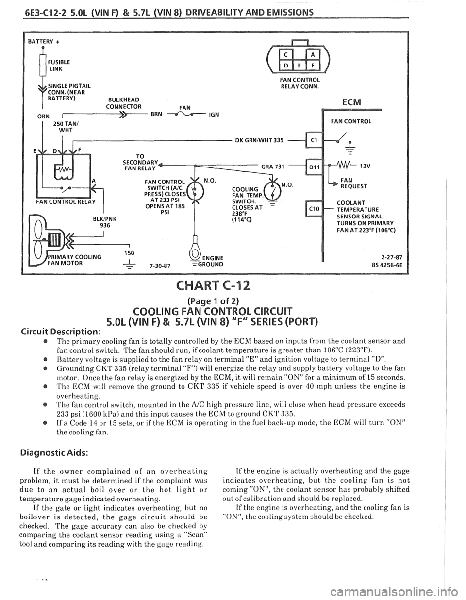
FAN CONTROL
RELAY CONN.
DK GRNNVHT 335
TEMPERATURE
SENSOR SIGNAL.
TURNS ON PRIMARY
FAN AT
223OF (1 06'C)
CHART C-12
(Page 1 of 2)
COOLING FAN CONTROL CIRCUIT
5.8L (VIN F) & 5.7L (VIN 8) "F" SSERlES (PORT)
Circuit Description:
The primary cooling fan is totally controlled by the ECM based on inputs from the coolant sensor and
fan control switch. The fan should run, if coolant temperature is greater than 106°C
(223°F).
@ Battery voltage is supplied to the fan relay on terminal "En and ignition voltage to terminal "D".
@ Grounding CKT 335 (relay terminal "F") will energize the relay and supply battery voltage to the fan
motor. Once the fan relay is energized by the
ECM, it will remain "ON" for a minimum of 15 seconds.
@ 'I'he ECM will remove the ground to CKT 335 if vehicle speed is over 40 rnph unless the engine is
overheating.
@ 'I'he fan control switch, mounted in Lhe AIC high pressure line, will close when head pressure exceeds
233 psi (1600 kPa) and this input causes the ECM to ground CKT 335.
@ If a Code 14 or 15 sets, or if the ECM is operating in the fuel back-up mode, the ECM will turn "ON"
the cooling fan.
Diagnostic Aids:
If the owner complained of an overheating If
the engine is actually overheating and the gage
problem, it must be determined if the complaint was indicates
overheating, but
t,he cooling fan is not
due to an actual boil over or the hot light or coming
"ON", the
coolant sensor has probably shifted
temperature gage indicated overheating. out
of calibration and should be replaced.
If the gate or light indicates overheating, but no If
the engine is overheating, and the cooling fan is
boilover is detected, the gage circuit should be "ON", the cooling system should be checked.
checked. The gage accuracy can also be checked by
comparing the coolant sensor reading using
a "Scan.'
tool and comparing its reading with the gage reading.
Page 953 of 1825
6E3-C12-4 5.8L (VIN F) & 5.7L (VIN 8) DRIVEABILITY AND EMISSIONS
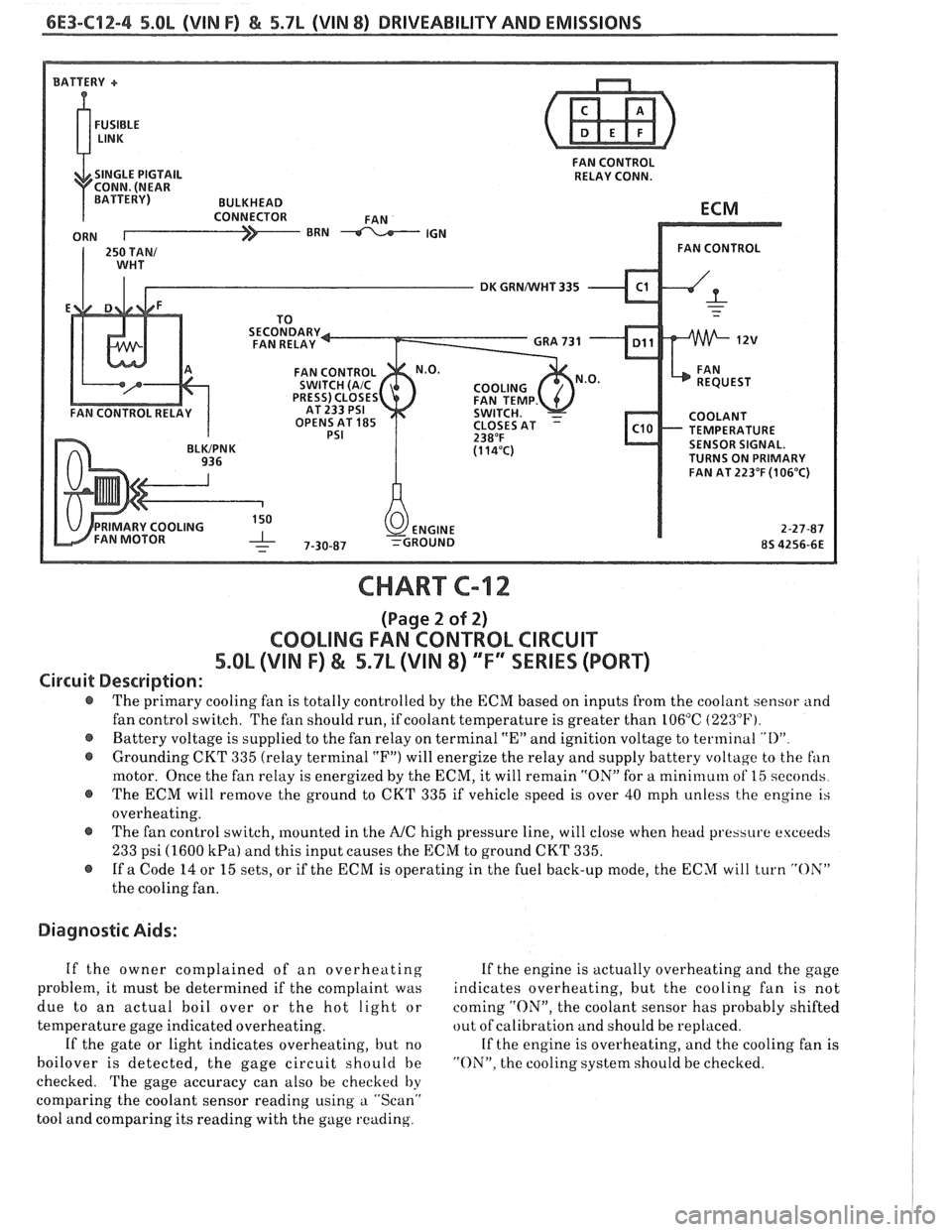
FAN CONTROL
SINGLE PIGTAIL RELAY CONN.
DK GRNNVHT 335
OPENS AT
185 TEMPERATURE SENSOR SIGNAL.
TURNS ON PRIMARY
FAN AT 223°F
(106°C)
CHART C-12
(Page 2 of 2)
COOLING FAN CONTROL CIRCUIT
5.OL (VIN F) & 5.7L (VIN 8) ""FYSERlES (PORT)
Circuit Description:
@ The primary cooling fan is totally controlled by the ECM based on inputs from the coolant sensor and
fan control switch. The fan should run, if coolant temperature is greater than 106°C
(223°F).
@ Battery voltage is supplied to the fan relay on terminal "En and ignition voltage to terminal "I)"
@ Grounding CKT 335 (relay terminal "F") will energize the relay and supply battery voltage to the fan
motor. Once the fan relay is energized by the ECM, it will remain "ON" for a mini~nuln of 15 seconds
@ The ECM will remove the ground to CKT 335 if vehicle speed is over 40 mph unless the engine is
overheating.
@ The fan control switch, mounted in the A/C high pressure line, will close when head pressure exceeds
233 psi (1600 kPa) and this input causes the ECM to ground CKT 335.
@ If a Code 14 or 15 sets, or if the ECM is operating in the fuel back-up mode, the ECM will turn "OX"
the cooling fan.
Diagnostic Aids:
If the owner complained of an overheating If the engine is actually overheating and the gage
problem, it must be determined if the complaint was indicates overheating, but the cooling fan is not
due to an actual boil over or the hot light or coming
"ON", the coolant sensor has probably shifted
temperature gage indicated overheating. out
of calibration and should be replaced.
If the gate or light indicates overheating, but no If the engine is overheating, and the cooling fan is
boilover is detected, the gage circuit should be "ON". the cooling system should be checked.
checked. The gage accuracy can also be checked
by
comparing the coolant sensor reading using a "Scan"
tool and comparing its reading with the gage reading.
Page 958 of 1825
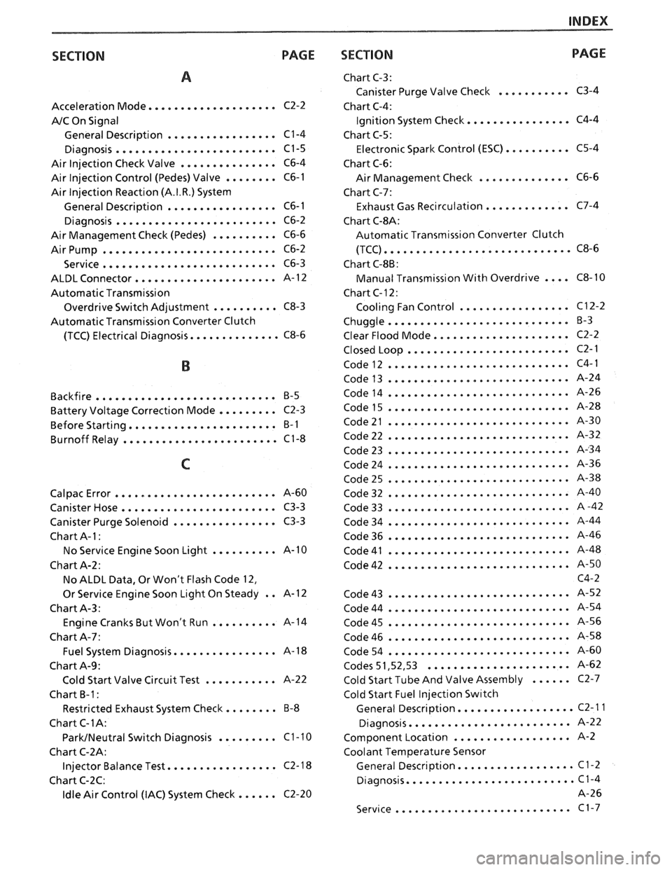
INDEX
SECTION PAGE
.................... Acceleration Mode C2-2
A/C On Signal
General Description
................. C1-4
......................... Diagnosis C1-5
Air Injection Check Valve
............... C6-4
Air Injection Control (Pedes) Valve
........ C6-1
Air Injection Reaction (A.I.R.) System
General Description
................. C6-1
......................... Diagnosis C6-2
Air Management Check (Pedes)
.......... C6-6
AirPump ........................... C6-2
........................... Service C6-3
...................... ALDL Connector A- 12
Automatic Transmission
Overdrive Switch Adjustment
.......... C8-3
Automatic Transmission Converter Clutch
(TCC) Electrical Diagnosis
.............. C8-6
Backfire
............................ B-5
Battery Voltage Correction Mode
......... C2-3
....................... Before Starting B-I
........................ Burnoff Relay C1-8
......................... Calpac Error 8-60
........................ Canister Hose C3-3
Canister Purge Solenoid
................ C3-3
Chart
A-1 :
.......... No Service Engine Soon Light A-1
0
Chart
A-2:
No ALDL Data. Or Won't Flash Code 12.
Or Service Engine Soon Light On Steady
. . A-1 2
Chart A-3:
Engine Cranks But Won't Run
.......... A-14
Chart A-7:
................ Fuel System Diagnosis A- 18
Chart A-9:
........... Cold Start Valve Circuit Test A-22
Chart
B-1:
Restricted Exhaust System Check ........ B-8
Chart
C-1A:
......... ParkINeutral Switch Diagnosis C1-10
Chart C-2A:
................. Injector Balance Test C2-18
Chart C-2C:
Idle Air Control (IAC) System Check ...... C2-20
SECTION PACE
Chart C-3:
........... Canister Purge Valve Check C3-4
Chart C-4:
................ Ignition System Check C4-4
Chart
6-5:
.......... Electronic Spark Control (ESC) C5-4
Chart C-6:
.............. Air Management Check C6-6
Chart C-7:
Exhaust Gas Recirculation
............. C7-4
Chart
C-8A:
Automatic Transmission Converter Clutch
............................. (TCC) C8-6
Chart C-8B:
Manual Transmission With Overdrive
.... C8-10
Chart C- 12
:
................. Cooling Fan Control C12-2
............................ Chuggle B-3
................... Clear Flood Mode.. C2-2
......................... Closed Loop C2-1
Code12
............................ C4-1
Code13
............................ A-24
Code14
............................ A-26
Code15
............................ A-28
Code21
............................ A-30
Code22
............................ A-32
Code23
............................ A-34
Code24
............................ A-36
Code25
............................ A-38
Code32
............................ A-40
Code33
............................ A-42
Code34
............................ A-44
Code36
............................ A-46
Code41
............................ A-48
Code42
............................ A-50 C4-2
Code43
............................ A-52
Code44
............................ A-54
Code45
............................ A-56
Code46
............................ A-58
Code54
............................ A-60
...................... Codes 51.52. 53 A-62
Cold Start Tube And Valve Assembly
...... C2-7
Cold Start Fuel
lnjection Sw~tch
.................. General Description C2-11
......................... Diagnosis A-22
.................. Component Location A-2
Coolant Temperature Sensor
.................. General Description C1-2
.......................... Diagnosis C1-4
A-26
........................... Service C1-7
Page 959 of 1825
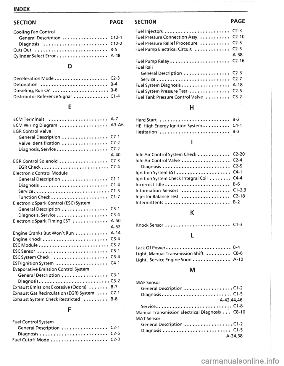
INDEX
SECTION PAGE
Cooling Fan Control
................. General Description C12-1
........................ Diagnosis C12-2
........................... Cuts Out B-5
................... Cylinder Select Error A-48
.................... Deceleration Mode C2-3
......................... Detonation B-4
..................... Dieseling. Run On B-6
............. Distributor Reference Signal C1-4
...................... ECM Terminals A-7
.................. ECM Wiring Diagram A3-A6
EGR Control Valve
................. General Description C7-1
................. Valve Identification C7-2
................... Diagnosis. Service C7-2
A-40
.................. EGR Control Solenoid C7-3
......................... EGR Check C7-4
Electronic Control Module
................. General Description C1-1
......................... Diagnosis C1-4
............................ Service C1-5
..................... Function Check C1-7
Electronic Spark Control (ESC) System
................. General Description C5-1
................... Diagnosis. Service C5-4
Electronic Spark Timing EST
............. A-50
A-52
Engine Cranks But Won't Run
............ A-14
........................ Engine Knock C5-4
.......................... ESC Module C5-2
.......................... ESC Sensor C5-1
.................... ESC System Check C5-4
................... ESTllgnition System C4-1
Evaporative Emission Control System
................. General Description C3-1
.......................... Diagnosis C3-2
Exhaust Emissions Excessive (Odors)
....... B-7
Exhaust Gas Recirculation (EGR) System
.... C7-1
Exhaust System Check Restricted
......... B-8
Fuel Control System
................. General Description C2- 1
......................... Diagnosis C2-5
..................... Fuel Cutoff Mode C2-3
SECTION PAGE
Fuel Injectors ........................
Fuel Pressure Connection Assy ............
Fuel Pressure Relief Procedure ...........
Fuel Pump Electrical Circuit .............
Fuel Pump Relay ......................
Fuel Rail
General Description
.................
........................... Service
Fuel System Diagnosis
..................
Fuel System Pressure Test ...............
Fuel Tank Pressure Control Valve .........
.......................... Hard Start B-2
.......... HE1 High Energy Ignition System C4-1
.......................... Hesitation
B-3
............ Idle Air Control System Check C2-20
.................. Idle Air
Control Valve C2-4
......................... Diagnosis C2-5
.................... Ignition System EST C4-1
........ Ignition System Check Integral Coil C4-4
........................ Incorrect Idle B-6
.................. Information Sensors C1.2. 9
.................. Injector
Balance Test C2-18
........................ lntermittents B-2
........................ Knock Sensor C1-3
........................ Lack Of Power B-4
......... Light. Manual Transmission Shift C8-6
.............. Light. Service Engine Soon A-10
MAF Sensor
.................. General Description C1-2
.......................... Diagnosis C1-5
A.42.44. 46
............................ Service C1-8
... Manual Transmission Electrical Diagnosis C8-10
MAT Sensor
.................. General Description C1-2
......................... Diagnosis C1-5
A.34. 38