sensor PONTIAC FIERO 1988 Service Repair Manual
[x] Cancel search | Manufacturer: PONTIAC, Model Year: 1988, Model line: FIERO, Model: PONTIAC FIERO 1988Pages: 1825, PDF Size: 99.44 MB
Page 975 of 1825
6E-14 DRIVEABILITY AND EMISSIONS - FUEL INJECTION
N.O. - NORMALLY OPEN - State of relay contacts
or solenoid plunger when no voltage
is applied.
NOx - NITROGEN, OXIDES OF - One of the
pollutants found in engine exhaust.
O2 - OXYGEN (Sensor) - Monitors the oxygen
content of the exhaust system and generates a voltage
signal to the ECM.
OIL or OILOOP - OPEN LOOP - Describes ECM fuel
control without use of oxygen sensor information.
OUTPUT - Result of a function typically controlled
by the ECM.
OXYGEN SENSOR. EXHAUST - Device that detects
the amount of oxygen
(02) in the exhaust stream.
P.A.1.R - PULSE AIR INJECTION REACTOR system -
pulsed air directed into engine to reduce exhaust
emissions.
PCV - POSITIVE CRANKCASE VENTILATION -
Prevent fumes in crankcase from passing into
atmosphere.
PFI - PORT FUEL INJECTION
PIN
- PARWNEUTWL
PORT - EXHAUST OR INTAKE PORT
PROM
- PROGRAMABLE READ ONLY MEMORY-
an electronic term used to describe the engine
calibration unit
.
RPM - REVOLUTIONS PER MINUTE - A measure of
rotational speed.
RVB - REAR VACUUM BMKE - is used to control
choke operation during cold engine conditions.
SELF-DIAGNOSTIC CODE - The ECM can detect
malfunctions in the system.
If a malfunction occurs,
the ECM turns on the "Service Engine Soon" light.
A
diagnostic code can be obtained from the ECM
through the "Service Engine Soon" light, or by use of a
"Scan" tool. This code will indicate the area of the
malfunction.
SES - SERVICE ENGINE SOON LIGHT - Lights when
a malfunction occurs in Computer Command Control
system.
TACH - TACHOMETER
TBI
- THROTTLE BODY INJECTION (Unit) - is
controlled by the ECM to supply precise airlfuel
mixture into the intake manifold.
TCC - TWNSMISSION I TRANSAXLE CONVERTER
CLUTCH
- ECM controlled solenoid in transmission
which positively couples the transmission to the
engine.
THERMAC - THERMOSTATIC AIR CLEANER -
provides preheated air to intake manifold to provide
better driveability when engine
is cold.
TPS - THROnLE POSITION SENSOR - Device that
tells the ECM the throttle position.
TVS - THERMAL VACUUM SWITCH - Used to
control vacuum in relationship to engine temperature.
V - VOLT
V-6 - SIX CYLINDER ENGINE - Two banks of
cylinders, arranged in a
"V".
V-8 - EIGHT CYLINDER ENGINE - Two banks of
cylinders, arranged in a
"V".
VACUUM - Negative pressure; less than
atmospheric pressure.
VACUUM, MANIFOLD - Vacuum source in
manifold below throttle plate.
VACUUM, PORTED - A vacuum source above I (atmospheric side ) of closed throttle plate. , I
WAC SENSOR - Abbreviation for differential
pressure sensor which is a
vacuum sensor.
VIN - VEHICLE IDENTIFIUTION NUMBER. 1
VSS - VEHICLE SPEED SENSOR - Sensor which
sends vehicle speed information to the ECM.
WASTECATE - A means of controlling the amount
of boost available for a Turbo charged engine.
WOT- WIDE OPEN THROPTLE. I
WIRING HARNESS SERVICE I
The ECM wire harness electrically connects the
ECM to the various solenoids, switches, and sensors in
vehicle engine compartment. The ECM is located
inside the vehicle passenger compartment.
Most connectors in the engine compartment are
protected against moisture and dirt which could create
oxidation and deposits on the terminals. This
protection is important because of the very low voltage
and current levels found in the electronic system. The
connectors have a lock which secures the male and
female terminals together. A secondary lock holds the
seal and terminal into the connector.
GENERAL
Molded-on connectors (like Metri-Pack) require
complete replacement of the connector. This means
splicing a new connector assembly into the harness.
Page 976 of 1825
DRIVEABILITY AND EMISSIONS - FUEL INJECIION 6E-15
1. REMOVE OUTER JACKET. 2. UNWRAP ALUMINYM/MYbAR TAPE. DO NOT
REMOVE MYLAR. 4. LOCATE DAMAGED WIRE. 2. REMOVE INSULATION ASBEOUIRED.
3. UNTWIST CONDUCTORS. STRIP INSULATION AS 3. SPLICE TWO WIRES TOGETHER USING SPLICE
NECESSARY. CLIPS AND ROSIN CORE SOLDER.
4. COVER SPLICE WlTH TAPE TO INSULATE
FROM OTHER WIRES.
5. RETWIST AS BEFORE AND TAPE WITH ELECTRICAL TAPE AND HOLD IN PLACE.
6. TAPE OVER WHOLE BUNDLE TO SECURE AS BEFORE.
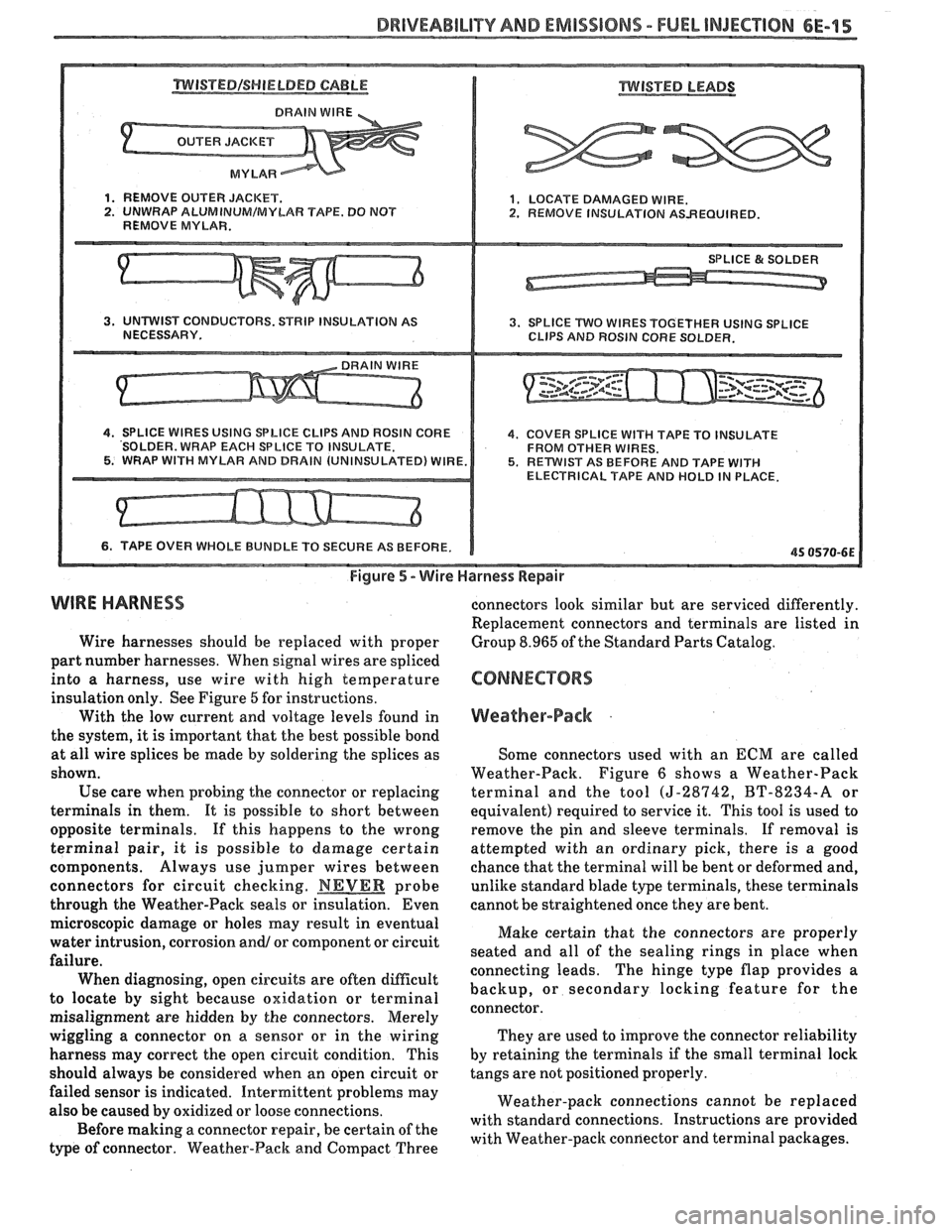
Figure 5 - Wire Harness Repair
WIRE HARNESS
Wire harnesses should be replaced with proper
part number harnesses. When signal wires are spliced
into a harness, use wire with high temperature
insulation only. See Figure
6 for instructions.
With the low current and voltage levels found in
the system, it
is important that the best possible bond
at all wire splices be
made by soldering the splices as
shown.
Use care when probing the connector or replacing
terminals in them. It is possible to short between
opposite terminals. If this happens to the wrong
terminal pair, it is possible
to damage certain
components. Always use jumper wires between
connectors for circuit checking.
NEVER probe
through the Weather-Pack seals or insulation. Even connectors
look similar but are serviced differently.
Replacement connectors and terminals are listed in
Group 8.965 of the Standard Parts Catalog.
Weather-Pack .
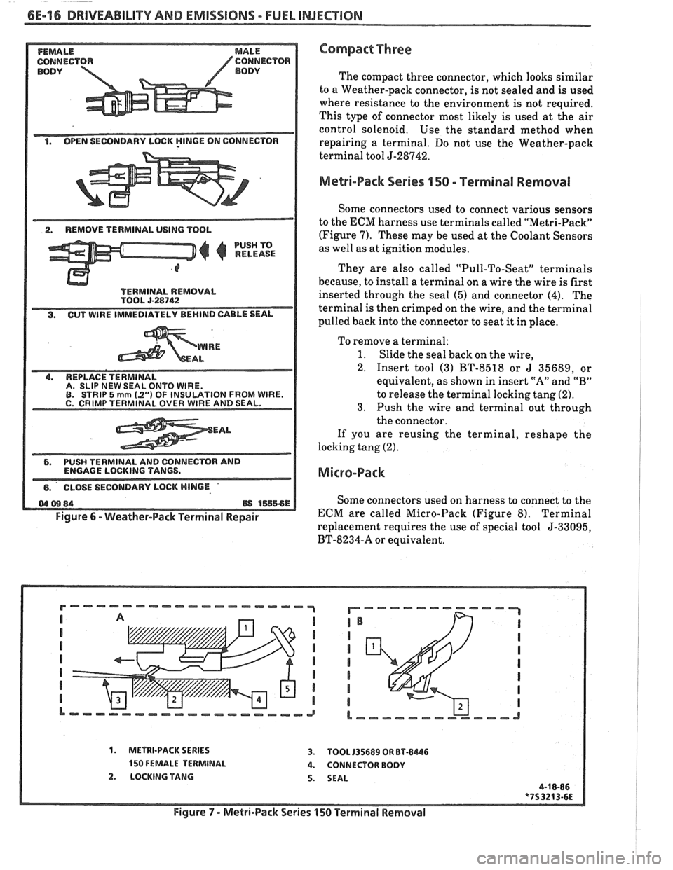
Some connectors used with an ECM are called
Weather-Pack. Figure
6 shows a Weather-Pack
terminal and the tool
(5-28942, BT-8234-A or
equivalent) required to service it. This tool is used to
remove the pin and sleeve terminals. If removal is
attempted with an ordinary pick, there is a good
chance that the terminal will be bent or deformed and,
unlike standard blade type terminals, these terminals
cannot be straightened once they are bent.
microscopic damage or holes may result in eventual
Make certain that the connectors are properly
water intrusion,
corr~sion an& or component or circuit
seated and all of the sealing rings in place when
failure. connecting leads. The hinge type flap provides a
When diagnosing, open circuits are often
difficult backup, or secondary locking feature for the
to locate by sight because oxidation or terminal
connector.
misalignment are hidden by the connectors. Merely
wiggling a connector on a sensor or in the wiring They
are used to improve the connector reliability
harness may correct the open circuit condition. This by
retaining the terminals
if the small terminal lock
should always be considered when an open circuit or tangs are not
positioned properly.
failed sensor is indicated. Intermittent problems may
Weather-pack connections cannot be replaced
also be caused by oxidized or loose connections.
with standard connections. Instructions are provided
Before making a connector repair, be certain of the
with Weather-pack connector and terminal packages.
type
of connector. Weather-Pack and Compact Three
Page 977 of 1825
6E-16 DRIVEABILIW AND EMISSIONS - FUEL INJECTION
BODY BODY
1. OPEN SECONDARY LBCK YlNGE ON CONNECTOR
2. REMOVE TERMINAL USING TOOL
PUSH TO
RELEASE
A. SLIP NEW SEAL ONTO WIRE.
EAL
6. PUSH TERMINAL AND CONNECTOR AND
ENGAGE LOCKING TANGS.
Figure
6 - Weather-Pack Terminal Repair
Compact Three
The compact three connector, which looks similar
to a Weather-pack connector, is not sealed and is used
where resistance to the environment is not required.
This type of connector most likely is used at the air
control solenoid, Use the standard method when
repairing a terminal. Do not use the Weather-pack
terminal tool J-28742,
Melri-Pack Series 150 - Terminal Removal
Some connectors used to connect various sensors
to the ECM harness use terminals called "Metri-Pack"
(Figure 7). These may be used at the Coolant Sensors
as well as at ignition modules.
They are also called "Pull-To-Seat" terminals
because, to install a terminal on a wire the wire is first
inserted through the seal (5) and, connector
(4). The
terminal is then crimped on the wire, and the terminal
pulled back into the connector to seat it in place.
To remove a terminal:
1. Slide the seal back on the wire,
2. Insert tool (3) BT-8518 or
J 35689, or
equivalent, as shown in insert "A" and "B"
to release the terminal locking tang (2).
3. Push the wire and terminal out through
the connector.
If you are reusing the terminal, reshape the
locking tang (2).
Micro-Pack
Some connectors used on harness to connect to the
ECM are called Micro-Pack (Figure 8). Terminal
replacement requires the use of special tool
5-33095,
BT-8234-A or equivalent.
1. METRI-PACK SERIES 3. TOOL 135689 OR BT-8446
150 FEMALE TERMINAL 4. CONNECTOR BODY
2. LOCKING TANG 5. SEAL
Figure
7 - Metri-Pack Series 150 Terrninal Removal
Page 980 of 1825
DRIVEABILITY AND EMISSIONS - FUEL INJECTION 6E-19
OXYGEN SENSOR WRENCH
Used to remove or install the oxygen sensor.
IDLE AIR CONTROL WRENCH
Used to remove or install IAC valve on throttle body.
PORT FUEL INJECTION DIAGNOSTIC KIT
Used to diagnose poPt fuel injection systems.
The kit includes:
@ Fuel Pressure Gage -to check fuel pump pressure
and compare injector pressure drop for equal fuel
distribution. lnjector Test Light -to check electrical circuit to an
injeclor.
@ Injector Tester - to energize each fuel injector for a
precise amount of time to perform injector balance
test in
CHART C-2A by checking each injector's
pressure drop using pressure gage.
FUEL PRESSURE GAGE
Used to check and monitor fuel line pressure of port
fuel system.
Part of Diagnostic Kit 134730-A
INJECTOR TEST LIGHT
Used to check electrical circuit to a port fuel injector
Pae of Diagnostic Kit 134730-A
INJECTOR TEST LIGHT
Used to check eledrical circuit to a TBI fuel injector
(except
TBI 700)
INJECTOR TEST LIGHT
Used to check electrical circuit to a TBI 700 fuel
injector and a port fuel injector.
5-2-86
75 3396-6E
Page 981 of 1825
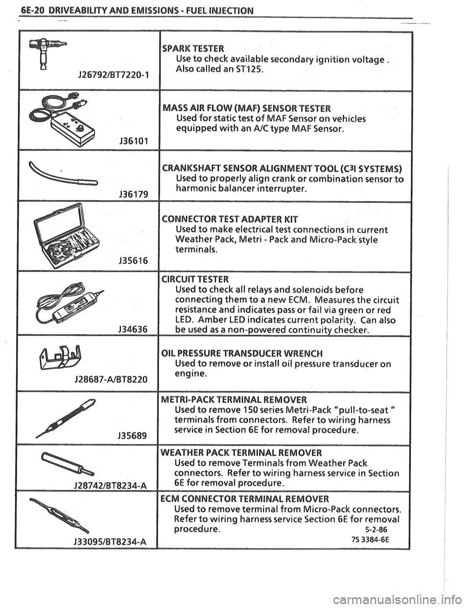
6E-20 DRIVEABILITY AND EMISSIONS - FUEL INJECnION -
SPARK TESTER
Use to check available secondary ignition voltage .
Jf 6792lBT7228- 1 Also called an ST125.
MADS AIR FLOW (MAF) SENSOR PESTER
Used for static test of MAF Sensor on vehicles
equipped
with an PJC type MAF Sensor.
CRANKSHAFT SENSOR ALIGNMENT TOOL (C31 SVSf EMS)
Used "t properly align crank or combination sensor to
harmonic balancer interrupter.
connecting them to a new
ECM. Measures the circuit
OIL PRESSURE TRANSDUCER WRENCH
Used to remove or install oil pressure transducer on
J28687-AlBTS228
Used to remove 150 series Metri-Pack "pull-to-seat "
terminals from connectors. Refer to wiring harness
Used to remove Terminals
from Weather Pack
Refer
to wiring harness service Section 6E for removal
Page 1050 of 1825

TORQUE CONVERTER CLUTCH (TCC)
DIAGNOSIS
To properly diagnose the Torque Converter
Clutch (TCC) system, perform all electrical
testing first and then the hydraulic testing. Refer
to the Torque Converter Section
6E2-C8 for
additional information.
The TCC is applied by fluid pressure which is
controlled by a solenoid located inside the Automatic
Transmission assembly. The solenoid is energized or
released by making or breaking an electrical circuit
through a combination of switches and sensors.
TCC Electrical Diagnosis
e For electrical diagnosis of TCC, refer to the
specific vehicle section in Section
8A, Electrical
Diagnosis.
e For diagnosis of emission control related
components of TCC, Refer to the specific section
of
6E, Driveability and Emissions.
e For the diagnosis of TCC Hydraulic Controls,
refer to the Procedure and Wiring Diagrams
provided in this section.
Functional Check Procedure
rn Inspect
1. Install a tachometer
2. Operate the vehicle until proper operating
temperature is reached
3. Drive vehicle at 50-55 mph (80-88 Km/h) with
light throttle (road load)
4. Maintaining throttle lightly touch the brake
pedal and check for a slight bump when the TCC
releases and a slight increase in engine RPM.
5. Release the brake, slowly accelerate and check for
a re-apply of the converter clutch and a slight
decrease in engine RPM.
Preliminary Checking Procedure
The purpose of the preliminary checking
procedure is to isolate external (electrical) problems
from internal (electrical or mechanical) ones.
Important
e Use only a scale type ohmmeter. High impedance
type ohmmeters and those with a digital readout
will not work.
e An ALCL scanner may be used to verify the
electrical circuit. Remember, a completed circuit
does not indicate that the solenoid will apply.
e Do not bench test using an automotive type
battery. Accidentally crossed wires will damage
the internal diodes of the TCC solenoid.
HYDRAULIC DIAGNOSIS 700-R4-61
External Controls
rn Inspect
e Connect voltmeter between transmission
connector and ground.
e Turn key "ON"
e If 0 or low voltage is found, refer to Sections 6E
and 8A for electrical diagnosis.
e If 12 volts are present at the connector, refer to
the TCC hydraulic diagnosis.
TORQUE CONVERTER EVALUATION
Torque Converter Stator
The Torque Converter Stator roller clutch can
have one of two different type malfunctions:
A. Stator Assembly freewheels in both
directions.
B. Stator Assembly remains locked up at all
times.
Condition A-Poor Acceleration Low Speed
The vehicle tends to have poor acceleration from
a standstill. At speeds above 30-35 mph (50-55
km/h),
the car may act normal. If poor acceleration is noted,
it should first be determined that the exhaust system
is not blocked, the engine timing is correct and the
transmission is in first
(1st) gear when starting out.
If the engine freely accelerates to high
r.p.m. in
"NEUTRAL" (N), it can be assumed that the engine
and exhaust system are normal. Checking for poor
performance in "Drive" and Reverse will help
determine if the stator is freewheeling at all times.
Condition B-Poor Acceleration High Speed
Engine r.p.m. and car speed limited or restricted
at high speeds. Performance when accelerating from a
standstill is normal. Engine may over-heat. Visual
examination of the converter may reveal a blue color
from over-heating.
If the converter has been removed, the stator
roller clutch can be checked by inserting a finger into
the splined inner race of the roller clutch and trying to
turn the race in both directions. The inner race should
turn freely clockwise, but not turn or be very difficult
to turn counterclockwise.
The Converter Should Be Replaced If:
e Leaks externally, such as at the hub weld area.
e Converter has an imbalance which cannot be
corrected. (Refer to Converter Vibration Test
Procedure).
e Converter is contaminated with engine coolant
containing antifreeze.
The Converter Should Not Be Replaced If:
e The oil has an odor, is discolored, and there is no
evidence of metal or clutch facing particles.
e The threads in one or more of the three converter
bolt holes are damaged.
- Correct with thread insert. (Refer to Section
6A).
Page 1054 of 1825
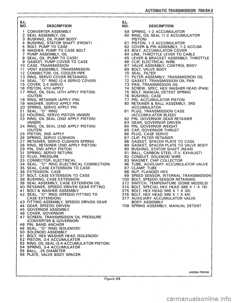
AUTOMAT lC TRANSMISSION 700-R4-3
ILL. NO. DESCRIPTION
1 CONVERTER ASSEMBLY
2 SEAL ASSEMBLY, OIL
3 BUSHING, OIL PUMP BODY
4 BUSHING, STATOR SHAFT (FRONT)
5 BOLT, PUMP TO CASE
6 WASHER, PUMP TO CASE BOLT
7 PUMP ASSEMBLY, OIL
8 SEAL, OIL (PUMP TO CASE)
9 GASKET, PUMP COVER TO CASE
10 CASE, TRANSMISSION
11 VENT ASSEMBLY, TRANSMISSION
1 12 CONNECTOR, OIL COOLER PIPE 13 RING, SERVO COVER RETAINING
14 SEAL, "0" RlNG
(2-4 SERVO COVER)
15 COVER, 2-4 SERVO
16 PISTON, 4TH APPLY
17 RING, OIL SEAL
(4TH APPLY PISTON)
(OUTER)
18 RING, RETAINER (APPLY PIN)
19 WASHER, SERVO APPLY PIN
20 SPRING, SERVO APPLY PIN
21 SEAL,
"0" RlNG
22 HOUSING, SERVO PISTON (INNER)
23 RING, OIL SEAL
(2ND APPLY PISTON)
(INNER)
24 RING, OIL SEAL
(2ND APPLY PISTON)
(OUTER)
25 PISTON, 2ND APPLY
26 SPRING, SERVO CUSHION
27 RETAINER, SERVO CUSHION SPRING
28 RING, RETAINER
(2ND APPLY PISTON)
29 PIN, 2ND APPLY PISTON
31 SPRING, SERVO RETURN
32 PLUG, PRESSURE
33 CONNECTOR, ELECTRICAL
34 SEAL,
"0" RlNG (ELECTRICAL CONNECTION)
35 SEAL, CASE EXTENSION TO CASE
36 EXTENSION, CASE
37 BOLT, CASE EXTENSION TO
CASE 38 BUSHING, CASE EXTENSION
39 SEAL ASSEMBLY, CASE EXTENSION OIL
40 RETAINER, SPEEDO DRIVEN GEAR FITTING
41 BOLT
& WASHER ASSEMBLY
42 SEAL, "0" RlNG (SPEEDO FITTING TO
CASE EXTENSION)
43 FITTING ASSEMBLY, SPEEDO DRIVEN GEAR
44 GEAR, SPEEDO DRIVEN
45 GOVERNOR ASSEMBLY
46 COVER, GOVERNOR
47 SCREEN, TRANSMISSION OIL PRESSURE
(CONVERTER
81 GOVERNOR)
48 PIN, BAND ANCHOR
49 SEAL,
"0" RlNG (SOLENOID)
50 SOLENOID ASSEMBLY
51 BOLT, HEX WASHER HEAD (SOLENOID)
52 PISTON, 3-4 ACCUMULATOR
53 RING, OIL SEAL
(3-4 ACCUMULATOR PISTON)
54 SPRING, 3-4 ACCUMULATOR
55 BALL,
.25 DIAMETER 56 PLATE, VALVE BODY SPACER
ILL. NO. DESCRIPTION
59 SPRING, 1-2 ACCUMULATOR
60 RING, OIL SEAL (1
-2 ACCUMULATOR
PISTON)
61 PISTON, 1-2 ACCUMULATOR
62 COVER
& PIN ASSEMBLY, 1-2 ACCUM.
63 BOLT, ACCUMULATOR COVER
64 LINK, THROTTLE LEVER TO CABLE
65 LEVER
& BRACKET ASSEMBLY, THROTTLE
66 CLIP, ELECTRICAL WIRE
67 VALVE ASSEMBLY, CONTROL BODY
69 BOLT, VALVE BODY
70 SEAL, FILTER
71 FILTER ASSEMBLY, TRANSMISSION OIL
72 GASKET, TRANSMISSION OIL PAN
73 PAN, TRANSMISSION OIL
74 SCREW, SPEC. HEX WASHER HEAD (PAN)
75 BOLT, MANUAL DETENT SPRING
76 BUSHING, CASE
77 PIN, ACCUMULATOR PISTON
80 RETAINER
& BALL ASSEMBLY, 3RD
ACCUMULATOR
81 PLUG, TRANSMISSION CASE
(ACCUMULATOR BLEED)
82 PIN, GOVERNOR GEAR RETAINER
83 GEAR, GOVERNOR DRIVEN
84 PIN, GOVERNOR WEIGHT
85 CAP, GOVERNOR THRUST
86 PLUG, CASE SERVO
87 CLIP, FILTER RETAINER
88 GASKET, SPACER PLATE TO CASE
89 GASKET, SPACER PLATE TO VALVE BODY
90 BUSHING, STATOR SHAFT
(REAR)
91 BALL, CARBON STEEL (T.V. EXHAUST)
92 CONDUIT, SOLENOID WIRE
93 MAGNET, CHIP COLLECTOR
96 TUBE, AUXILIARY ACCUMULATOR VALVE
97 CLAMP, TUBE
98 NUT, FLANGED HEX
99 SPEED SENSOR, INTERNAL
TRANSMISSIOr 100 BOLT, SPEEDO SENSOR RETAINING
372 SWITCH, TEMPERATURE (SOME MODELS)
374 BOLT, SPECIAL HEX HEAD (M6 X
1 X 16)
375 BOLT, HEX HEAD (M6 X 1 X
35) 376 BOLT, HEX HEAD (M6 X 1 X 45)
377 AUXILIARY ACCUMULATOR VALVE
BODY ASSEMBLY
709 SPRING ASSEMBLY, MANUAL DETENT
Figure 68
Page 1055 of 1825
700.R4.4 AUTOMATIC TRANSMISSION
TRANSMISSION DISASSEMBLY
General Service Information
e Teflon Oil Seal Rings
If any seal rings are damaged, cut, or do not
rotate freely in their groove be certain to check
the ring groove for debris, burrs, or damage.
s Thrust Washer Surfaces
The thrust washer and thrust bearing surfaces
may appear to be polished. This is a normal
condition and should not be considered damage.
Thoroughly clean the exterior of the
transmission.
Remove or Disconnect
e 'Torque Converter (1)
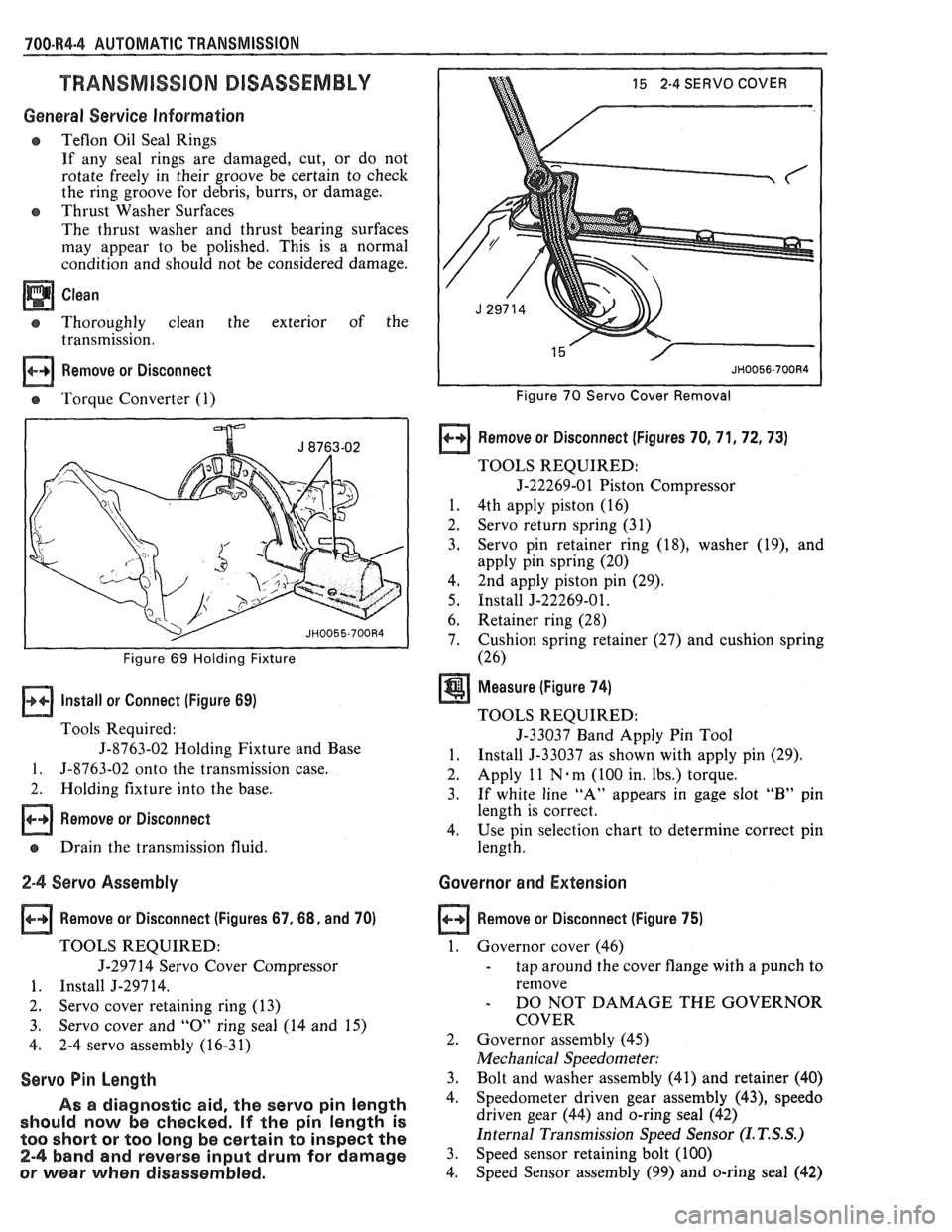
I I Figure 69 Holding Fixture
Install or Connect (Figure 69)
Tools Required:
J-8763-02 Holding Fixture and Base
1. 5-8763-02 onto the transmission case.
2. Holding fixture into the base.
Remove or Disconnect
e Drain the transmission fluid.
2-4 Servo Assembly
Remove or Disconnect (Figures 67,68, and 70)
TOOLS REQUIRED:
J-297 14 Servo Cover Compressor
1. Install J-29714.
2. Servo cover retaining ring (13)
3. Servo cover and
"0" ring seal (14 and 15)
4. 2-4 servo assembly (16-31)
Servo Pin Length
As a diagnostic aid, the servo pin length
should now be checked.
If the pin length is
too short
or too long be certain to inspect the
2-4 band and reverse input drum for damage
or wear when disassembled.
15 2-4 SERVO COVER
Figure 70 Servo Cover Removal
Remove or Disconnect (Figures 70, 71,72,73)
TOOLS REQUIRED:
5-22269-01 Piston Compressor
1. 4th apply piston (16)
2. Servo return spring (31)
3. Servo pin
retainer ring
(18), washer (19), and
apply pin spring (20)
4, 2nd apply piston
pin (29).
5. Install J-22269-01.
6. Retainer ring
(28)
7. Cushion spring
retainer (27) and cushion spring
(26)
Measure (Figure 74)
TOOLS REQUIRED:
5-33037 Band Apply Pin Tool
1. Install 5-33037 as shown with apply pin (29).
2. Apply
1 1 N . m
(100 in. lbs.) torque.
3. If white line "A" appears in gage slot "B" pin
length is correct.
4. Use pin selection chart to determine correct pin
length.
Governor and Extension
Remove or Disconnect (Figure 75)
1. Governor cover (46)
- tap around the cover flange with a punch to
remove
- DO NOT DAMAGE THE GOVERNOR
COVER
2. Governor assembly (45)
Mechanical Speedometer:
3. Bolt and washer assembly (41) and retainer (40)
4. Speedometer driven gear assembly (43), speedo
driven gear (44) and o-ring seal (42)
Internal Transmission Speed Sensor
(I. T. S.S.)
3. Speed sensor retaining bolt (100)
4. Speed
Sensor assembly
(99) and o-ring seal (42)
Page 1058 of 1825
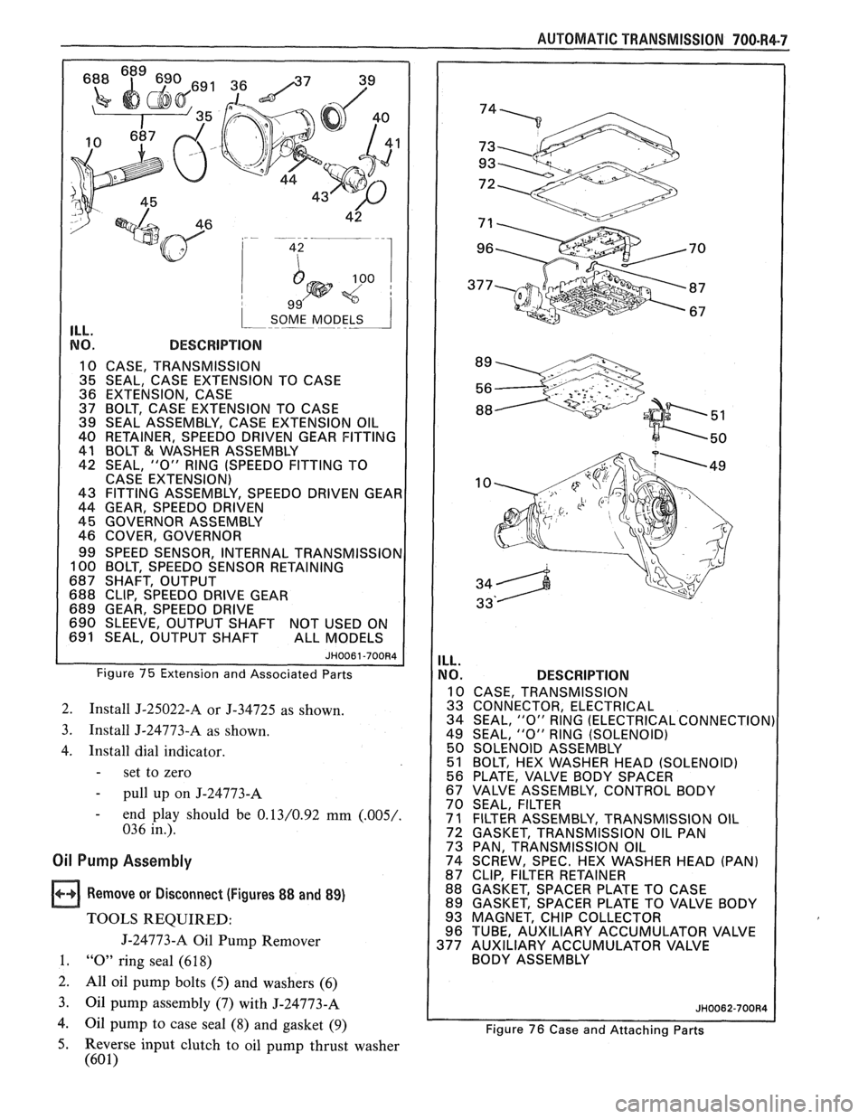
1 SOME MODELS 1 ILL.
NO. DESCRIPTION
10 CASE, TRANSMISSION
1 35 SEAL, CASE EXTENSION TO CASE
36 EXTENSION, CASE
37 BOLT,
CASE EXTENSION TO CASE
39 SEAL ASSEMBLY, CASE EXTENSION OIL
40 RETAINER, SPEEDO
DRIVEN GEAR FITTING
41 BOLT
& WASHER ASSEMBLY
42 SEAL,
"0" RlNG (SPEEDO FITTING TO
CASE EXTENSION)
43 FITTING ASSEMBLY, SPEEDO DRIVEN GEAI
44 GEAR, SPEEDO DRIVEN
45 GOVERNOR ASSEMBLY
46 COVER, GOVERNOR
99 SPEED SENSOR, INTERNAL
TRANSMISSIOI 100 BOLT, SPEEDO SENSOR RETAINING
687 SHAFT, OUTPUT
688 CLIP, SPEEDO DRIVE GEAR
689 GEAR, SPEEDO DRIVE
690 SLEEVE, OUTPUT SHAFT NOT USED ON
691 SEAL, OUTPUT SHAFT ALL MODELS
Figure 75 Extension and Associated Parts
2. Install J-25022-A or J-34725 as shown.
3. Install J-24773-A as shown.
4. Install dial indicator.
- set to zero
- pull up on J-24773-A
- end play should be 0.13/0.92 mm (.005/.
036 in.).
Oil Pump Assembly
Remove or Disconnect (Figures 88 and 89)
TOOLS REQUIRED:
J-24773-A Oil Pump Remover
1. "0" ring seal (6 18)
2.
All oil pump bolts (5) and washers (6)
3.
Oil pump assembly (7) with J-24773-A
4. Oil pump to case seal (8) and gasket (9)
AUTOMATIC TRANSMISSION 700-R4-7
ILL.
NO. DESCRIPTION
10 CASE, TRANSMISSION
33 CONNECTOR, ELECTRICAL
34 SEAL,
"0" RlNG (ELECTRICAL CONNECTION)
49 SEAL,
"0" RlNG (SOLENOID)
50 SOLENOID ASSEMBLY
51 BOLT, HEX WASHER HEAD (SOLENOID)
56 PLATE. VALVE BODY SPACER
/ 67 VALVE' ASSEMBLY, CONTROL BODY
70 SEAL, FILTER
1 71 FILTER ASSEMBLY, TRANSMISSION OIL
72 GASKET, TRANSMISSION OIL PAN
73 PAN, TRANSMISSION OIL
74 SCREW, SPEC. HEX WASHER HEAD (PAN)
87 CLIP, FILTER RETAINER
88 GASKET, SPACER PLATE TO CASE
89 GASKET, SPACER PLATE TO VALVE BODY
93 MAGNET, CHIP COLLECTOR
96 TUBE, AUXILIARY ACCUMULATOR VALVE
377 AUXILIARY ACCUMULATOR VALVE
BODY ASSEMBLY
Figure 76 Case and Attaching Parts
5. Reverse input clutch to oil pump thrust washer
(60 1)
Page 1063 of 1825
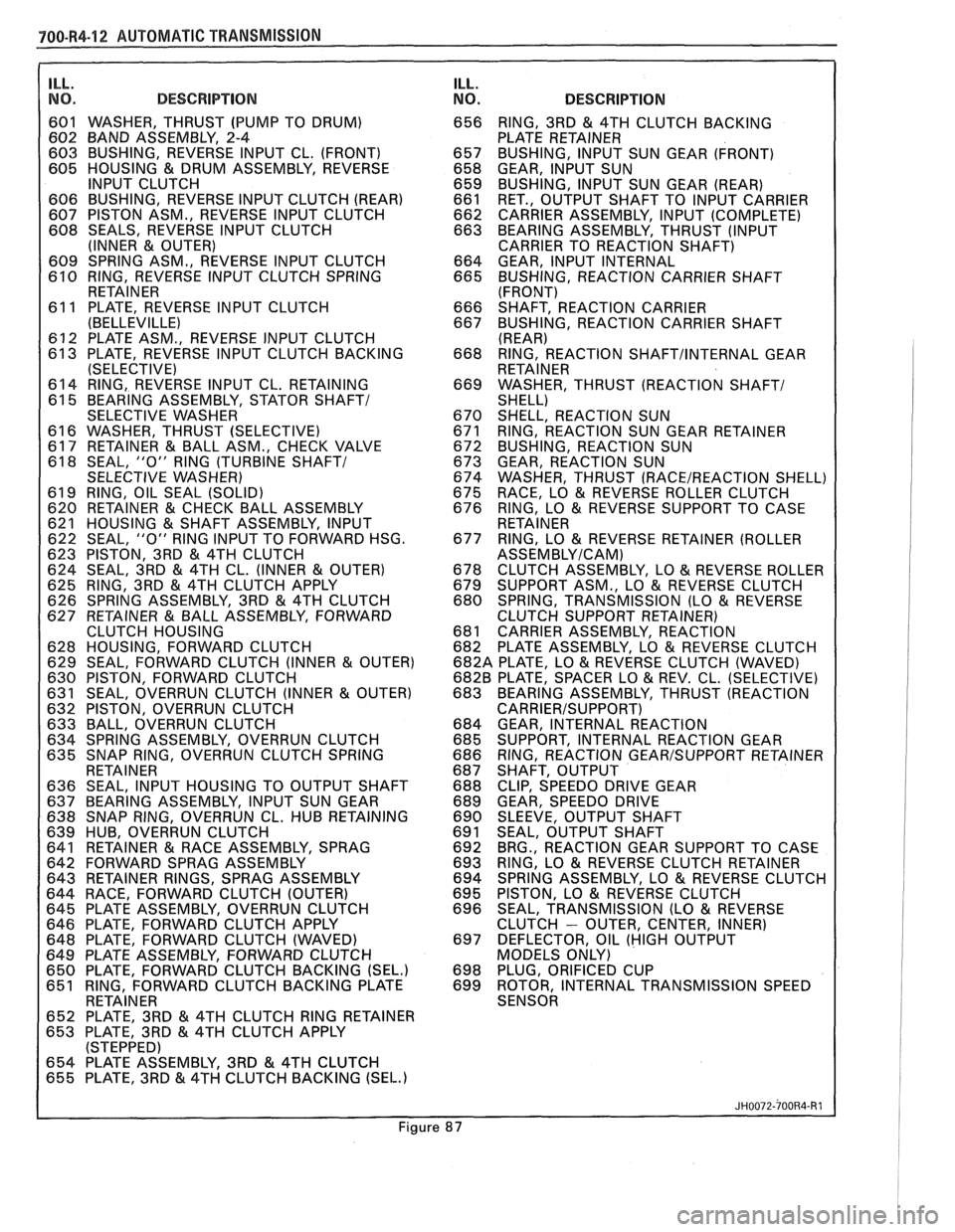
700-R4-12 AUTOMATIC TRANSMISSION
ILL.
I NO. DESCRIPTION
601 WASHER, THRUST (PUMP TO DRUM)
602 BAND ASSEMBLY, 2-4
603 BUSHING, REVERSE INPUT CL. (FRONT)
605 HOUSING
& DRUM ASSEMBLY, REVERSE
INPUT CLUTCH
606 BUSHING, REVERSE INPUT CLUTCH (REAR)
607 PISTON ASM., REVERSE INPUT CLUTCH
608 SEALS, REVERSE INPUT CLUTCH
(INNER
& OUTER)
609 SPRING ASM., REVERSE INPUT CLUTCH
610 RING, REVERSE INPUT CLUTCH SPRING
RETAINER
61 1 PLATE. REVERSE INPUT CLUTCH
(BELLEVILLEI
612 PLATE ASM., REVERSE INPUT CLUTCH
613 PLATE, REVERSE INPUT CLUTCH BACKING
(SELECTIVE)
614 RING, REVERSE INPUT CL. RETAINING
61 5 BEARING ASSEMBLY, STATOR
SHAFT1
SELECTIVE WASHER
61 6 WASHER, THRUST (SELECTIVE)
617 RETAINER
& BALL ASM., CHECK VALVE
61 8 SEAL, "0" RlNG (TURBINE SHAFT/
SELECTIVE WASHER)
61 9 RING, OIL SEAL (SOLID)
620 RETAINER
& CHECK BALL ASSEMBLY
621 HOUSING & SHAFT ASSEMBLY, INPUT
622 SEAL, "0" RlNG INPUT TO FORWARD HSG.
623 PISTON, 3RD
& 4TH CLUTCH
624 SEAL, 3RD & 4TH CL. (INNER & OUTER)
625 RING, 3RD
& 4TH CLUTCH APPLY
626 SPRING ASSEMBLY, 3RD & 4TH CLUTCH
627 RETAINER & BALL ASSEMBLY, FORWARD
CLUTCH HOUSING
628 HOUSING, FORWARD CLUTCH
629 SEAL, FORWARD CLUTCH (INNER
& OUTER)
630 PISTON, FORWARD CLUTCH
631 SEAL, OVERRUN CLUTCH (INNER
& OUTER)
632 PISTON, OVERRUN CLUTCH
633 BALL, OVERRUN CLUTCH
634 SPRING ASSEMBLY, OVERRUN CLUTCH
635 SNAP RING, OVERRUN CLUTCH SPRING
RETAINER
636 SEAL, INPUT HOUSING TO OUTPUT SHAFT
637 BEARING ASSEMBLY, INPUT SUN GEAR
638 SNAP RING, OVERRUN CL. HUB RETAINING
639 HUB, OVERRUN CLUTCH
641 RETAINER
& RACE ASSEMBLY, SPRAG
642 FORWARD SPRAG ASSEMBLY
643 RETAINER RINGS, SPRAG ASSEMBLY
644 RACE, FORWARD CLUTCH (OUTER)
645 PLATE ASSEMBLY, OVERRUN CLUTCH
646 PLATE, FORWARD CLUTCH APPLY
648 PLATE, FORWARD CLUTCH (WAVED)
649 PLATE ASSEMBLY, FORWARD CLUTCH
650 PLATE. FORWARD CLUTCH BACKING
(SEL.) 651 RING, FORWARD CLUTCH BACKING PLATE I RETAINER
I
. . - . . . . . . - . .
652 PLATE, 3RD & 4TH CLUTCH RlNG RETAINER
653 PLATE, 3RD & 4TH CLUTCH APPLY
(STEPPED)
654 PLATE ASSEMBLY, 3RD
& 4TH CLUTCH
655 PLATE, 3RD & 4TH CLUTCH BACKING (SEL.)
ILL.
NO. DESCRIPTION
656 RING, 3RD & 4TH CLUTCH BACKING
PLATE RETAINER
657 BUSHING, INPUT SUN GEAR (FRONT)
658 GEAR, INPUT SUN
659 BUSHING, INPUT SUN GEAR (REAR)
661 RET., OUTPUT SHAFT TO INPUT CARRIER
662 CARRIER ASSEMBLY, INPUT (COMPLETE)
663 BEARING ASSEMBLY, THRUST (INPUT
CARRIER TO REACTION SHAFT)
664 GEAR, INPUT INTERNAL
665 BUSHING, REACTION CARRIER SHAFT
(FRONT)
666 SHAFT, REACTION CARRIER
667 BUSHING, REACTION CARRIER SHAFT
(REAR)
668 RING, REACTION
SHAFTIINTERNAL GEAR
RETAINER
669 WASHER, THRUST (REACTION
SHAFT1 SHELL)
670 SHELL, REACTION SUN
671 RING, REACTION SUN GEAR RETAINER
672 BUSHING, REACTION SUN
673 GEAR, REACTION SUN
674 WASHER, THRUST
(RACE/REACTION SHELL)
675 RACE, LO & REVERSE ROLLER CLUTCH
676 RING, LO & REVERSE SUPPORT TO CASE
RETAINER
677 RING, LO
& REVERSE RETAINER (ROLLER
ASSEMBLYICAM)
678 CLUTCH ASSEMBLY, LO & REVERSE ROLLER
679 SUPPORT ASM., LO & REVERSE CLUTCH
680 SPRING, TRANSMISSION (LO & REVERSE
CLUTCH SUPPORT RETAINER)
681 CARRIER ASSEMBLY, REACTION
682 PLATE ASSEMBLY, LO
& REVERSE CLUTCH
682A PLATE, LO & REVERSE CLUTCH (WAVED)
682B PLATE, SPACER LO
& REV. CL. (SELECTIVE)
683 BEARING ASSEMBLY, THRUST (REACTION
CARRIERISUPPORT)
684 GEAR, INTERNAL REACTION
685 SUPPORT, INTERNAL REACTION GEAR
686 RING, REACTION
GEARISUPPORT RETAINER
687 SHAFT, OUTPUT
688 CLIP, SPEEDO DRIVE GEAR
689 GEAR, SPEEDO DRIVE
690 SLEEVE, OUTPUT SHAFT
691 SEAL, OUTPUT SHAFT
692 BRG., REACTION GEAR SUPPORT TO CASE
693 RING, LO
& REVERSE CLUTCH RETAINER
694 SPRING ASSEMBLY, LO & REVERSE CLUTCH
695 PISTON,
LO & REVERSE CLUTCH
696 SEAL,
TRANSMISSION (LO & REVERSE
CLUTCH - OUTER, CENTER, INNER)
697 DEFLECTOR, OIL (HIGH OUTPUT
MODELS ONLY)
698 PLUG.
ORIFICED CUP
699 ROTOR, INTERNAL TRANSMISSION SPEED
SENSOR
Figure