sensor PONTIAC FIERO 1988 Service Repair Manual
[x] Cancel search | Manufacturer: PONTIAC, Model Year: 1988, Model line: FIERO, Model: PONTIAC FIERO 1988Pages: 1825, PDF Size: 99.44 MB
Page 960 of 1825
INDEX
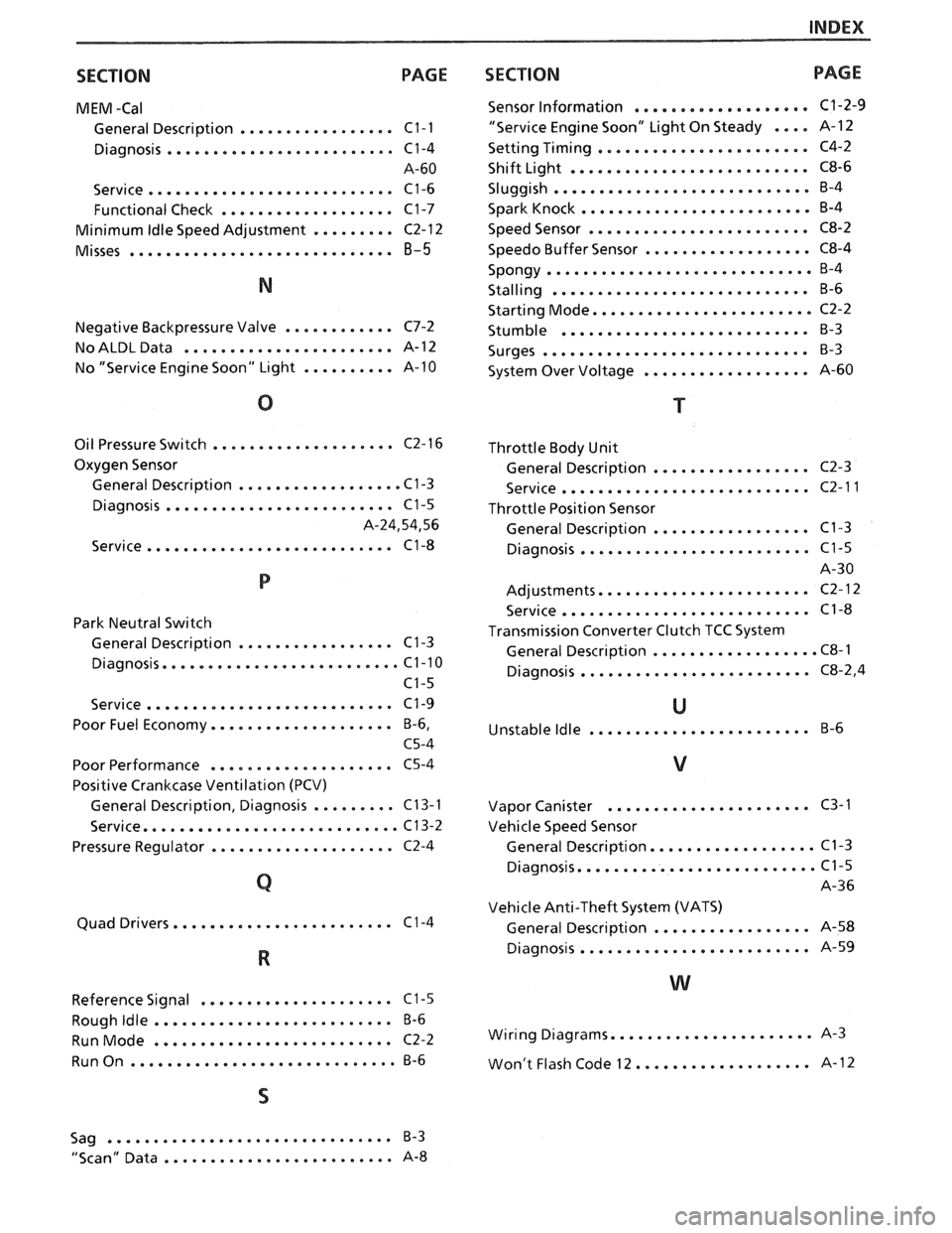
SECTION
PAGE
MEM -Cal
General Description ................. C1-I
Diagnosis ......................... C1-4
A-60
Service
........................... C1-6
Functional Check
................... C1-7
Minimum
Idle Speed Adjustment ......... C2-12
Misses ............................. 8-5
Negative Backpressure Valve ............ C7-2
No ALDL Data
....................... A- 12
No "Service Engine Soon" Light
.......... A-10
.................... Oil Pressure Switch C2-16
Oxygen Sensor
General Description
.................. C1-3
......................... Diagnosis C1-5
A.24.54. 56
........................... Service C1-8
Park Neutral Switch
General Description
................. C1-3
Diagnosis
.......................... C1-10
C1-5
Service
........................... C1-9
Poor Fuel Economy
.................... B.6.
C5-4
Poor Performance
.................... C5-4
Positive Crankcase Ventilation (PCV)
General Description. Diagnosis
......... C13-1
Service
............................ C13-2
Pressure Regulator
.................... C2-4
........................ Quad Drivers C 1-4
..................... Reference Signal C1-5
.......................... Rough Idle B-6
RunMode .......................... C2-2
RunOn ............................. B-6
SECTION PAGE
................... Sensor Information C1-2-9
"Service Engine Soon" Light On Steady .... A- 12
................... Setting Timing ... . C4-2
.......................... Shift Light C8-6
Sluggish
............................ B-4
......................... Spark Knock B-4
........................ Speed Sensor C8-2
.................. Speedo Buffer Sensor C8-4
Spongy
............................. B-4
............................ Stalling B-6
........................ Starting Mode C2-2
........................... Stumble B-3
Surges
............................. B-3
.................. System Over Voltage A-60
Throttle Body Unit
................. General Description C2-3
........................... Service C2-11
Throttle Position Sensor
................. General Description C1-3
......................... Diagnosis C1-5
A-30
....................... Adjustments C2-12
........................... Service C1-8
Transmission Converter Clutch TCC System
.................. General Description C8-1
......................... Diagnosis C8.2. 4
U
........................ Unstable Idle B-6
V
...................... Vapor Canister C3-1
Vehicle Speed Sensor
.................. General Description C1-3
.......................... Diagnosis C1-5
A-36
Vehicle Anti-Theft System (VATS)
................. General Description A-58
......................... Diagnosis A-59
W
...................... Wiring Diagrams A-3
................... Won't Flash Code 12 A-
12
Sag
.................+............. B-3
......................... "Scan" Data A-8
Page 962 of 1825
DRIVEABILITY AND EMISSIONS . FUEL INJECIION 6E-1
DRBVEABILIW AND EMISSIONS
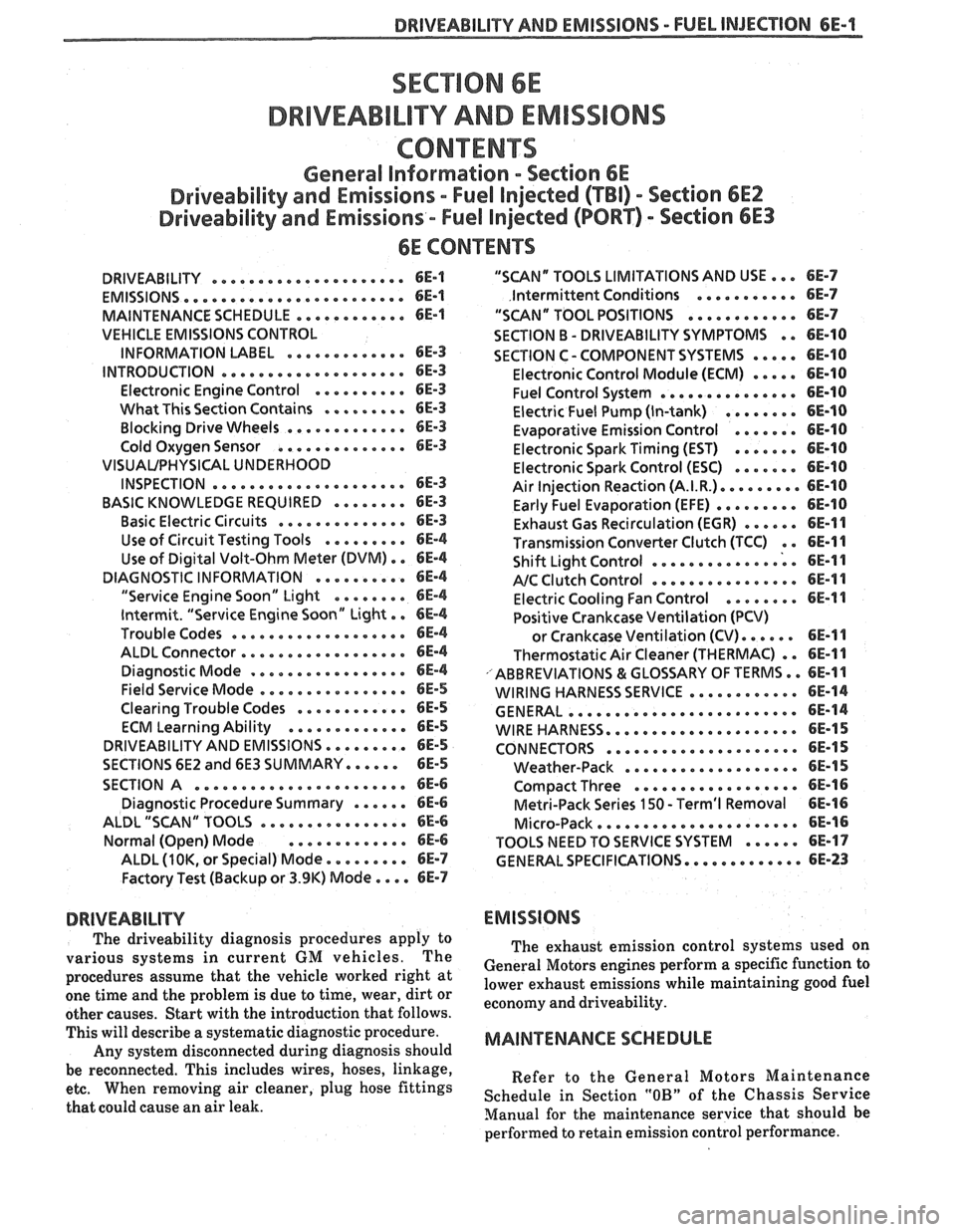
CONEENTS
General Information . Section 6E
Driveability and Emissions . Fuel Injected (TBI) . Section 6EZ
Driveability and Emissions . Fuel injected (PORT) . Section 6E3
..................... DRIVEABILITY 6E-1
........................ EMISSIONS 6E-1
MAINTENANCE SCHEDULE ............ 6E-1
VEHICLE EMISSIONS CONTROL
............. INFORMATION UBEL 6E-3
.................... INTRODUCTION 6E-3
.......... Electronic Engine Control 6E-3
What This Section Contains .......*. 6E-3
............. Blocking Drive Wheels 6E-3
.............. Cold Oxygen Sensor 6E-3
VISUAUPHYSICAL UNDERWOOD
..................... INSPECTION 6E-3
BASIC KNOWLEDGE REQUIRED ........ 6E-3
.............. Basic Electric Circuits 6E-3
Use of Circuit Testing Tools ......... 6E-4
Use of Digital Volt-Ohm Meter (DVM) . . 6E-4
DIAGNOSTIC INFORMATION .......... 6E-4
"Service Engine Soon" Light ........ 6E-4
Intermit . "Service Engine Soon" Light . . 6E-4
................... Trouble Codes 6E-4
.................. ALDL Connector 6E-4
Diagnostic Mode ................. 6E-4
Field Service Mode ................ 6E-5
............ Clearing Trouble Codes 6E-5
............. ECM Learning Ability 6E-5
DRIVEABILITY AND EMISSIONS ......... 6E-5
SECTIONS 6E2 and 6E3 SUMMARY ...... 6E-5
SECTION A ....................... 6E-6
Diagnostic Procedure Summary ...... 6E-6
ALDL "SCAN" TOOLS ................ 6E-6
Normal (Open) Mode ............. 6E-6
ALDL (1 OK. or Special) Mode ......... 6E-7
Factory Test (Backup or 3.9K) Mode .... 6E-7
DRIVEABILITY
The driveability diagnosis procedures apply to
various systems in current GM vehicles
. The
procedures assume that the vehicle worked right at
one time and the problem is due to time, wear. dirt or
other causes
. Start with the introduction that follows .
This will describe a systematic diagnostic procedure .
Any system disconnected during diagnosis should
be reconnected
. This includes wires, hoses. linkage.
etc . When removing air cleaner. plug hose fittings
that could cause an air leak
.
"SCAN" TOOLS LIMITATIONS AND USE ... 6E-7
Intermittent Conditions ........... 6E-7
"SCAN" TOOL POSITIONS ............ 6E-7
SECTION B . DRIVEABILITY SYMPTOMS . . 6E-10
SECTION C- COMPONENT SYSTEMS ..... 6E-10
Electronic Control Module (ECM) ..... 6E-10
Fuel Control System ............... 6E-10
Electric Fuel Pump (In-tank) ........ 6E-10
....... Evaporative Emission Control 6E-10
Electronic Spark Timing (EST) ....... 6E-10
....... Electronic Spark Control (ESC) 6E-10
Air Injection Reaction (A.I.R.). ........ 6E-10
......... Early Fuel Evaporation (EFE) 6E-10
Exhaust Gas Recirculation (EGR) ...... 6E-11
Transmission Convefler Clutch (TCC) . . 6E-11
.............. Shift Light Control ; . 6E-I I
................ NC Clutch Control 6E-11
........ Electric Cooling Fan Control 6E-11
Positive Crankcase Ventilation (PCV)
...... or Crankcase Ventilation (CV) 6E-11
Thermostatic Air Cleaner (THERMAC) . . 6E-11
ABBREVIATIONS & GLOSSARY OF TERMS .. 6E-1 1
............ WIRING HARNESS SERVICE 6E-14
......................... GENERAL 6E-14
WIREHARNESS.... ............*.... 6E-15
CONNECTORS .....e..e..ee...~.e.. 6E-15
................... Weather-Pack 6E-15
.................. Compact Three 6E-16
Metri-Pack Series 150 . Terrn'l Removal 6E-16
...................... Micro-Pack 6E-16
...... TOOLS NEED TO SERVICE SYSTEM 6E-17
GENERAL SPECIFICATIONS ............. 6E-23
EMISSIONS
The exhaust emission control systems used on
General Motors engines perform a specific function to
lower exhaust emissions while maintaining good fuel
economy and driveability
.
MAINTENANCE SCHEDULE
Refer to the General Motors Maintenance
Schedule in Section
"OB" of the Chassis Service
Manual for the maintenance service that should be
performed to retain emission control performance
.
Page 964 of 1825
DRIVEABILITY AND EMISSIONS - FUEL INJECTION 6E-3
VEHICLE EMISSION CONTROL INFORMATION
MBEL
The Vehicle Emission Control Information label
(Figure
1) contains important emission specifications
and setting procedures. In the upper left corner is
exhaust emission information which identifies the
year, the manufacturing division of the engine, the
displacement in liters of the engine, the class of
vehicle and type of fuel metering. Also there is an
illustrated emission component and vacuum hose
schematic. A similar label is located in the engine
compartment of every General Motors Corporation
vehicle. If the label has been removed, it can be
ordered from the parts division.
(WDDGM)
INTRODUCTION
Electronic Engine Control
Each engine has an electronic engine control
module
(ECM) to control the fuel system. The ECM
varies the
airlfuel ratio by controlling the fuel flow
through the
injectorb).
In addition, the ECM controls the ignition timing
as well as the fuel pump and other systems.
It is important to review the component sections
and wiring diagrams in Section
"6E2" and "6E3" for a
specific engine, to determine what is controlled by the
ECM and what systems are
non-ECM controlled.
What This Section Contains
Each General Motors engine has system controls
to reduce exhaust emissions while maintaining good
driveability and fuel economy. This section explains:
@ Wow to use the Driveability and Emission
Sections
"6E2" for TBI, and "6E3" for Port
Fuel engines.
A brief description of systems used to control
fuel and emissions.
@ Abbreviations that are used in "Driveability
and Emissions".
@ Wiring harness service information for
harnesses used with the ECM.
@ Special tools used to diagnosis and repair a
system. Before
checking the system, observe the following:
Blocking Drive Wheels
The vehicle drive wheels always should be
blocked, and parking brake firmly set, while checking
the system.
Cold Oxygen Sensor
On some engines, the oxygen sensor will cool off
after only a short period of operation at idle. This will
put the system into "Open Loop". To restore "Closed
Loop" operation, run the engine at part throttle and
accelerate from idle to part throttle a few times until
the system goes "Closed Loop".
VlSUAUPHYSlCAL UNDERHOOD
INSPE6"rON
This can often lead to fixing a problem without further
steps. Inspect all vacuum hoses for correct routing,
pinches, cuts, or disconnects. Be sure to inspect hoses
that are difficult to see beneath the air cleaner,
compressor, generator, etc. Inspect all the wires in the
engine compartment for correct and good connections,
burned or chafed spots, pinched wires, or contact with
sharp edges or hot exhaust manifolds. This
visual/physical inspection is very important. It must ,
be done carefully and thoroughly.
BASIC KNOWLEDGE REQUIRED
Before using this section of the service manual,
there are some areas that you should be familiar with.
Without this basic knowledge, you will have trouble
using the diagnostic procedures contained in this
section.
Basic Electric Circuits
You should understand the basic theory of
electricity, and know the meaning of voltage, amps,
ALL NEW GENERAL MOTORS VEHICLES ARE CERTIFIED BY THE UNITED STATES
ENVIRONMENTAL PROTECTION
AGENCY AS CONFORMING TO THE REQUIREMENTS OF THE
REGULATIONS
FOR THE CONTROL OF AIR POLLUTION FROM NEW MOTOR VEHICLES. THlS
CERTIFICATION IS CONTINGENT OM CERTAIN ADJUSTMENTS BEING SET TO FACTORY
STANDARDS. IN MOST CASES, THESE ADJUSTMENT
POINTS EITHER HAVE BEEN
PERMANENTLY SEALED
AND/OR MADE INACCESSIBLE TO PREVENT INDISCRIMINATE OR
ROUTINE ADJUSTMENT IN THE FIELD. FOR
THlS REASON, "TI- FACTORY PROCEDURE FOR
TEMPORARILY REMOVING PLUGS, CAPS, ETC., FOR PURPOSES OF SERVICING THE PRODUCT,
MUST BE STRICTLY FOLLOWED AND, WHEREVER PRACTICABLE, RETURNED
TO WE
ORIGINAL INTENWF THE DESIGN.
Page 965 of 1825
6E-4 DRIVEABILITY AND EMISSIONS - FUEL INJECnON
and ohms. You should understand what happens in a
circuit with an open or a shorted wire. You should be
able to read and understand a wiring diagram. A
short to ground
is referred to as a ground to
distinguish it from a short between wires.
Use of Circuit Testing Tools
You should know how to use a test light, how to
connect and use
a tachometer, and how to use jumper
wires to by-pass components to test circuits. Care
should be taken to not deform the terminal when
testing.
Use of Digital Volt-Ohm Meter (DVM)
You should be familiar with the digital volt-ohm
Meter, particularly essential tool J-29125-A,
J34029A
or equivalent. You should be able to measure voltage,
resistance, and current, and know how to use the
meter correctly.
The digital volt-ohm meter is covered in the
"Special
ToolsJ'portion of this section.
DIAGNOSTIC INFORMATION
The electronic control module (ECM) is equipped
with a self-diagnosis system which detects system
failure and aids the technician by identifying the
circuit at fault via a trouble code. Below is
information about the way the ECM displays a
problem and how this corresponds to a trouble code in
the ECM. The ECM can also indicate an "Open Loop"
or "Closed Loop" mode.
"'Service Engine Soonw Light
This light is on the instrument panel, and has two
functions:
@ It is used to tell the driver that a problem has
occurred, and that the vehicle should be taken for
service as soon as reasonably possible.
@ It is used by the technician to read out "Trouble
CodesJ' to help diagnose system problems.
As a bulb and system check, the light will come
"ON" with the key "ON" and the engine not running.
When the engine is started, the light will turn "OFF".
If the light remains "ONJ', the self-diagnostic system
has detected a problem. If the problem goes away, the
light will go out in most cases after 10 seconds, but a
Trouble Code will remain stored in the ECM.
Intermittent "Service Engine Soon" Light
The diagnostic charts in Section "A" are set up to
check whether or not a stored trouble code is
"intermittent" or "hard". An
"intermittent" code is one which does not
always reset when the code setting parameters are
met, or is not present while you are working on the
vehicle. This is often caused by
a loose connection.
The facing page will contain diagnostic aids to help in
detecting
intermittents.
A "hard" code is one which is present when you
are working on the vehicle and the condition still
exists while working on the vehicle. The chart with
the stored trouble code number will lead you to the
cause of the problem.
Trouble Codes
The engine control module (ECM) is really a
computer. It uses sensors to look at many engine
operating conditions. It has
a memory and it knows
what certain sensor readings should be under certain
conditions. These conditions are described on the
facing page of each Trouble Code chart. If a sensor
reading is not what the ECM thinks it should be, the
ECM will turn "ON" the "Service Engine Soon" light
on the instrument panel, and will store a Trouble Code
in the memory. The Trouble Code tells which circuit
the trouble is in. A circuit consists of a sensor (such as
coolant temperature), the wiring and connectors to it,
and the ECM.
i
To get a Trouble Code out of the ECM, we use the
assembly line diagnostic link (ALDL) connector.
!
ALDL Connector I
I
The assembly line diagnostic link (ALDL) is a
diagnostic connector located in the passenger
compartment (Figure 2). It has terminals which are
used in the assembly plant to check that the engine is
operating properly before it leaves the plant.
Terminal "B" is the Diagnostic terminal, and it can be
connected to terminal
"A", or ground, to enter the
Diagnostic mode, or the Field Service Mode.
The ALDL connector is also used by "ScanJ' tools to
read information from the ECM via the Serial Data
Line. Serial Data information
is used extensively
throughout the manual.
Diagnostic Mode
1
If the Diagnostic terminal is grounded with the
ignition "ON" and the engine stopped, the system will
enter the Diagnostic Mode. In this mode the ECM
will:
1. Display a Code 12 by flashing the "Service Engine
Soon" light (indicating the system is operating). A
Code 12 consists of one flash, followed by a short
pause, then two flashes in quick succession. This
code will be flashed three times. If no other codes
Page 968 of 1825
DRIVEABILITY AND EMISSIONS - FUEL INJECTION 6E-7
On engines that can be monitored in the open
mode, it allows certain parameters to be obtained
without changing the engine operating
characteristics. The parameters capable of being read
vary from engine family to engine family. Most
"Scan" tools are programmed so that the system will
go directly into the special mode
if the "open" mode is
not available.
ALDL (7 OK, or Special) Mode
(not used on
all engines)
In this mode, all information incorporated into a
specific
engine and ECM is obtainable. However, in
this mode the system operating characteristics are
modified as follows.
@ "Closed Loop" timers are bypassed
EST (spark) is advanced
@ IAC will control engine idle to 1000 rpm I
50 rpm (if applicable)
@ On some engines, canister purge solenoid will
be enabled
@ P/N restrict functions will be disabled.
Factory Test (Back-up or 3.9 K) Mode
(TBI, Port)
In this mode, the ECM is operating on the fuel
back-up logic and is calibrated by the Calpak or Mem-
cal. These are used to control the fuel delivery
if the
ECM fails. This mode verifies that the back-up feature
is OK. The parameters that can be read on a
"Scan"
tool in this mode are not of much use for service.
"SCAN" TOOL LIMITATIONS AND USE
The "Scan" tool allows a quick check of sensors
and switches which are inputs to the ECM. However,
on some applications the data update rate makes the
tool less effective as a voltmeter when trying to detect
an intermittent which lasts for a very short time.
However, the "Scan" tool allows one to manipulate
wiring harnesses or components under the hood while
observing the "Scan" readout. This helps in locating
intermittents with the engine not running.
intermittent Conditions
for a period of time to see if there is any change in the
readings that indicates intermittent operation.
The "Scan" tool is also a useful and quick way of
comparing operating parameters of a poorly operating
engine with a known good one. For example;
A sensor
may shift in value but not set a code. Comparing with
a known good vehicle may uncover the problem.
The "Scan" tool has the ability to save time in
diagnosis and prevent the replacement of good parts.
The key to using the "Scan" tool successfully for
diagnosis lies in the technician's ability to understand
the system he is trying to diagnose as well as an
understanding of the "Scan" tool's limitations.
Therefore, the technician should read the tool
manufacturer's operating manual to become familiar
with the operation. The following information will
describe most of the "Scan" tool positions and how
they can be helpful in diagnosis.
"SCAN" TOOL POSITIONS
The following positions may not be applicable to
all engines. See the facing page
of the diagnostic
circuit check for a particular engine to decide which
positions apply to that engine.
Mode
Check with the manufacturer to determine what
the function of this mode is. In most cases it allows the
user to place the ECM in different operating modes.
Injector Pulse Width
In this position, the reading is given in
milliseconds, which is the
"ON" time that the ECM is
commanding to the
injector(s1.
Closed LoopIOpen Loop
This position will indicate whether the engine
control system is operating in "Open Loop" or "Closed
Loop". Most systems go "Closed Loop" after a certain
amount of running time, when coolant temperature is
high enough, and the oxygen sensor becomes active.
Exhaust (RichILean Indicator)
The "Scan" tool is helpful in cases of intermittent
This indicates the O2 sensor voltage at the instant operation' The can be in and observed that the data stream is sampled. If voltage is less than
while driving the vehicle under the condition where
350 mv, the value will be lean. If above 550 mv, a rich the light comes "ON" momentarily, or the engine exhaust is indicated. driveability is poor momentarily. If the problem
seems to be related to certain areas that can be
Codes checked on the "Scan" tool, then those are the
positions that should be checked while driving the
This will display any trouble codes stored in the
vehicle. If there does not seem to be any correlation
ECM memory. between the problem and any specific circuit, the
"Scan" tool can be checked on each position, watching
Page 969 of 1825
6E-8 DRIVEABILITY AND EMISSIONS - FUEL INJECTION
Throttle Position Sensor (TPO) Coolant Q~erature
Values read will be the voltage as seen by the Engine
temperature is displayed in Celsius
ECM. The voltage should be the TPS specification degrees.
After the engine is started, temperature
with the throttle closed and go up to about 5 volts should
rise steadily to about
85-95" C, then stabilize
with throttle wide open
(WOT). when the thermostat opens.
Throttle Angle
Displayed, in percent, is the amount the throttle is
open. 0% is closed throttle, 100% is wide open throttle.
Oxygen (Of) Sensor
The reading will be read out in millivolts (mv)
with a range from 1 to 999 mv. If the reading is
consistently below 350 (350 mv), the fuel system
is
running lean as seen by the ECM; and if the reading is
consistently above 550 (550 mv), the system is
running rich.
In this position, information is used for assembly
verification only. PROM ID is useful only when the
vehicle
is equipped with the original ECM and PROM
or Mem-Cal.
Reading displays engine rpm. It is often useful if
extra reference pulses are suspected. A sudden high
rpm indication while at a steady throttle would
indicate electrical interference
(EMI) in the reference
circuit. This interference
is usually caused by ECM
wires too close to ignition secondary wires or an open
distributor ground circuit.
Displayed is vehicle speed, useful in checking TCC
application speed or speedometer accuracy.
MAF
This displays the amount of air passing the Mass
Air Flow
(MAF) sensor, in grams per second. It is
useful when comparing the airflow between a problem
vehicle and a known good one. Normal readings at
idle are about
4 to 8 grams. If a MAF code is set, this
reading will display the ECM default value.
This display should be the same as MAF when
there are no failures in the MAP sensor circuit. When
an MAF code is set, however, this value will not
change, and will indicate the
grn/sec that the failure
has detected.
Manifold Air Temperature (MAT) Sensor
This displays temperature of the intake manifold
air. It should read close to ambient air temperature
when the engine is cold, and rise as underhood and
engine temperatures increase.
Manifold Absolute Pressure (MAP)
The MAP sensor produces a low signal voltage
when manifold pressure is low (high vacuum) and a
high voltage when the pressure is high (low vacuum).
With the ignition "ON" and the engine stopped,
I
the manifold pressure is equal to atmospheric
pressure, and the signal voltage will be high. This 1
information is used by the ECM as an indication of
vehicle altitude and is referred to as BARO.
Comparison of this
BARO reading with a known good
vehicle with the same sensor is a good way to check
accuracy of a "suspect" sensor
*. Readings should be
the same
+ .4 volt. I
* A MAP sensor has a colored plastic insert visible I I
in the connector cavity. Sensors with the same insert I
color are identical in calibration. The harness I
I
electrical connector color also should be the same as 1 the sensor insert color.
I Vacuum (Differential Pressure) Sensor
The vacuum sensor produces a low signal voltage
when manifold vacuum is low, and a high voltage
when the vacuum is high.
With the ignition "ON" and the engine stopped,
there is no vacuum, so the voltage is low (under
1
volt). With the engine idling the vacuum is high so the
voltage is high (over
3 volts).
A vacuum sensor has a colored plastic insert
visible in the connector cavity. Sensors with the same
insert color are identical in calibration. The harness
electrical connector color also should be the same as
the sensor insert color.
This displays barometric pressure. The ECM uses
this information to adjust for altitude and pressure.
This value will vary depending on barometric
pressure and altitude. Some vehicles use a dedicated
bar0 sensor, while others take a MAP reading before
the engine is started, and at various times during
engine operation.
Page 971 of 1825
6E-18 DRIVEABILITY AND EMISSIONS - FUEL INJECRON
CCP (Carbon Canister Purge)
This displays "ON" when the canister purge
solenoid is commanding purge. Some display duty
cycle from
0-1008.
2nd Gear
This displays the state of the 2nd gear switch.
Yes=2nd gear applied. It remains applied in 3rd and
4th gears.
3rd Gear
This displays the state of the 3rd gear switch.
Yes= 3rd gear applied. It remains applied in 4th gear.
4th Gear
This displays the state of the 4th gear switch.
Yes
= 4th gear applied.
Fan Request
State of the AJC fan control switch is displayed. It
should read "yes" when fan is requested. Some
engines may display the state of the 2nd fan, if used.
Power Steering Pressure Switch
This reading displays the state of switch, and may
vary with the tool used, and the type of switch
installed on the vehicle. The important thing is that
the reading changes state (switches) when the
steering is moved against the stops.
Electronic Control Module (ECM)
This section describes the ECM and the
information sensors in the system. Figure
4 shows
the operating conditions which the ECM may sense
and the systems that the ECM may control. (See
specific engines to determine which are applicable
to
that engine.)
Fuel Control System
The ECM controls the aidfuel delivery to the
combustion chamber by controlling the fuel flow
through the
injector(s).
Electric Fuel Pump (In-tank)
The in-tank fuel pump is controlled by the ECM.
When ignition is turned "ON", the pump will run for 2
seconds, then stop unless the ECM is receiving
ignition pulses, as when cranking or running.
Evaporative Emission ControI
This system has a canister which stores fuel vapor
from the fuel tank. The fuel vapor is removed from the
canister and consumed in the normal combustion
process when the engine is running. This system is
used on all engines and may or may not be controlled
by the ECM.
ilectronic Spark Timing (EST)
This system is controlled by the ECM, which
controls spark advance (timing), and is used on all
engines.
SECTION B - DRIVEABILIW SYMPTOMS Electronic Spark
Control (ESC)
Always start with Section "A" "Diagnostic Circuit
Check" before proceeding to the driveability
symptoms or an emissions test failure. Section "A"
checks the ECM, which may cause the driveability
problem. A definition of each symptom is included.
This will then lead to the most probable causes of the
driveability problem.
SECTION C - COMPONENT SYSTEMS
There are many component systems that are used
to control fuel and emissions. Section
"C" introduces
each component system or control with a general
description, diagnosis, and on-vehicle service.
Each of the Section "C" diagnosis sections contain
information on how the "ScanJ' tool can be used for
diagnosing a particular component when a trouble
code has not been set. (example: Section
"Cl" under
diagnosis will explain how the "Scan" tool can be used
for diagnosis as well as what the normal readings
would be for the
ECM sensors.) This
system uses a knock sensor in connection
with the ECM to control spark timing, to allow the
engine to have maximum spark advance without
spark knock. This improves driveability and fuel
economy, but will retard spark
if detonation (spark
knock) is detected.
Air Injection Reaction (A.I.R.)
The system provides additional oxygen to the
exhaust gases to continue the combustion process.
The system also supplies additional air to the catalytic
converter under certain conditions. The A.I.R. system
is not on all engines.
Early Fuel Evaporation (EFE)
The EFE system heats the engine induction
system electrically or with exhaust gas during cold
Page 972 of 1825
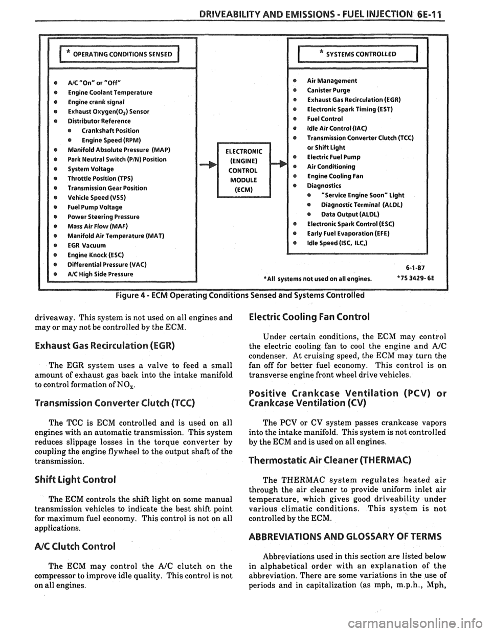
DRIVEABILITY AND EMISSIONS - FUEL INJEC"F0N 6E-11
@ A/% "On" or "Off" r Air Management
r Engine Coolant Temwrature r Canister Purge
@ Engine crank signal r Exhaust Gas Recirculation (EGR)
@ Exhaust Oxygen(02) Sensor @ Electronic Spark Timing (EST)
r Distributor Reference @ Fuel Control
@ Crankshaft Position @ Idle Air Control (lAC)
@ Engine Speed (RPM) Transmission Converter Clutch (TCC)
Manifold Absolute Pressure (MAP)
@ Park Neutral Switch (PB) Position @ Electric Fuel Pump
r System Voltage Air Conditioning
r Throttle Position (TPS) @ Engine Cooling Fan
r Transmission Gear Position
r Vehicle Speed (VSS) @ "Service Engine Soon" Light
@ Fuel Pump Voltage @ Diagnostic Terminal (ALDL)
r Power Steering Pressure @ Data Output (ALDL)
Mass Air Flow (MAF) @ Electronic Spark Control (ESC)
@ Manifold Air Temperature (MAT) @ Early Fuel Evaporation (EFE)
r EGR Vacuum @ Idle Speed (ISC, ILC,)
@ Engine Knock (ESC)
r Differential Pressure (VAC) 6-1-87
*7S
3429- 6E
Figure
4 - ECM Operating Conditions Sensed and Systems Controlled
driveaway. This system is not used on all engines and Electric Cooling Fan Control
may or may not be controlled by the ECM.
Under certain conditions, the
ECM may control
Exhaust Gas Recirculation (ECR) the electric cooling fan to cool the engine and A/C
condenser. At cruising speed, the ECM may turn the
The
EGR system uses a valve to feed a small fan
off for better fuel economy. This control is on
amount of exhaust gas back into the intake manifold transverse
engine front wheel drive vehicles.
to control formation of
NO,.
Positive Crankcase Ventilation (PCV) or
Transmission Converter
Clutch (TCC) Crankcase Ventilation (CV)
The TCC is ECM controlled and is used on all
engines with an automatic transmission. This system
reduces slippage losses in the torque converter by
coupling the engine flywheel to the output shaft of the
transmission.
Shift Light Control
The ECM controls the shift light on some manual
transmission vehicles to indicate the best shift point
for maximum fuel economy. This control is not on all
applications.
NC Clutch Control
The ECM may control the AJC clutch on the
compressor to improve idle quality. This control is not
on all engines. The
PCV or CV system passes crankcase vapors
into the intake manifold. This system is not controlled
by the
ECM and is used on all engines.
Thermostatic Air Cleaner (THERMAC)
The THERMAC system regulates heated air
through the air cleaner to provide uniform inlet air
temperature, which gives good driveability under
various climatic conditions. This system is not
controlled by the
ECM.
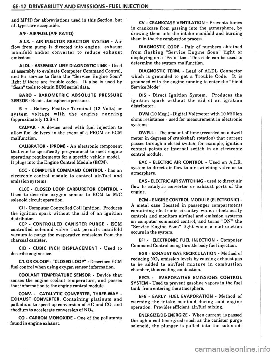
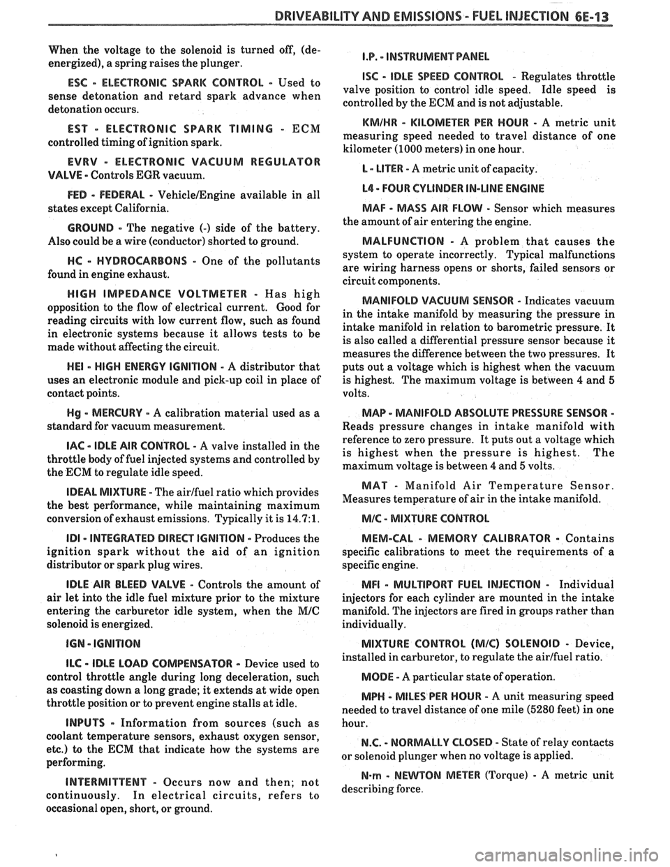
ABBREVIATIONS AND GLOSSARY OF TERMS
Abbreviations used in this section are listed below
in alphabetical order with an explanation of the
abbreviation. There are some variations in the use of
periods and in capitalization (as mph,
m.p.h., Mph,
Page 973 of 1825
6E-12 DRIVEABILITY AND EMISSIONS - FUEL INJECUION
and MPH) for abbreviations used in this Section, but
all types are acceptable.
NA/F - AI WFUEL (NF RATIO)
A.I.R.
- AIR INJECTOR REACTION SYSTEM - Air
flow from pump is directed into engine exhaust
manifold
and/or converter to reduce exhaust
emissions.
ALDL - ASSEMBLY LINE DIAGNOSTIC LINK - Used
at assembly to evaluate Computer Command Control,
and for service to flash the "Service Engine Soon"
light
if there are trouble codes. It also is used by
"Scan" tools to obtain ECM serial data.
BARO - BAROMETRIC ABSOLUTE PRESSURE
SENSOR
- Reads atmospheric pressure.
B + - Battery Positive Terminal (12 Volts) or
system voltage with the engine running
(approximately 13.8
v.)
CALPAK - A device used with fuel injection to
allow fuel delivery in the event of a PROM or ECM
malfunction.
CALIBRATOR - (PROM) - An electronic component
that can be
specifically programmed to meet engine
operating requirements for a
specific vehicle model.
It plugs into the Engine Control Module
(ECM).
CCC - COMPUTER COMMAND CONTROL - has an
electronic control module to control airlfuel and
emission systems.
CLCC - CLOSED LOOP CARBURETOR CONTROL -
Used to describe oxygen sensor to ECM to MIC
solenoid circuit operation.
C3I - Computer Controlled Coil Ignition. Produces
the ignition spark without the aid of an ignition
distributor.
CCP - CONTROLLED CANISTER PURGE - ECM
controlled solenoid valve that permits manifold
vacuum to purge the evaporative emissions from the
charcoal canister.
CID - CUBIC INCH DISPLACEMENT - Used to
describe engine size.
UL OR ULOOP - "CLOSED LOOP" - Describes ECM
fuel control when using oxygen sensor information.
COOLANT TEMPERATURE SENSOR - Device that
senses the engine coolant temperature, and passes
that information to the engine control module.
CONV. - CATALYTIC CONVERTER, THREE-WAY -
EXHAUST CONVERTER. Containing platinum and
palladium to speed up conversion of
HC and CO, and
rhodium to accelerate conversion of NO,.
CO - CARBON MONOXIDE - One of the pollutants
found in engine exhaust.
6V - CRANKCASE VENTlhaflON - Prevents fumes
in crankcase from passing into the atmosphere, by
drawing them into the intake manifold and burning
them in the the combustion process.
DIAGNOSTIC CODE - Pair of numbers obtained
from flashing "Service Engine Soon" light or
displaying on a "Scan" tool. This code can be used to
determine the system malfunction.
DIAGNOSTIC TERM. - Lead of ALDL Connector
which is grounded to get a Trouble Code.
It is
grounded with the engine running to enter the "Field
Service Mode".
DIS - Direct Ignition System. Produces the
ignition spark without the aid of an ignition
distributor.
DVM (10 Meg.) - Digital Voltmeter with 10 Million
ohms resistance
- used for measurement in electronic
systems.
DWELL - The amount of time (recorded on a dwell
meter in degrees of crankshaft rotation) that current
passes through a closed switch; for example, ignition
contact points or internal switch in an electronic
control module.
EAC - ELECTRIC AIR CONTROL - Used on A.I.R.
system to direct air flow to air switching valve or to
atmosphere.
EAS - ELECTRIC AIR SWITCHING - used to direct air
flow to catalytic converter or exhaust ports of the
engine.
ECM - ENGINE CONTROL MODULE (ELECTRONIC) -
A metal case (located in passenger compartment)
containing electronic circuitry which electrically
controls and monitors airlfuel and emission systems
on computer command control, and turns
"ON" the
"Service Engine Soon" light when a malfunction
occurs in the system.
EFI - ELECTRONIC FUEL INJECTION - Computer
Command Control using throttle body fuel injection.
EGR - EXHAUST GAP REClRCUbATlON - Method of
reducing NO, emission levels by causing exhaust gas
to be added to airlfuel mixture in combustion
chamber, thus cooling combustion.
EECS - EVAPORATIVE EMISSIONS CONTROL
SYSTEM
- Used to prevent gasoline vapors in the fuel
tank from entering the atmosphere.
EFE - EARLY FUEL EVAPORATION - Method of
warming the intake manifold during cold engine
operation. Provides efficient airlfuel mixing.
ENERGIZEIDE-ENERGIZE - When current is passed
through a coil (energized) such as the canister purge
solenoid, the plunger is pulled into the solenoid.
Page 974 of 1825
DRIVEABILIW AND EMISSIONS - FUEL INJECTION 6E-13
When the voltage to the solenoid is turned off, (de-
energized), a spring raises the plunger.
ESC - ELECTRONIC SPARK CONTROL - Used to
sense detonation and retard spark advance when
detonation occurs.
EST - ELECTRONIC SPARK TIMING - ECM
controlled timing of ignition spark.
EVRV - ELECTRONIC VACUUM REGULAWR
VALVE - Controls EGR vacuum.
FED - FEDEWL - VehicleIEngine available in all
states except California.
GROUND - The negative (-) side of the battery.
Also could be a wire (conductor) shorted to ground.
HC - HYDROCARBONS - One of the pollutants
found in engine exhaust.
HIGH IMPEDANCE VOLTMETER - Mas high
opposition to the flow of electrical current.
Good for
reading circuits with low current flow, such as found
in electronic systems because it allows tests to be
made without affecting the circuit.
HE1 - HIGH ENERGY IGNITION - A distributor that
uses an electronic module and pick-up coil in place of
contact points.
Hg - MERCURY - A calibration material used as a
standard for vacuum measurement.
IAC - IDLE AIR CONTROL - A valve installed in the
throttle body of fuel injected systems and controlled by
the ECM to regulate idle speed.
IDEAL MIXWRE - The airlfuel ratio which provides
the best performance, while maintaining maximum
conversion of exhaust emissions. Typically it is
14.7:1.
ID1 - INTEGRATED DIRECT IGNITION - Produces the
ignition spark without the aid of an ignition
distributor or spark plug wires.
IDLE AIR BLEED VALVE - Controls the amount of
air let into the idle fuel mixture prior to the mixture
entering the carburetor idle system, when the
MIC
solenoid is energized.
ILC - IDLE LOAD COMPENSATOR - Device used to
control throttle angle during long deceleration, such
as coasting down a long grade; it extends at wide open
throttle position or to prevent engine stalls at idle.
INPUTS - Information from sources (such as
coolant temperature sensors, exhaust oxygen sensor,
etc.) to the ECM that indicate how the systems are
performing.
INTERMITTENT - Occurs now and then; not
continuously. In electrical circuits, refers to
occasional open, short, or ground.
I.P. - INSTRUMENT PANEL
ISC - IDLE SPEED CONTROL - Regulates throttle
valve position to control idle speed. Idle speed is
controlled by the ECM and is not adjustable.
KMIHR - KILOMEnR PER HOUR - A metric unit
measuring speed needed to travel distance of one
kilometer (1000 meters) in one hour.
L - LITER - A metric unit of capacity.
L4 - FOUR CYLINDER IN-LINE ENGINE
MAF - MASS AIR FLOW - Sensor which measures
the amount of air entering the engine.
MALFUNCTION - A problem that causes the
system to operate incorrectly. Typical malfunctions
are wiring harness opens or shorts, failed sensors or
circuit components.
MANIFOLD VACUUM SENSOR - Indicates vacuum
in the intake manifold by measuring the pressure in
intake manifold in relation to barometric pressure. It
is also called a differential pressure sensor because
it
measures the difference between the two pressures. It
puts out a voltage which is highest when the vacuum
is highest. The maximum voltage is between 4 and 5
volts.
MAP - MANIFOLD ABSOLUTE PRESSURE SENSOR -
Reads pressure changes in intake manifold with
reference to zero pressure. It puts out a voltage which
is highest when the pressure is highest. The
maximum voltage is between
4 and 5 volts.
MAT - Manifold Air Temperature Sensor.
Measures temperature of air in the intake manifold.
MIC - MIXTURE CONTROL
MEM-CAL
- MEMORY CALIBRATOR - Contains
specific calibrations to meet the requirements of a
specific engine.
MFI - MULTlPORT FUEL INJECnON - Individual
injectors for each cylinder are mounted in the intake
manifold. The injectors are fired in groups rather than
individually.
MIXTURE CONTROL (MIC) SOLENOID - Device,
installed in carburetor, to regulate the airlfuel ratio.
MODE - A particular state of operation.
MPH - MILES PER HOUR - A unit measuring speed
needed to travel distance of one mile (5280 feet) in one
hour.
N.C. - NORMALLY CLOSED - State of relay contacts
or solenoid plunger when no voltage is applied.
N-rn - NEWTON METER (Torque) - A metric unit
describing force.