battery location PONTIAC FIERO 1988 Service Owner's Guide
[x] Cancel search | Manufacturer: PONTIAC, Model Year: 1988, Model line: FIERO, Model: PONTIAC FIERO 1988Pages: 1825, PDF Size: 99.44 MB
Page 1338 of 1825

HEATER
TROUBLESMOOTlNG HINTS
e Try the following checlcs before doing the
System Check.
1. If the Blower Motor does not operate at all,
check the
HTR A/C Fuse.
2. If the Blower Motor does not operate at all,
check that
GI08 is clean and tight.
3. If the Blower Motor does not turn off, in-
stall
a new Blower Switch.
r Go to System Check for a guide to normal
operation.
r Go to System Diagnosis for diagnostic tests.
SYSTEM CHECK
Use the System Check Table as a guide to
normal operation.
e Refer to System Diagnosis for a list of symp-
toms and diagnostic steps.
SYSTEM CHECK TABLE
ACTION 1 NORMALRESUU 1
COMPONENT LOCATION Page-Figure
Blower Motor (Without
AlC) ....... RH front of dash, behind strut tower .......... 201-14-D
Blower Resistors (Without AIC) .... RH front side of heater housing .............. 201-14-D
Fuse Block.
..................... Behind LH side of IIP, below light switch. ...... 201-10-8
C202 (1 cavity) .................. Behind center of UP, near control head. ........ 201-14-C
GPO8 .......................... RH front of dash, above center of Blower Motor . 201-14-D
SYSTEM DIAGNOSIS
Do the tests listed for your symptom in the
Symptom Table below.
Tests follow the Symptom Table.
SYMPTOM TABLE
A: BLOWER SWITCH TEST
0 If your symptom does not appear in the (A: BLOmR SWITCH TEST continued on Sympton Table perForm all of the Tests. next page)
not normal. Measure:
VOLTAGE
At: BLOWER
SWITCH CONNECTOR
(Connected)
Condition:
a ignition Switch: RUN
Measure Correct For
Between Voltage Diagnosis
P P
See 1
Blower Switch: LO
&
Ground Battery
See 2
* Blower
Switch: MED
(LT BLU)
& Ground
* Blower Switch: HI
Battery
See 2
Page 1389 of 1825
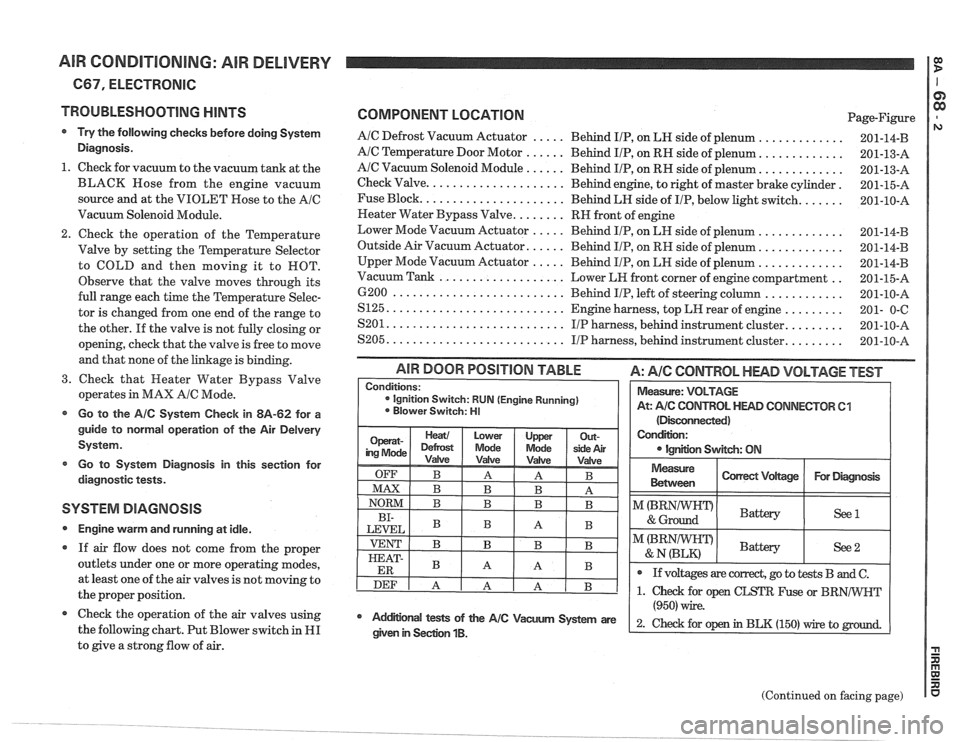
AIR CONDITIONING: AIR DELIVERY I g
667, ELECTRONIC
TROUBLESHOOTING
HINTS
Try the following checks before doing System
Diagnosis.
1. Check for vacuum to the vacuum tank at the
BLACK Hose from the engine vacuum
source and at the VIOLET Rose to the
AIC
Vacuum Solenoid Module.
Check the operation of the Temperature
Valve by setting the Temperature Selector
to COLD and then moving it to ROT.
Observe that the valve moves through its
full range each time the Temperature Selec-
tor is changed from one end of the range to
the other. If the valve is not fully closing or
opening, check that the valve is free to move
and that none of the linkage is binding.
3. Check that Heater Water Bypass Valve
operates in MAX
AIC Mode.
Go to the AIC System Check in 8A-62 for a
guide to normal operation of the Air
Delvery
System.
Go to System Diagnosis
in this section for
diagnostic tests.
SYSTEM DIAGNOSIS
Engine warm and running at idle.
If air flow does not come from the proper
outlets under one or more operating modes,
at least one of the air valves is not moving to
the proper position.
@ Check the operation of the air valves using
the following chart. Put Blower switch in
HI
to give a strong flow of air.
COMPONENT LOCATION Page-Figure
AIC Defrost Vacuum Actuator ..... Behind IIP, on LH side of plenum .............
AIC Temperature Door Motor ...... Behind IIP, on RH side of plenum. ............
AIC Vacuum Solenoid Module ...... Behind IIP, on RH side of plenum. ............
Check Valve. .................... Behind engine, to right of master brake cylinder.
Fuse Block.
..................... Behind LH side of IIP, below light switch. ......
Neater Water Bypass Valve. ....... RH front of engine
Lower Mode Vacuum Actuator
..... Behind IIP, on LH side of plenum .............
Outside Air Vacuum Actuator. ..... Behind IIP, on RH side of plenum. ............
Upper Mode Vacuum Actuator ..... Behind IIP, on LH side of plenum .............
.. Vacuum Tank ................... Lower LH front corner of engine compartment
6200
.......................... Behind IIP, left of steering column ............
S125. .......................... Engine harness, top LH rear of engine .........
........ S201. .......................... IIP harness, behind instrument cluster.
........ S205. .......................... IIP harness, behind instrument cluster.
(Disconnected)
Condition:
IgnEon Swgch: ON
AIR DOOR POSITION TABLE A: AIC CONTROL HEAD VOLTAGE TEST
Measure
Between I Correct Vdtage / For Diagmsk I
Conditions: ignition Switch: RUN (Engine Running)
Blower Switch: HI
I"(BRNIWIFDI & Ground Battery ( See1 I
Measure: VOLTAGE
At:
A/C CONTROL HEAD CONNECTOR 61
I I
@ If voltages are correct, go to tests B and C.
(Continued on facing page)
Mdifional tests of the AIC Vacum System are
(950) wire.
2- ~hd for op in BLK (150) rrire to given in Seclion 1B.
Page 1420 of 1825
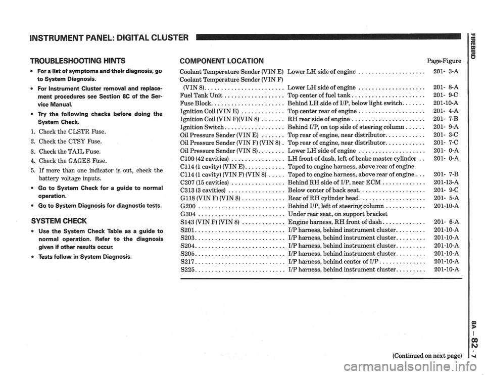
INSTRUMENT PANEL: DIGITAL CLUSTER a
TROUBLESHOOTING HINTS COMPONENT LOCATION u Page-Figure
0 For a list of symptoms and their diagnosis. go
to System Diagnosis
.
0 For Instrument Cluster removal and replace-
ment procedures see Section
86 of the Ser-
vice Manual
.
* Try the following checks before doing the
System Check
.
1 . Check the CLSTR Fuse .
2 . Check the CTSY Fuse .
3 . Check the TAIL Fuse .
Coolant Temperature Sender (VIN E) Lower LH side of engine ....................
Coolant Temperature Sender (VIN F)
(VIN 8)
........................ Lower LH side of engine ....................
Fuel Tank Unit .................. Top center of fuel tank ......................
Fuse Block ...................... Behind LH side of IIP. below light switch .......
Ignition Coil (VIN E) ............. Top center rear of engine ....................
Ignition Coil (VIN F)(VIN 8) ....... RH rear side of engine ......................
Ignition Switch .................. Behind IIP. on top side of steering column ......
Oil Pressure Sender (VIN E) ....... Top rear of engine. near distributor ............
Oil Pressure Sender (VIN F) (VIN 8) . Top rear of engine. near distributor ............
Oil Pressure Sender (VIN S) ........ Lower LH side of engine ....................
................ .. 4 . Check the GAGES Fuse . el00 (42 cavities) LH
front of dash. left of brake master cylinder 201- 0-A
C114
(1 cavity) (VIN E) ............ Taped to engine harness. above rear of engine
5 . If more than one indicator is out. check the C114 (1 cavity) (VIN F) (VIN 8) ..... Taped to engine harness. above rear of engine ... 201- 7-B
battery voltage inputs . . C207 (15 cavities) ................ Behind RH side of IIP near ECM ............. 201-13-A
................. .................... * Go to System Check for a guide to C313 (3 cavities) Below
center of back seat 201- 9-C operation . 6118 (VIN F) (VIN 8) ............. Rear of RH cylinder head .................... 201- 5-A
0 Go to System Diagnosis for diagnostic tests . 6200 .......................... Behind IIP. left of steering column ............ 201-10-A
6304
.......................... Under rear seat. on support bracket
SYSTEM CHECK S143 (VIN F) (VIN 8) ............. Engine harness. RH front of dash ............. 201- 6-A
0 Use the System Check able as a guide to S201 ........................... IIP harness. behind instrument cluster ......... 201-10-A
normal operation . Refer to the diagnosis S203 ........................... I/P harness. behind instrument cluster ......... 201-10-A
........................... ......... given if other results occur . S204 IIP harness. behind instrument cluster 201-10-A
........................... ......... Tests follow in System Diagnosis . S205 IIP harness. behind instrument cluster 201-10-A
S217 ........................... IIP harness. behind center of IIP .............. 201-10-A
S225 ........................... IIP harness. behind instrument cluster ......... 201-10-A
(Continued on next page)
Page 1437 of 1825
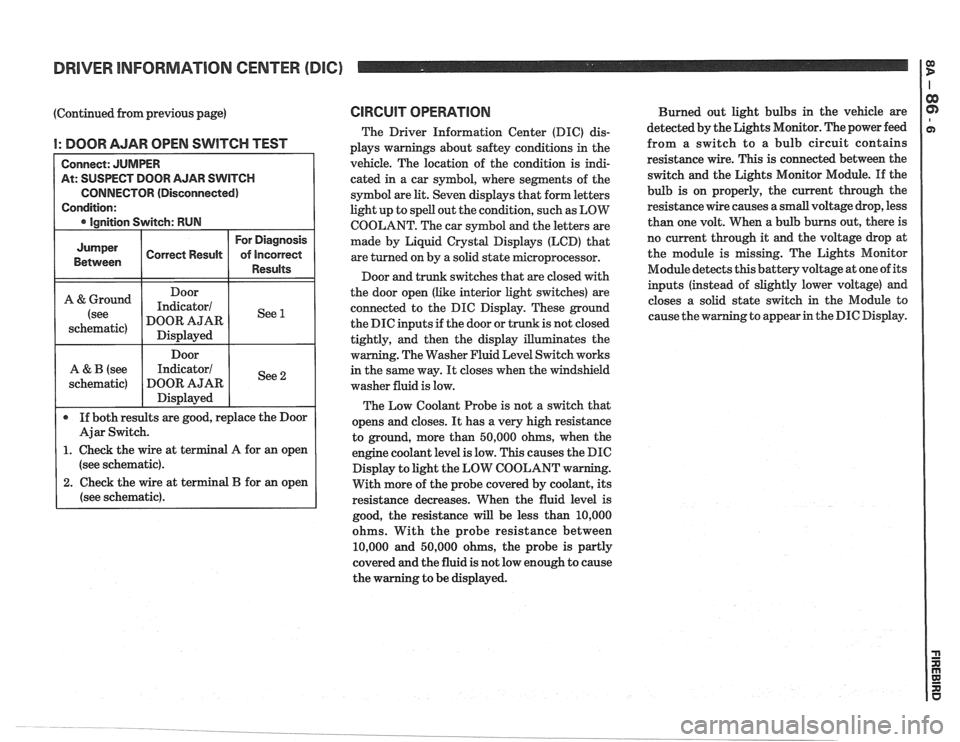
DRIVER INFORMATION CENTER (DIC) I $
(Continued from previous page)
I: DOOR AJAR OPEN SWITCH TEST
At: SUSPECT DOOR AJAR SWITCH
CONNECTOR (Disconnected)
(see schematic).
2. Check the wire at terminal B for an open
(see schematic).
CIRCUIT OPERATION
The Driver Information Center (DIC) dis-
plays warnings about
saftey conditions in the
vehicle. The location of the condition is indi-
cated in a car symbol, where segments of the
symbol are
lit. Seven displays that form letters
light up to spell out the condition, such as LOW
COOLANT. The car symbol and the letters are
made by Liquid
Crystal Displays (LCD) that
are turned on by a solid state microprocessor.
Door and trunk switches that are closed with
the door open (like interior light switches) are
connected to the DIC Display. These ground
the DIC inputs if the door or trunk is not closed
tightly, and then the display illuminates the
warning. The Washer Fluid Level Switch works
in the same way.
It closes when the windshield
washer fluid is low.
The Low Coolant Probe is not a switch that
opens and closes.
It has a very high resistance
to ground, more than 50,000 ohms, when the
engine coolant level is low. This causes the DIC
Display to light the LOW COOLANT w
With more of the probe covered by coolant, its
resistance decreases. When the fluid level is
good, the resistance
will be less than 10,000
ohms. With the probe resistance between
10,000 and 50,000 ohms, the probe is partly
covered and the fluid is not low enough to cause
the warning to be displayed. Burned
out light bulbs in the vehicle are
detected by the Lights Monitor. The power feed
from a switch to a bulb circuit contains
resistance wire. This is connected between the
switch and the Lights Monitor Module.
If the
bulb is on properly, the current through the
resistance wire causes a small voltage drop, less
than one volt. When a bulb burns out, there is
no current through it
and the voltage drop at
the module is missing. The Lights Monitor
Module detects this battery voltage at one of its
inputs (instead of slightly lower voltage) and
closes a solid state switch in the Module to
g to appear in the DIC Display.
Page 1450 of 1825
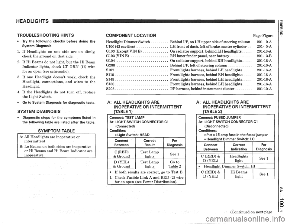
TROUBLESHOOTING HINTS COMPONENT LOCATION Page-Figure
* Try the following checks before doing the Headlight Dimmer Switch. ........ Behind IIP, on LH upper side of steering column. 201- 9-A
System Diagnosis. el00 (42 cavities) ................ LH front of dash, left of brake master cylinder .. 201- 0-A
.... ............. 1. If Headlights on one side are on dimly, 6103 (Except VIN E)
On radiator support, behind LH headlights. 201-16-A
........... ................... check the ground on that side. 6103 (VIN E) RN inner fender panel, near battery 201- 3-B
2. If Hi Beams do not light, but the Hi Beam
Indicator lights, check LT
GRN (11) wire
for an open (see schematic).
3. If one Headlight doesn't work, check the
Headlight, connections, and wires to the
Headlight.
4. If the Headlights do not turn off, replace
the Light Switch.
Go to System Diagnosis for diagnostic tests.
SYSTEM DIAGNOSIS
Diagnostic steps for the symptoms listed in
the following table are listed after the table.
SYMPTOM TABLE
A: All Headlights are inoperative or
intermittent
B: Lo Beams on both sides are inoperative
s and Hi Beam Indicator are
.... .......................... 6104 On radiator support, behind RH headlights. 201-16-A
............ 6200 .......................... Behind IIP, left of steering column 201-10-A
.... .......................... S107. Front lights harness, behind LH headlights. 201-16-A
.... .......................... S110. Front lights harness, behind RH headlights 201-16-A
.... .......................... S149. Front lights harness, behind LH headlights. 201-16-A
.... S150. .......................... Front lights harness, behind LH headlights. 201-16-A
........ S205. .......................... IIP harness, behind instrument cluster. 201-10-A
A: ALL HEADLIGHTS ARE
INOPERATIVE OR INTERMITTENT
(TABLE 1)
A: ALL HEADLIGHTS ARE
INOPERATIVE OR INTERMITTENT
(TABLE 21
Connect: TEST LAMP
At: LIGHT
SVVITCH CONNECTOR C1
(Connected)
Condition:
r Liaht Switch: HEAD
Connect Correct
Between Result Diagnosis
C (RED) Test Lamp
& Ground lights See 1
D
(YEL) Test Lamp
If both results are correct, go to Test B.
1 1. Check Fusible Link A and RED (2) wire
for an open (see Power Distribution).
Connect: FUSED JUMPER
At: LIGHT
SWITCH CONNECTOR C1
(Disconnected)
Conditions:
r Put a 15 amp fuse in the fused jumper
* Headliaiht Dimmer Switch: LO
I Connect 1 Correct ( or 1
Between I Indication 1 Diagnosis I I
I C (RED) & ( Heydlights I See D (YEL) ight
I Headlight Dimmer Switch: HI I
(Continued on next page
Page 1466 of 1825

HEADLIGHTS WlTH LAMP MONITOR: FOG LIGHTS
TROUBLESHOOTING MINTS
0 Try the following checks before doing the
System Diagnosis.
1. Check that the Headlights and Park Lights
work properly before troubleshooting the Fog
Lights.
2. If one Fog Light doesn't work, check the Fog
Light, connections, and wires to the Fog
Light.
3. If the Fog Light Switch is not illu
when the Park Lights are on, check the
GRU
(8) wire.
4.
If the FOG LIGHTS ON Light and the
Panel Light do not operate, check the BLK
(150) wire for an open.
Go to System Diagnosis for diagnostic tests.
SYSTEM DIAGNOSIS
Do the test below if the Fog Lights do not
operate.
FOG LIGHTS DO NClT OPEWTE
Measure: VOLTAGE
At: FOG
LIGHT RELAY CONNECTOR
(Disconnected)
Conditions:
r Light Switch: PARK
Fog Light Switch:
ON
Measure Correct
For Diagnosis
Belvveen
COMPONENT LOCATION Page-Figure
................. Fog Light Relay LH front
of engine compartment, on fender. .... 201-16-A
..................... Fuse Block. Behind
LH side of IIP, below light switch. ...... 201-10-A
Fusible Link A (VIN
E) ........... Lower RN side of engine, at Starter Solenoid. ... 201- 2-A
Fusible Link A (VIN F) (VIN 8)
..... Lower RH side of engine, at Starter Solenoid. ... 201- 6-B
Fusible Link A (VIN S). ........... Lower RH side of engine, at Starter Solenoid. ... 201- 1-A
.................. Fusible Link D Front lights harness, near LH side of dash. ..... 201-16-A
.................. Fusible Link E. Front lights harness, near LH side of dash. ..... 201-16-A
.................. Fusible Link G Front
lights harness, near LK side of dash. ..... 201-16-A
................. Remote Dimmer RH side of steering column, on IIP retainer ..... 201-10-A
................ el00 (42 cavities) LH front
of dash, left of brake master cylinder .. 201- 0-A
.................. 6103 (1 cavity). In
front lights harness, LH rear corner of engine
.......................... compartment.. 201-15-C
................. 6213 (3 cavities) Behind LH side
of IIP, near light switch. ....... 201-10-C
6103 (Except VIN E) ............. On radiator support, behind LK headlights. .... 201-16-A
.......................... 6104 On radiator support, behind RH headlights. .... 201-16-A
.......................... ............ 6200 Behind IIP, left of steering column 201-10-A
.......................... S105. Front lights harness, behind LH headlights. .... 201-16-A
.......................... S107. Front lights harness, behind LH headlights. .... 201-16-A
.......................... S110. Front lights harness, behind RH headlights .... 201-16-A
S165. .......................... Forward lights harness, LH front comer of
...................... engine compartment 201-15-B
.......................... S204. I/P harness, behind instrument cluster. ........ 201-10-A
.......................... S225. I/P harness, behind instrument cluster. ........ 201-10-A
.......................... ............... S236. IIP harness, below light switch 201-10-A
(BRNIWNT)
& Ground
(FOG LIGHTS DO
NOT OPERATE continued
on next page)
Battery
See
1
Page 1489 of 1825
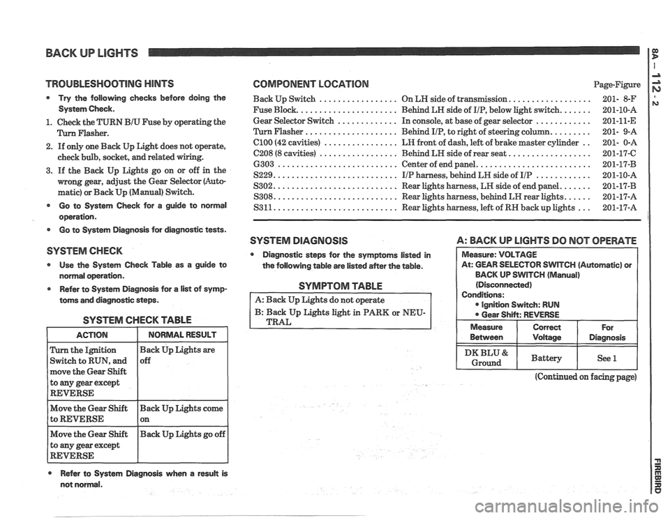
BACK UP LIGHTS
TROlJBLESHQOTlNG HINTS COMPONENT LOCATION Page-Figure
Try the following checks before doing the Back Up Switch ................. On LN side of transmission. ................. 201- 8-F
System Check. Fuse Block. ..................... Behind LH side of IIP, below light switch. ...... 201-10-A
............. ............ 1. Check the TURN BIU Fuse by operating the Gear
Selector Switch In
console, at base of gear selector
201-11-E
.................... Flasher. Flasher Behind IIP, to right of steering column. ........ 201- 9-A
2. If only one Back Up Light does not operate,
check bulb, socket,
and related
3. If the Back Up Lights go on or off in the
mong gear, adjust the Gear Selector (Auto-
matic) or Back Up (Manual) Switch.
el00 (42 cavities) ................ LR front of dash, left of brake master cylinder ..
C208 (8 cavities) ................. Behind LH side of rear seat. .................
6303 .......................... Center of end panel. ........................
S229. .......................... IIP harness, behind LH side of IIP ............
S302. .......................... Rear lights harness, LH side of end panel. ......
S308. .......................... Rear lights harness, behind LH rear lights. ..... - - Go to System Check for a guide to normal S3 11. .......................... Rear lights harness, left of RN back up lights
201-17-A ...
operation.
Go to System Diagnosis for diagnostic tests.
SYSTEM DlAGRlOSlS A: BACK UP LlGHTS DO NOT OPERATE
SYSTEM CHECK
Diagnostic steps for the symptoms listed in
Use the System Check Table as a guide to
the following table are listed
aMer the table. WlTCH (Automatic) or
normal operation. BACK
UP SWITCH
(Manual)
Refer to System Diagnosis for
a list of symp-
toms and diagnostic steps.
SYSTEM CHECK TABLE
the Ignition
Switch to RUN, and
move the Gear Shift
to
any gear except
REVERSE
Move the Gear Shift Back Up Lights come
to REVERSE 1 on - -
Move the Gear Shift Back
Up Lights go off
to any gear except
REVERSE
Refer to System Diagnosis when a result is
SYMPTOM TABLE
A: Back Up Lights do not operate
B: Back Up Lights light in PARK or NEU-
TRAL
(Continued on facing page)
not normal. Between
I Voltage I Diagnosis
I DKBLU& I Battery I See l I Ground
Page 1524 of 1825

HATCH PULL-DOWN
TROUBLESHOOTING H lNTS
Try the following checks before doing the
System Check.
1. Check that connector on Hatch Pull-Down
Unit is firmly seated.
2. Check Hatch Fuse by visual inspection.
* Go to System Check for a guide to normal
operation.
, * Go to System Diagnosis for diagnostic tests.
SYSTEM CHECK
Use the System Check Table as a guide to
normal operation;
Refer
to'system Diagnosis for diagnostic
steps.
SYSTEM CHECK TABLE
Striker rises to
and raise the lid
Lower the Hatch Striker retracts
slowly until lock
pulling Hatch dosed
hook on Hatch
Caution: to avoid
latches the striker
injury keep fingers
and clothing away
from edge of Natch
while it is closing
COMPONENT LOCATION Page-Figure
Hatch Fuse
..................... Attached to side of Fuse Block
..... Hatch Pull-Down Unit ............ Center of end panel, in cargo compartment
201-17-B
C208 (8 cavities)
................. Behind LH side of rear seat. ................. 201-17-C
SYSTEM DIAGNOSIS
Do the test below if the Hatch Pull-Down
Unit does not operate
At: HATCH
PULL-DOVVN UNIT (Connected)
I I
If voltages are correct but Hatch Pull-
Down Unit does not operate, replace Pull-
Down
Unit. (See Body Section 7 for dis-
assembly procedures).
1. Check REDIWHT (138) wire and Hatch
Fuse for an open.
Closing When the Hatch is lowered, the lock hook
latches the Striker, moving the Pull-Down Unit
Latch contacts to the LATCHED position. Voltage
is then applied to the motor in the reverse
disec-
tion. The motor moves the Striker down, pulling
the Hatch closed. Once the Natch is closed, the
Pull-Down Unit Striker contacts move to the
STRIKER FULLY PULLED DOWN position re-
moving the ground from the motor.
CIRCUIT OPERATION
Opening
When the Hatch is closed, the Latch contacts
and Striker contacts are
in the position shown
on the schematic. Voltage is applied at
all times
to the Hatch Pull-Down Unit through the
Hatch Fuse and the REDIWHT (138) wire.
When the Hatch is opened, the Latch contacts
are moved from the LATCHED to the
UNLATCHED position. The motor in the
Hatch Pull-Down Unit is then grounded
through the UNLATCHED path of the Latch
contacts.
The motor drives the Striker upward to pre-
pare for closing. When the Striker reaches the
fully extended position, the Striker contacts
move to the STRIKER FULLY EXTENDED
position removing battery voltage from the
motor.
Page 1703 of 1825
2H-6 STATIONARY GLASS - F STYLE
all traces of factory installed adhesive must be
removed prior to reinstallation.
5. Wipe sanded mirror support with clean paper
towel saturated with alcohol and allow to dry.
6. Follow directions on manufacturer's kit to
prepare
rearview mirror support prior to
installation on glass.
7. Properly position support to its premarked
location, with rounded end pointed upward; press
support against glass for 30 to 60 seconds,
exerting steady pressure against glass. After five
minutes, any excess adhesive may be removed
with an alcohol moistened paper towel or glass
cleaning solution.
8. Reinstall mirror
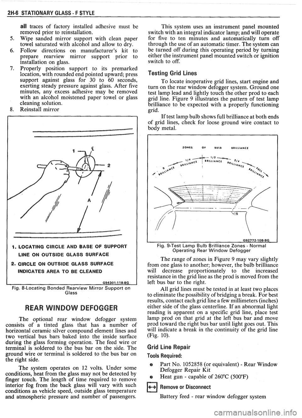
4. LOCATING CIRCLE AND BASE OF SUPPORT
LINE ON OUTSIDE GLASS SURFACE
2. CIRCLE ON OUTSIDE GLASS SURFACE
INDICATES AREA TO BE CLEANED
G94301-11 B.BG
Fig. 8-Locating Bonded earv view Mirror Support on
Glass
REAR WlMBOW DEFOGGER
The optional rear window defogger system
consists of a tinted glass that has a number of
horizontal ceramic silver compound element lines and
two vertical bus bars baked into the inside surface
during the glass forming operation. The feed wire or
terminal is soldered to the bus bar on the side. The
ground wire or terminal is soldered to the bus bar on
the right side.
The system operates on 12 volts. Under some
conditions, heat from the glass may not be detected by
finger touch. The length of time required to remove
interior fog from the back glass will vary with such
conditions as vehicle speed, outside glass temperature
and atmospheric pressure and number of passengers. This
system uses an instrument panel mounted
switch with an integral indicator lamp; and will operate
for five to ten minutes and automatically turn off
through the use of an automatic timer. The system can
be turned off during this operating period by turning
either the instrument panel mounted switch or ignition
switch to off.
Testing Grid Lines
To locate inoperative grid lines, start engine and
turn on the rear window defogger system. Ground one
test lamp lead and lightly touch the other prod to each
grid line. Figure
9 illustrates the pattern of test lamp
brilliance to be expected with a properly functioning
grid.
If test lamp bulb shows full brilliance at both ends
of grid lines, check for loose ground wire contact to
body metal.
Fig. 9-Test Lamp Bulb Brilliance Zones - Normal
Operating Rear Window Defogger
The range of zones in Figure 9 may vary slightly
from one glass to another; however, the bulb brilliance
will decrease proportionately to the increased
resistance in the grid line as the prod is moved from the
left bus bar to the right.
All grid lines must be tested in at least two places
to eliminate the possibility of bridging a break. For best
results, contact each grid line a few millimeters (inches)
either side of the glass centerline. If an abnormal light
reading is apparent on a specific grid line, place test
lamp prod on that grid at the left bus bar and move
prod toward the right bus bar until light goes out. This
will indicate a break in the continuity of the grid line
(Fig.
10).
Grid Line Repair
Tools Required:
o Part No. 1052858 (or equivalent) - Rear Window
Defogger Repair Kit
e Heat gun - capable of 260°C (500°F)
Remove or Disconnect
Battery 'feed - rear window defogger system
Page 1817 of 1825
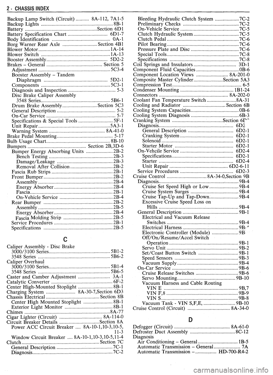
2 - CHASSIS INDEX
Backup Lamp Switch (Circuit) .......... 8A- 1 12. 7A 1-5
Backup Lights
..................................................... 8B-1
...................................................... Battery Section 6D 1
............................ Battery Specification Chart 6D 1-7
.................................... Body Identification ... .... OA- 1
Borg Warner Rear Axle .......................... Section 4B1
...................................................... Blower Motor 1A-14
Blower Switch
.................................................... 1 A- 13
Booster Assembly
............................................. 5D2-2
Brakes
- General ......................................... Section 5
Adjustment
.................................................... 5C3-4
Booster Assembly
. Tandem
Diaphragm
................... .... ..................... 5D2- 1
................................................ Components 5C3- 1
Diagnosis and Inspection
................................. 5-3
Disc Brake Caliper Assembly
.................................................... 3548 Series 5B6-1
Drum Brake Assembly ........................ Section 5C3
General Description
.......................................... 5-2
On-Car Service
.................................................... 5-7
Specifications & Special Tools ......................... .5 F. 1
...................................................... Unit Repair 5A3- 1
.......................................... Warning System 8A-4 1-0
............ Brake Pedal Mounting .. ......................... 5-1 7
Bulb Usage Chart
............................................ 8B-10
............................................ Bumpers Section 2B,3 D.6
Bumper Energy Absorbing Units
.................... 2B-2
Bench Testing
................................................ 2B-3
........................................ Damage/Leakage 2B-3
................................ Removal After Collision 2B-2
............................................. Fascia Rub Strips .2 B. 1
.................................................... Front Bumper 2B-2
Assembly
........................................................ 2B-4
Energy Absorber
........................................... 2B-4
............................................................. Fascia .2 B. 1
On-Vehicle Service
...................................... 2B-4
Rear Bumper
.................................... .... ............ 2B-2
........................................................ Assembly 2B-5
Energy Absorber
............................................ 2B-4
............. .................... Fascia Molding Strip .. 2B-5 ........................................... Service Procedures .2 B. 1
.................................................. Specifications 2B-5
C
Caliper Assembly . Disc Brake
.............................................. 3000/3 100 Series 5B 1-2
3548 Series
...................................................... 5B6-2
Caliper Overhaul
....................... 3000/3 100 Series .. ............... 5B 1-4
3548 Series
.................................................... 5B6-5
Caster and Camber Adjustment
........................ 3A- 1
............................................. Catalytic Converter 6F-2
Center High-Mounted Stoplight
....................... ... 8B- 1
Charging System
...................... 8A.30.7, Section 6D3
Chassis Electrical
.................................... Section 8B
Center High Mounted Stoplight
...................... 8B-1 ................................. Exterior Light Monitor .8 B. 1
................................................................ Chimes 8A-77
................................ Cigar Lighter (Circuit) 8A- 1
14-0
.............................. Circuit Breaker Details Section 8A
Power ACC Circuit Breaker .... 8A- 10.1.10.3.10.5.
11-3
.... Window Circuit Breaker 8A~10~1,10~3.10~5.1 1.4
Clutch
........................................................ Section 7C
......................................... General Description .7 C. 1 ........................................................... Diagnosis 7C-2 Bleeding
Hydraulic Clutch System
................. .7 C.2
Preliminary Checks ..................................... ... 7C-2
On-Vehicle Service
........................................... 7C-5
Clutch Hydraulic System
.................................. 7C-5
Clutch Pedal ...................................................... 7C-6
Pilot Bearing
..................................................... 7C-6
Pressure Plate and Disc
.................................... 7C-6
Special Tools
......................... ....... ................ 7C-8
Specifications
................................................... 7C-8
Coil Springs and Insulators .............................. 3D-1
Component Fluid Capacities
................................ OB-6
Component Location Views
........................ 8A-201-0
Composite Master Cylinder
................... Section 5A3
Compression Test
.................. .. ............................. 6-5
Condenser Mounting
....................................... 1B 1-24
Connectors
.................................................... 8A-202-0
Coolant Fan Temperature Switch
...................... 8A-3 1
Cooling and Radiator
................................ Section 6B
Cooling System Capacities
................................. OB-6
Cooling System Diagnosis
.................................... 6B-3
Cranking System
...................................... Section 6P*
Diagnosis ..................................................... 6~2
General Description ................................ 6D2- 1
Cranking System
........................................ 6D2- 1
Solenoid
................................................... 6D2- 1
Starter Motor ......................................... 6D2-1
On-Vehcile Service
...................................... 6D2-4
Specifications
............................................ 6D2- 1
Starter
........................................................ 6D2-4
Unit Repair
............................................ 6D2-6- 11
Service Procedures
...................................... 6D2-3
Cruise Control
.............................. 8A-34-0, Section 9B
Diagnosis
............................................................ 9B-4
Cruise Set Speed High or Low
.................... 9B-4
Cruise System Surges
.................................. 9B-4
Cruise Tap-Up and Tap-Down
...................... 9B-4
Excessive Cruise Speed Loss on
Hills
........................................................... 9B-4
General Description
........................................ 9B-1
Electrical and Vacuum Release
Switches
...................................................... 9B-4
Electrical Harness
.......................................... 9B-A
Electronic Controller (Module) .................... 9B .
Off/On/Resume/Accel Switch
Operation
.................................................. .91 B-
Servo Unit
.................................................... 9B-2
Set/Coast Button Switch .............................. 9B-1
................................................ Speed Sensors 9B-3
Vacuum Supply
............................................ 9B-4
On-Car Service
.................................................. 9B-6
................................ Cruise Release Switches 9B-6
.......................................... Servo Mounting 9B-10
Vacuum Harness and Cable Routing
VIN
E ................................. .. .................. 9B,7
.................................................... VIN F, 8 9B-9
....................................................... VIN S 9B-8
........................ Vacuum Tank - VIN S,F,E, 9B-10
.............................. Cruise Control (Circuit) 8A-34-0
D
......................................... Defogger (Circuit) $A-6 1-0
..................... ...... Defroster Duct Assembly ... .812 C-
Diagnosis
Air Conditioning
- General ........................... 1B-5
.................... Automatic Transmission - General 7A
Automatic Transmission
- ................ HD-700-R4-2