battery location PONTIAC FIERO 1988 Service User Guide
[x] Cancel search | Manufacturer: PONTIAC, Model Year: 1988, Model line: FIERO, Model: PONTIAC FIERO 1988Pages: 1825, PDF Size: 99.44 MB
Page 501 of 1825
6EZ-A-10 5.0L (VIN E) DRIVEABILITY AND EMISSIONS
TO OIL PRESS. SW.
&FUEL PUMP RELAY
BATTERY
12 V
. . . . . . . . FUSIBLE LINK 15 WAY
439 PNWBLK
419
BRNNVHT
SERIAL DATA
451
WHTIBLK
450 BLWHT
ALDL CONNECTOR
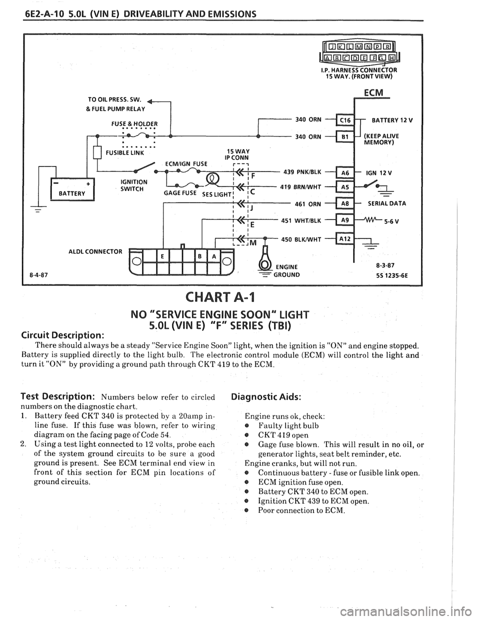
NO "SERVICE ENGINE SOON" "LIGHT
5.OL (VIN E) "F'" SERIES (TBI)
Circuit Description:
There should always be a steady "Service Engine Soon" light, when the ignition is "ON" and engine stopped.
Battery is supplied directly to the light bulb.
The electronic control module (ECM) will control the light and
turn it "ON" by providing a ground path through CKT 419 to the ECM.
Test Description: Numbers below refer to circled
numbers on the diagnostic chart.
1. Battery feed CKT 340 is protected by a
20amp in-
line fuse. If this fuse was blown, refer to wiring
diagram on the facing page of Code 54.
2. Using a test light connected to 12 volts, probe each
of the system ground circuits to be sure
a good
ground is present. See ECM terminal end view in
front of this section for ECM pin locations of
ground circuits.
Diagnostic Aids:
Engine runs ok, check:
@ Faulty light bulb
@ CKT419open
@ Gage fuse blown. This will result in no oil, or
generator lights, seat belt reminder, etc.
Engine cranks, but will not run.
@ Continuous battery - fuse or fusible link open.
@ ECM ignition fuse open.
@ Battery CKT 340 to ECM open.
o Ignition CKT 439 to ECM open.
@ Poor connection to ECM.
Page 642 of 1825
SECTION PAGE
A
Acceleration Mode .................... C2-2
AIC Request Signal
General Description
................. C1-4
Diagnosis ......................... C1-5
Air Injection Check Valve C6-3
Air Injection Control (Pedes) Valve
........ C6-3
Air
lnjection Reaction (A.I.R.) System
General Description
.................. C6- 1
Diagnosis ......................... C6-2
Part Information
.................... C6-4
Air Management Check (Pedes)
.......... C6-6
Air Pump
............................ C6-2
........................... Service C6-3
ALDL Connector ....................... A-1 2
Automatic Transmission Converter Clutch
(TCC) Electrical Diagnosis
.............. C8-4
C8-6
B
Backfire ............................ 6-6
......... Battery Voltage Correction Mode C2-2
Before
Start~ng ...................... B-1
C
Cal Pak General
Descript~on ................. C1-2
Service
........................... C1-8
Canister Control Valve
................. C3-2
Canister Hoses
....................... C3-3
Canister Purge Solenoid
................ C3-3
Canister Purge Valve Check
............. C3-6
Chart A-
I :
No Service Engine Soon Light .......... A-10
Chart A-2:
No ALDL Data. Or Won't Flash Code 12.
Or Service Engine Soon Light On Steady
. . A-1 2
Chart A-3:
Engine Cranks But Won't Run
.......... A-14
Chart A-7:
Fuel System Diagnosis
................ A-1 8
Chart
B-1:
Restricted Exhaust System Check ........ 6-7
Chart C-IA:
ParkINeutral Switch Diagnosis ......... Cl-12
Chart C-16:
Crank Signal
....................... C1-14
Chart C-1 D
.................. MAP Output Check C1-16
SECTION
Chart C-2C:
Idle Air Control (IAC) System Check ...... C2-18
Chart C-3:
Canister Purge Valve Check
........... C3-6
Chart C-4B:
Ignition System Check
................ C4-4
Chart C-5:
Electronic Spark Control
(ESC) .......... C5-4
Chart C-66:
Air Management Check
.............. C6-6
Chart C-7:
Exhaust Gas Recirculation
............. C7-4
Chart
C-$A:
Transmission Converter Clutch (TCC) .... C8-4
Chart
C-8A
700-4R Transmission Electrical Diagnosis . . C8-6
Chart
C-86:
Shift Light ......................... C8-8
Chuggle
............................ B-3
Clear Flood Mode
..................... C2-2
Closed Loop
......................... C2-2
Code12
............................ C4-2
Code13
............................ A-22
Code14
............................ A-24
Code43
............................ A-42
Code44
............................ A-44
Code45
............................ A-46
Code54
............................ A-48
Codes 5 1.52. 55
...................... A-50
Component Location
.................. A-2
Control Valves
....................... C3-3
Coolant Temperature Sensor
General Description
.................. C1-2
Diagnosis
.......................... Cl-5
Service
........................... C1-8
Cuts Out ............................ 6-4
Crank Signal General Description
................. C1-4
Diagnosis
......................... C1-14
D
Deceleration Mode .................... C2-2
Page 663 of 1825
6E3-A-"I 2.8L (VlN S) DRIVEABILITY AND EMlSSlONS
TO OIL PRESS. SW.
&FUEL PUMP RELAY
FUSE
81 HOLDER BATTERY 12 V .. m.. . n.
. . . . . . . . FUSIBLE LINK
439 PNWBLK
419 BRNNVHT
SERIAL
DATA
451
WHTJBLK
450 BLKNVHT
ALDL CONNECTOR
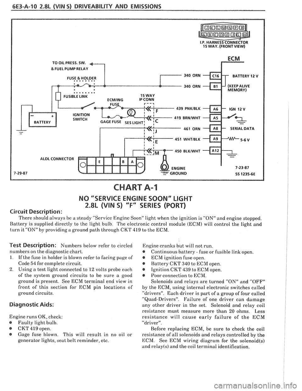
NO "SERVICE ENGlNE SOON" "LIGHT
2.8b (VIM 5) 'T" "SERIES (PORT)
Circuit Description:
There should always be a steady "Service Engine Soon" light when the ignition is "ON" and engine stopped.
Battery is supplied directly to the light bulb. The electronic control module
(ECNI) will control the light and
turn it "ON" by providing a ground path through CKT 419 to the ECM.
Test Description: Numbers below refer to circled
numbers on the diagnostic chart.
1. If the fuse in holder is blown refer to facing page of
Code
54 for complete circuit.
2. Using a test light connected to 12 volts probe each
of the system ground circuits to be sure a good
ground is present. See ECM terminal end view in
front of this section for
ECM pin locations of
ground circuits.
Diagnostic Aids:
Engine runs OK, check:
@ Faulty light bulb.
@ CKT 419 open.
@ Gage fuse blown.
This will result in no oil or
generator lights, seat belt reminder, etc. Engine
cranks but will not run.
@ Continuous battery - fuse or fusible link open.
@ ECM ignition fuse open.
@ Battery CKT 340 to ECM open.
@ Ignition CKT 439 to ECM open.
e Poor connection to ECM.
Solenoids and relays are turned "ON"
and "OFF"
by the ECM, using internal electronic switches called
"drivers". Each driver is part of a group of four called
"Quad-Drivers". Failure of one driver can damage
any other driver in the set. Solenoid and relay coil
resistance must measure more than 20 ohms. Less
resistance will cause early failure of the ECM
"driver".
Before replacing ECM, be sure to check the coil
resistance of all solenoids and relays controlled by the
ECM. See ECM wiring diagram for the
solenoid(s)
and relay(s) and the coil terminal identification.
Page 726 of 1825
DRIVEABILITY AND EMISSIONS 2.8L (VIN S) 6E3-C1-7
REFERENCE END
PROM PROM CARRIER
4S 81165-6E
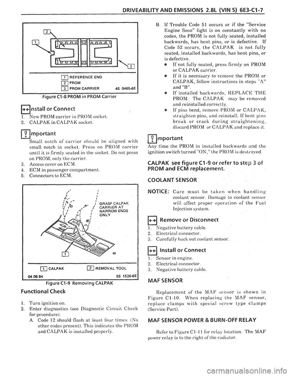
Figure C1-8 PROM in PROM Carrier
mnstall or Connect
1. New PROM carrier in PROM socliet.
2. CALPAK in CALPAK socket.
mmportant
Small notch of carrier shoiild he aligned with
small notch in socket. Press on PROM carrier
until it is firmly seated in the socket. Do not press
on PROM; only the carrier.
3. Access cover on ECM.
4. ECRil in passenger compartment.
5. Connectors to ECM.
b A,' I
;,* fd I
: GRASP CALPAK 1% ,/w 1' CARRIERAT
[ZJ REMOVAL TOOL
Figure C1-9 Removing CALPAK
B. If Trouble Code 51 occurs or if the "Service
Engine Soon" light is on constantly with no
codes, the PROM is not fully seated, installed
backwards, has bent pins, or is defective. If
Code
52 occurs, the CALPAK is not fully
seated, installed backwards, has bent pins, or
is defective.
If not fully seated,
press firmly on PROM
or CALPAK carrier
a, If it is necessary to remove the PROM or
CALPAK, follow instructions in steps "A"
and
"B".
@ If installed backwards, REPLACE THE
PROM. The CALPAK may be removed
and reinstalled correctly.
@ If pins bend, remove PROM or CALPAK,
straighten pins, and reinstall. If
bent pins
break or crack during
straightening,
discard PROM or CtILPAK and replace it,.
am port ant
Any time the PROM in installed backwards and the
ignition switch turned
"ON," the f'I
PROM and ECM replacement.
COOLANT SENSOR
NOTICE:
Care must be taken when handling
coolant sensor.
Damage to coolant sensor
will affect proper operation of the Fuel
Injection
system.
B Remove or Disconnect
1. Negative buttery cable.
2.
Electricril connector.
3. Carefully back out coolant sensor.
a ln,aIl
1. Sensor in
or Connect
engine.
2. Electrical connector.
3. Negative battery cable.
MAF SENSOR
Functional Check
Replacement of the iL'IAF xcnsor is shown in
Figure C1-10. When
replacing the MAF sensor,
1. Turn ignition on.
replace cla~llps with special hcrew type cla~rlps
2. Enter diagnostics (see Diagnostic Circuit Check (Service Part).
for procedure).
A. Code 12 should flash at least four times. (Yo MAF SENSOR POWER & BURN-OFF RELAY
other codes present). This indicates the PIIOM
and CALPAK is installed properly.
Refer to Figure C 1- 1 1 for relay location. 'rhe MAF
power relay is to the right ofthe radiator
Page 813 of 1825
TO MAF SENSOR
POWER & BURN-OFF
RELAY, OIL PRESS. SW.
.....-
439 PNKIBLK
419 BRNNVHT
SERIAL DATA
451 WHTIBLK
450
BLWHT
ALDL CONNECTOR
CHART A - 1
NO "'SERVICE ENGINE SOON" LIGHT
5.OL (VIN F) & 5.7L (VIN 8) "F'XSEBIE'S (PORT)
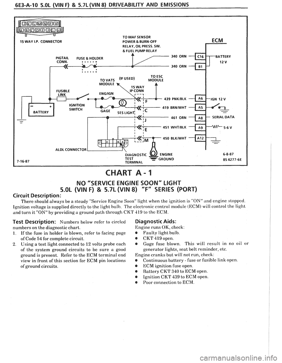
Circuit Description:
There should always be a steady "Service Engine Soon" light when the ignition is "ON" and engine stoppccl.
Ignition voltage is supplied directly to the light bulb. The electronic control module (ECM) will control the light
and turn it
"ON" by providing a ground path through CKT 419 to the ECM.
Test Description: Numbers below refer to circled
numbers on the diagnostic chart.
1. If the fuse in holder is blown, refer to facing page
of Code
54 for complete circuit.
2. Using a test light connected to 12 volts probe each
of the system ground circuits to be sure a good
ground is present. Refer to the ECM terminal end
view in front of this section for ECM pin locations
of ground circuits.
Diagnostic Aids:
Engine runs OK, check:
r Faulty light bulb.
@ CKrI' 419 open.
@ Gage fuse blown. This
will result in no oil or
generator lights, seat belt reminder, etc.
Engine cranks but will not run, check:
r Continuous battery - fuse or fusible link open.
@ ECM ignition fuse open.
r Battery CKT 340 to ECM open.
@ Ignition CKT 439 to ECM open.
@ Poor connection to ECM.
Page 881 of 1825

6E3-C9-6 5.OL (VIN F) & 5.7L (VIN 8) DRIVEABILIW AND EMISSIONS
INSTRUMENT PANEL 1
MODULE ASM ECM (PFI)
BRACKET
a BOLTISCREW (4)
1 BOLTISCREW (2) 4.7-7.0 N.m (3.3-5.1 LBS. FT.)
1 BOLTISCREW RETAINER (2)
NUT (4) 4.7-7.0 N.m (3.3-5.1 LBS. FT.)
SPACER
I 1 COVER ECM 8s 4667-6E 1
Figure C1-7 - ECM LOCATION
Figure
C1-8 - MemICal Unit Socket
Please do not record on ECM cover. This will
allow positive identification of ECM parts
throughout the service life of the vehicle.
Important
'I'o prevent internal ECM damage, the ignition
must be "OFF", when
disconnecting or
reconnecting power to ECM (for example, battery
cable, ECM pigtail, ECM fuse, jumper cables,
etc.).
PUSH
Figure C1-9 - MernICal Unit Installation
ECM OR MEM-CAL REPLACEMENT
FIGURE
C1-7
Remove or Disconnect
1. Negative battery cable.
2. Right hand hush panel.
3. Connectors from ECM.
4. ECM mounting hardware.
5. ECM from passenger compartment.
6. ECM access cover. (Figure C1-1).
7. Mem-Cal removal. (Figure C1-8).
lmportant
Replacement ECM is supplied without a Mem-Cal,
so care should be used when removing it from the
defective ECM because it will be reused
in the new
ECM.
Using two fingers, push both retaining clips back
away from the Mem-Cal. At the
same time, grasp it at
both ends and lift it up out of the socket. Do not
remove the cover of the Mem-Cal.
Use of unapproved
Mem-Cal removal methods may cause damage to the
Mem-Cal or socket.
Inspect
For alignment notches of the Mem-Cal and
carefully set it aside. Do not open the
Mern-Cal.
IF ECM IS BEING REPLACED:
Remove or Disconnect
1. New ECM from its packaging and check the - -
service number to make sure it is the same as the
defective ECM.
2. Access Cover.
Page 883 of 1825

6E3-C1-8 5.OL (VIN F) & 5.7L (VIN 8) DRIVEABILITY AND EMISSIONS
MAF SENSOR Install or Connect
Replacement of the MAF sensor is shown in
Figure C1-10.
MAF SENSOR POWER &
BURN-OFF RELAY
Refer to Figure C1-11 for relay location
OXYGEN SENSOR
(Figure
C1-12)
NOTICE: The oxygen sensor uses a permanently
attached pigtail and connector. This
pigtail should not be removed
from the
oxygen sensor. Damage or removal of the
pigtail or connector could affect proper
operation of the oxygen sensor.
Important
Take care when handling the oxygen sensor. The
in-line electrical connector and louvered end must
be kept free of grease, dirt, or other contaminants.
Also, avoid using cleaning solvents of any type.
Do not drop or roughly handle the oxygen sensor.
Remove or Disconnect
The oxygen sensor may be difficult to remove
when engine temperature is below 48°C (120°F).
Excessive force may damage threads in exhaust
manifold or exhaust pipe.
1. Negative battery cable.
2. Electrical connector.
3. Carefully
back out oxygen sensor.
OXYGEN SENSOR 38-46 N.rn (28-33 LBS. FT.)
Figure C1-12 - 0, Sensor
Important
A special anti-seize compound is used on the
oxygen sensor threads. The compound consists of
a
liquid graphite and glass beads. The graphite will
burn away, but the glass beads will remain,
making the sensor easier to remove.
New, or service, sensors will already have the
compound applied to the threads. If a sensor is
removed from an engine, and, if for any reason it is
to be reinstalled, the threads must have anti-seize
compound applied before reinstallation.
1. Coat threads of oxygen sensor with anti-seize
compound
PIN 5613695, or equivalent, if
necessary.
2. Sensor, and torque to 41 N*m (30 ft. lbs.).
3. Electrical connector.
4. Negative battery cable.
THROTTLE POSITION SENSOR (TPS)
Remove or Disconnect
1 Electrical connector.
2. Two TPS attaching screws and retainers.
3. Sensor.
Install or Connect
1. With throttle valve in the normal closed idle
position, install throttle position sensor on throttle
body assembly, making sure TPS
picltup lever
lines up with tang on throttle actuator lever. (See
Figure
C1-13)
2. Retainers and two TPS screws. DO NOT tighten
screws until TPS is adjusted.
10 THROTTLE BODY ASSEMBLY
20 THROTTLE POSITION SENSOR (TPS)
21 TPS ATTACHING SCREW
Figure
C1-13 - Throttle Position Sensor Service
Page 894 of 1825
DRIVEABILITY AND EMISSIONS 5.OL (VIN F) & 5.7L (VIN 8) 6E3-C2-7
Figure C2-8 Fuel Rail Pressure Regulator
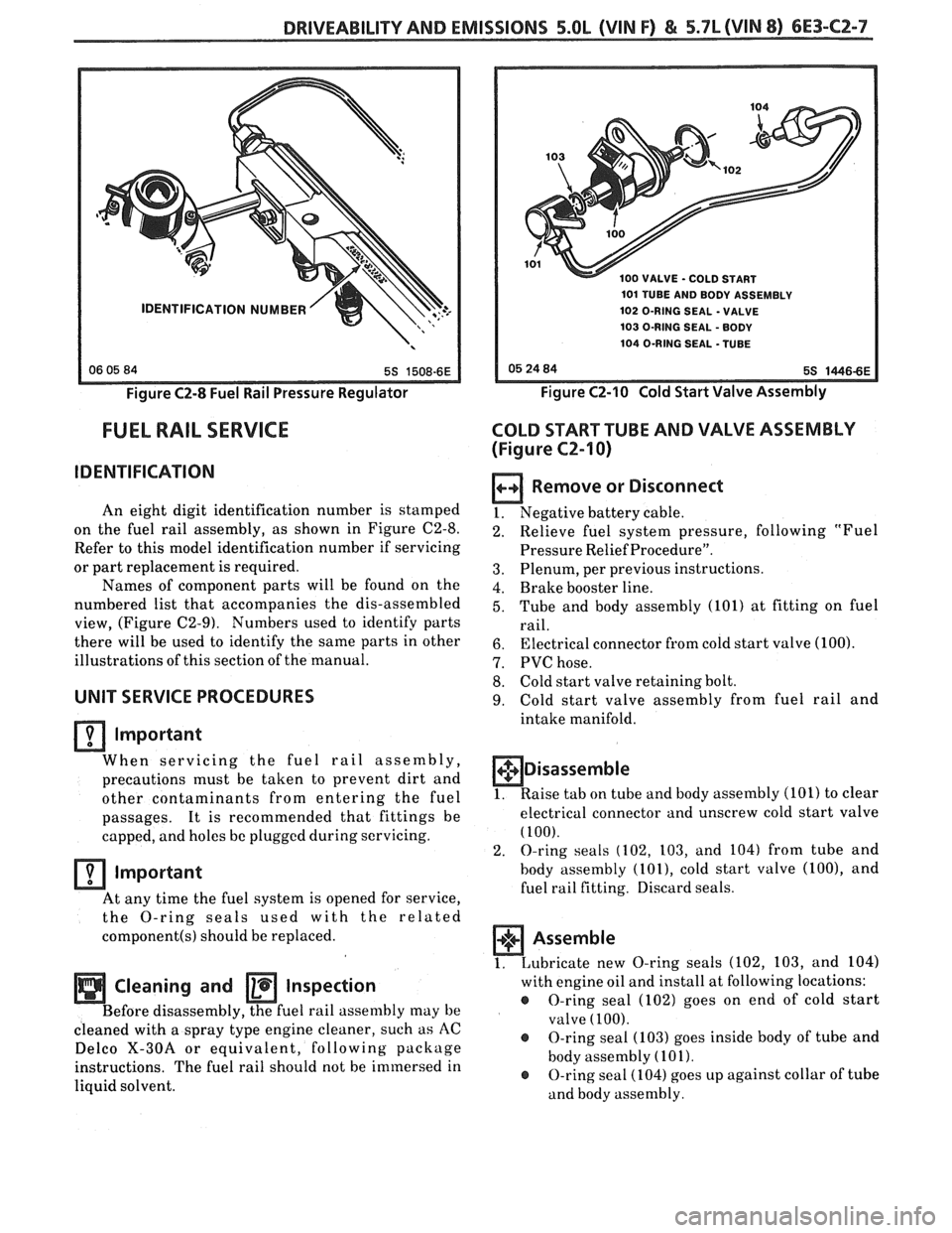
FUEL RAIL SERVICE
IDENTIFICATION
An eight digit identification number is stamped
on the fuel rail assembly, as shown in Figure C2-8.
Refer to this model identification number if servicing
or part replacement is required.
Names of component parts will be found on the
numbered list that accompanies the dis-assembled
view, (Figure C2-9). Numbers used to identify parts
there will be used to identify the same parts in other
illustrations of this section of the manual.
UNIT SERVICE PROCEDURES
lrnportant
When servicing the fuel rail assembly,
precautions must be taken to prevent dirt and
other contaminants from entering the fuel
passages. It is recommended that fittings be
capped, and holes
be plugged during servicing.
Important
At any time the fuel system is opened for service,
the
O-ring seals ised with the related
component(s) should be replaced.
Cleaning and Inspection
Before disassembly, the fuel rail assenlbly may be
cleaned with a spray type engine cleaner, such as
AC
Delco X-30A or equivalent, following
package
instructions. The fuel rail should not be immersed in
liquid solvent.
0 VALVE - COLD START
101 TUBE AND BODY ASSEMBLY
102 O-RING SEAL
- VALVE
103 O-RING SEAL
- BODY
104 O-RING SEAL -TUBE
Figure CZ-10 Cold Start Valve Assembly
COLD START TUBE AND VALVE ASSEMBLY
(Figure
CZ-I 0)
Remove or Disconnect
1. Negative battery cable. -
Relieve fuel system pressure, following "Fuel
Pressure Relief Procedure".
Plenum, per previous instructions.
Brake booster line.
Tube and body assembly (101) at fitting on fuel
rail.
Electrical connector from cold start valve (100).
PVC hose.
Cold start valve retaining bolt.
Cold start valve assembly from fuel rail and
intake manifold.
+$ Disassemble
1. Raise tab on tube and body assembly (101) to clear
electrical connector and unscrew cold start valve
(100).
2. O-ring seals (102, 103, and 104) from tube and
body assembly
(lOl), cold start valve (loo), and
fuel rail fitting. Discard seals.
1. Lubricate
new O-ring seals (102, 103, and 104)
with engine oil and install at following locations:
@ O-ring seal (102) goes on end of cold start
valve
(100).
@ O-ring seal (103) goes inside body of tube and
body assembly
(101).
@ O-ring seal (104) goes up against collar of tube
and body assembly.
Page 958 of 1825
INDEX
SECTION PAGE
.................... Acceleration Mode C2-2
A/C On Signal
General Description
................. C1-4
......................... Diagnosis C1-5
Air Injection Check Valve
............... C6-4
Air Injection Control (Pedes) Valve
........ C6-1
Air Injection Reaction (A.I.R.) System
General Description
................. C6-1
......................... Diagnosis C6-2
Air Management Check (Pedes)
.......... C6-6
AirPump ........................... C6-2
........................... Service C6-3
...................... ALDL Connector A- 12
Automatic Transmission
Overdrive Switch Adjustment
.......... C8-3
Automatic Transmission Converter Clutch
(TCC) Electrical Diagnosis
.............. C8-6
Backfire
............................ B-5
Battery Voltage Correction Mode
......... C2-3
....................... Before Starting B-I
........................ Burnoff Relay C1-8
......................... Calpac Error 8-60
........................ Canister Hose C3-3
Canister Purge Solenoid
................ C3-3
Chart
A-1 :
.......... No Service Engine Soon Light A-1
0
Chart
A-2:
No ALDL Data. Or Won't Flash Code 12.
Or Service Engine Soon Light On Steady
. . A-1 2
Chart A-3:
Engine Cranks But Won't Run
.......... A-14
Chart A-7:
................ Fuel System Diagnosis A- 18
Chart A-9:
........... Cold Start Valve Circuit Test A-22
Chart
B-1:
Restricted Exhaust System Check ........ B-8
Chart
C-1A:
......... ParkINeutral Switch Diagnosis C1-10
Chart C-2A:
................. Injector Balance Test C2-18
Chart C-2C:
Idle Air Control (IAC) System Check ...... C2-20
SECTION PACE
Chart C-3:
........... Canister Purge Valve Check C3-4
Chart C-4:
................ Ignition System Check C4-4
Chart
6-5:
.......... Electronic Spark Control (ESC) C5-4
Chart C-6:
.............. Air Management Check C6-6
Chart C-7:
Exhaust Gas Recirculation
............. C7-4
Chart
C-8A:
Automatic Transmission Converter Clutch
............................. (TCC) C8-6
Chart C-8B:
Manual Transmission With Overdrive
.... C8-10
Chart C- 12
:
................. Cooling Fan Control C12-2
............................ Chuggle B-3
................... Clear Flood Mode.. C2-2
......................... Closed Loop C2-1
Code12
............................ C4-1
Code13
............................ A-24
Code14
............................ A-26
Code15
............................ A-28
Code21
............................ A-30
Code22
............................ A-32
Code23
............................ A-34
Code24
............................ A-36
Code25
............................ A-38
Code32
............................ A-40
Code33
............................ A-42
Code34
............................ A-44
Code36
............................ A-46
Code41
............................ A-48
Code42
............................ A-50 C4-2
Code43
............................ A-52
Code44
............................ A-54
Code45
............................ A-56
Code46
............................ A-58
Code54
............................ A-60
...................... Codes 51.52. 53 A-62
Cold Start Tube And Valve Assembly
...... C2-7
Cold Start Fuel
lnjection Sw~tch
.................. General Description C2-11
......................... Diagnosis A-22
.................. Component Location A-2
Coolant Temperature Sensor
.................. General Description C1-2
.......................... Diagnosis C1-4
A-26
........................... Service C1-7
Page 1122 of 1825

AUTOMATIC TMNSMISSION ON-VEHICLE SERVICE 7A1-3
e Propeller shaft oil seal worn or damaged
o Governor cover
e Line pressure pipe plug loose
@ Porous casting
3. Leak at converter end:
Converter seal damaged
- Seal lip cut. (Check converter hub for
damage.)
- Bushing moved forward and damaged
- Garter spring missing from seal
o Converter leak in weld area. (Refer to
Torque Converter.)
Porous casting (Case or pump)
4. Fluid comes out vent pipe or fill tube:
Over-filled
Water or coolant in fluid. Fluid will appear
milky.
e Case porous
e Incorrect fluid level indicator
e Plugged vent
e Drain back holes plugged
Mispositioned oil pump to case gasket (if
equipped)
Case Porosity Repair
1. Clean the leak area with solvent and air dry.
CAUTION: Epoxy adhesive may cause
skin irritations and eye damage. Read
and follow all information on the
container label as provided by the
manufacturer.
2. Mix a sufficient amount of epoxy adhesive,
# 1052533, or equivalent, following the
manufacturer's recommendations.
3. While the transmission case is hot, apply epoxy
adhesive with a clean, dry soldering acid brush.
4. Allow the epoxy adhesive to cure for three hours
before starting the engine.
5. Repeat fluid leak diagnosis procedures.
TORQUE CONVERTER CLUTCH ELECTRICAL
CONTROLS
The Torque Converter Clutch (TCC) system uses
controls that are internal as well as external to the
transmission. For internal control components of the
TCC system, refer to the I-Iydraulic Diagnosis Section
for for wiring diagrams and switch locations.
The external control components of the TCC
system include:
1. Brake Release Switch - To avoid stalling the
engine when braking, the converter clutch is
released any time the brakes are applied.
2. Electronic Control ModuOe - Receives input
signals and grounds TCC solenoid to apply clutch
when proper operating conditions are met.
3. Throttle Position Sensor - Sends throttle
position information to Electronic Control
Module.
4. Vacuum Sensor - Sends engine vacuum (load)
information to Electronic Control Module.
5. Vehicie Speed Sensor - Sends vehicle speed
information to Electronic Control Module.
6. Coolant Temperature Sensor - Sends engine
coolant temperature information to Electronic
Control Module.
TORQUE CONVERTER CLUTCH DIAGNOSIS
To properly diagnose the Torque Converter
Clutch (TCC) system perform all electrical testing first
and then the hydraulic testing. Refer to the appropriate
Driveability and Emissions Section (6E) for additional
Torque Converter Clutch Information
ON-VEHICLE SERVICE
SI-IIFT CONTROL CABLE
Remove or Disconnect (Fig. 1)
1. Negative battery cable.
2. Raise car, see Section OA.
3. Cable attachments at transmission.
4. Lower car.
5. Console, see Section
8C.
6. Cable at control lever and base.
7. Cable from floor.
install or Connect
1. Cable to floor.
2. Cable at base and control lever.
3. Console, see Section 8C.
4. Place control lever in "NEUTRAL"
5. Raise car.
6. Cable attachments at transmission.
7. Adjust cable.
8. Lower car.
9. Negative battery cable.
Adjust (Fig. 1)
1. Place control lever in "N" (Neutral).
2. Raise car, see Section 0.4.
3. Loosen cable
attachment at shift lever.
4. Rotate shift lever "clockwise" to park detent and
then back to neutral.
5. Tighten cable attachment.
15
N-m (11 lbs. ft.)
Important
Levg must be held out of "PARK" when
torquing nut.
6. Lower car.
7. Check cable adjustment by rotating control lever
thru the detents.
Remove or Disconnect (Fig. 2)
1. Negative battery cable.
2. Console, see Section 8C.
3. Cable at control lever and base.