reset PONTIAC FIERO 1988 Service Owner's Guide
[x] Cancel search | Manufacturer: PONTIAC, Model Year: 1988, Model line: FIERO, Model: PONTIAC FIERO 1988Pages: 1825, PDF Size: 99.44 MB
Page 1613 of 1825
842-2 INSTRUMENT PANEL. GAGES & CONSOLE
Pinion Gear
The PINION GEAR is attached to the
traaasmission/transaxle output shaft and rotates in
proportion to the speed of the car. This rotation is
transferred from the pinion gear to the speedometer
head by the speedometer cable.
Photo Speed Sensor
On vehicles that use a mechanical drag-cup
speedometer, the PHOTO SPEED SENSOR is
inserted into the frame of the mechanical speedometer
to provide an electrical feedback to the ECM that
represents vehicle speed. The ECM needs to know how
fast the car is traveling in order to control and operate
the cruise control, cooling fan, and transmission and
evaporative systems.
The photo speed sensor is made up of two special
electronic devices: a Eight-Emitting Diode (LED) and
a photo transistor (a light-sensitive amplifying device).
In the mechanical speedometer, there is a reflective
blade attached to the rotating magnet that is polished
to
reflect light from the LED back to the photo
transistor. Whenever the light strikes the photo
transistor, it conducts electricity. The rate that the
transistor conducts and does not conduct is
proportional to the speed of the magnet, which reflects
the speed of the vehicle. This voltage signal from the
photo transistor is sent to a buffer amplifier (part of the
speed sensor) to be conditioned to a signal the ECM
can understand and use.
PM Generator
The PM (Permanent Magnet) GENERATOR is
a small
AC generator used to sense vehicle speed. The
shaft of the generator fits into a pinion gear in the
transmission/transaxle output shaft (as does the cable
in
a mechanical system).
When the output shaft rotates, the magnet rotates
and generates a voltage. Except for the permanent
magnet, the
PM Generator is exactly like a miniature
alternator. The PM generator is constructed to provide
a voltage whose frequency is about
1.1 cycles per
second for every mile per hour of vehicle speed. This
signal is sent to a buffer amplifier, and then to the
speedometer and the
EGM.
SPEEDOMETER
The speedometer is a road speed indicator with
an odometer to record total mileage, and, on some cars,
a resettable trip odometer.
The major types of speedometers in use are
mechanical instruments and electronic instruments.
Mechanical speedometers use a dial needle to indicate
road speed. Electronic speedometers include
instruments that use a dial indicator and those using
bar-graph
LCD's (Liquid Crystal Displays) or VTF
(Vacuum Tube Fluorescent) displays.
Meehanice! Speedometers
A mechanical speedometer uses a cable driven
(through a pinion gear) by the transmission output
shaft. The cable connects to a magnetic drag-cup inside the
speedometer, which rotates the speedometer
needle. The end of the rotating cable causes a small bar
magnet to rotate within a metal cup. As the magnet
rotates within the cup, it magnetically attracts (drags)
the metal cup along behind it. Two things work to
prevent the cup from rotating as quickly as the magnet.
1. The distance of the magnet from the cup reduces
its effect on the cup.
2. A counterspring is wound around the shaft of the
cup in such a way as to oppose the normal
rotation of the cup. The counterspring loads the
drag-cup to give correct indication of the speed,
prevent needle overshoot, and also to return the
drag cup to a zero point.
Mechanical speedometers require a photo speed
sensor to provide road speed information for the ECM
and other systems, such as Cruise Control and the TCC
(Torque Converter Clutch).
The odometer on these instruments consists of
numbered wheels that are rotated by the speedometer
cable through worm gears.
Quartz Speedometer
The quartz speedometer is an electrically driven
instrument. The indicator needle is driven by a
precision DC motor, and is countersprung to provide
a mechanical load, prevent overshoot of the needle, and
return the indicator to zero when the road speed is
zero.
The source of speed information for a quartz
speedometer is the PM generator. From the PM
generator, speed information goes to the buffer
amplifier to be converted to digital voltage, and then
to the cluster circuitry, which interprets the speed of
the vehicle and produces small voltage to apply to the
speedometer motor.
The odometer on this instrument consists of
numbered wheels that are electrically driven by a
special precision DC motor called a stepper motor.
Digital Speedometer
Digital clusters utilize two types of displays: LCD
(Liquid Crystal Display) and VTF (Vacuum Tube
Fluorescent). They are used in digital speedometers
and bar-graph tachometers, fuel gages, etc.
Speed information entering the cluster from the
buffer amplifier is interpreted by a microcomputer
which controls the speed indication, the tachometer
display and the odometer reading.
The odometers associated with these instruments
utilize either numbered wheels driven by a small motor
or electronic displays. With an electronic display, the
mileage reading is stored in a computer chip (called a
non-volatile RAM chip; NVRAM) that does not
become 'erased' when the vehicle is turned off,
as the
display does not retain the information.
FUEL GAGE
An electrical fuel gage is used on all models,
consisting of an instrument panel gage and a fuel tank
pick-up. The fuel gage indicates the quantity of fuel in
Page 1615 of 1825
8C.4 INSTRUMENT PANEL, GAGES & CONSOLE
ON-CAR SERVlCE
lNSTRUMEMT PANEL PAD
Figure 601
Remove or Disconnect
1. Four (4) screws in defroster ducts.
2. Screws
under lip of
I.P, pad.
3. I.P. pad from carrier.
lnstall or Connect
1. I.P. to carrier.
2. Screws
under lip of I.P. pad.
3. Four (4) screws in defroster ducts.
INSTRUMENT PANEL CLUSTER
Figure 683
Remove or Disconnect
1. Right and left lower trim plates. Removal of
lower I.P. covers not required.
2. Instrument cluster trim plate.
3. Six (6) cluster attachment screws, pull cluster
back and disconnect speedo cable and electrical
connections.
4. Trip odometer, reset knob (if so equipped) and
remove cluster lens.
5. Individual gages and/or speedo head are now
accessible for service or replacement. If service is
intended for only gages or tachometer, skip Step
3.
Install or Connect
1. Trip odometer, reset knob (if so equipped) and
remove cluster lens.
2. Six
(6) cluster attachment screws, pull cluster
back and disconnect speedo cable and electrical
connections.
3. Instrument cluster trim plate.
4. Right and left lower trim plates. Removal of
lower I.P. covers not required.
INSTRUMENT PANEL CARRIER
Figure 602
Remove or Disconnect
Negative battery cable.
Console. Instrument panel pad and lower hush panels.
Right and left lower I.P. covers and trim plates.
Instrument panel cluster and headlight switch.
Lower steering column.
Five (5) upper and six (6) lower I.P. carrier to
cowl screws.
Instrument panel electrical harness at cowl
(bulkhead) connector, and under dash.
I.P. carrier from car.
10. I.P. mounted components (A/C, defroster ducts,
wiring harness, etc.) are now accessible for service
or replacement.
11. Any seals or sealant damaged during
disassembly.
Install or Connect
I.P. carrier to car.
Instrument panel electrical harness at cowl
(bulkhead) connector, and under dash.
Five (5) upper and six (6) lower I.P. carrier to
cowl screws.
Steering column.
Instrument panel cluster and headlight switch.
Right and left lower I.P. covers and trim plates.
Instrument panel pad and lower hush panels.
Console.
Negative battery cable.
HEADLIGHT SWITCH
Figure 620
Remove or Disconnect
1. Right and left lower trim plates. Removal of
lower I.P.
cover(s) not required.
2. I.P. cluster trim plate.
3. Two (2) switch assembly retaining screws.
4. Depress side tangs and pull switch assembly from
I.P.
5. Individual switches of assembly are now
accessible for service or replacement.
Install or Connect
1. Depress side tangs and replace switch assembly
to I.P.
2. Two
(2) switch assembly retaining screws.
3. I.P. cluster trim plate.
4. Right and
left lower trim plates. Removal of
lower I.P.
cover(s) not required.
DASH MOUNTED ACCESSORY SWITCHES
Figure 62 1
Installation for various dash mounted accessory
switches is shown in Fig.
62 1.
CONSOLE MOUNTED SWITCHES AND
ACCESSORIES
Figure 6 17
Installation of various console mounted switches,
lights and accessories is shown in Figure 617.
CONSOLE
Remove or Disconnect
1. Negative battery cable.
2. Shift gate trim plate. Requires removal
of shift
handle and seven (7) screws.
3. Radio/A/C-heater controller trim plate.
Page 1650 of 1825
RADIO SYSTEMS AND ANTENNAS 9A-1
SECTION 9A
0 SYSTEMS AND ANTENNAS
CONTENTS
............................................. General Description .................................... 9A-1 Radio Operation 9A-4
Radio
............................................................ 9A-1 ETR AM/FM Stereo (UM-7) ....................... 9A-4
Antennas
........................................................ 9A- 1 ETR Stereo Cassette (UM-6) ......................... 9A-5
Fixed Antenna
.......................................... 9A- 1 ETR Stereo/Cassette/Eaualizer
Diagnosis ........................................................
Radio ....................... .. ................................
Static and Noise .................................... .....
........................................ Popping Noise
Preliminary Diagnostics
.............................
Antenna ................................. .. ................
Tape Player .................. .... .......................
Service Procedures ....................................
Radio and Speakers ........................... .............
Radio Noise Suppression Equipment ............
Stereo Cassette Tape Player ..........................
Tape & Tape Player Care ........................
(UX-1) ..................................................... 9A-6
Advanced ETR
Stereo/Cassette/Equalizer Touch
Control
.................................... ... .............. 9A-7
On-Car Service .............................................. 9A-9
Radio Receiver
............................................ 9A-9
Radio Steering Wheel Controls
..................... 9A-9
Audio Amplifier
........................................... 9A-9
Radio Suppression
..................................... 9A-9
Front Speaker
................................................. 9A-9
............... Rear Speaker; Sub Woofer Speaker
9A-9
Antenna
..................... .. ............................. 9A- 10
GENERAL DESCRIPUION
RADIO ANTENNAS
For radios and radio use see the "Radio Fixed Antenna
Operation" section. ETR means 'Electronically Tuned The
fixed antenna on the right front fender
Receiver'. cannot be adjusted up or down. It may provide
improved reception in rural areas.
- The fixed antenna is designed to withstand most
car washes without damage. If the antenna becomes
slightly bent, you can straighten it by hand. The
antenna can be replaced if severely bent (by vandalism,
etc.). Antennas must be kept clean for good
performance.
RADIO
Because radio problems are normally repaired at
authorized warranty repair stations, the tendency is to
remove the set when a problem is reported, without any
preliminary diagnosis. This results in a large number
of radios being "No Trouble Found" units when
received by the warranty repair stations. Often the
trouble can be corrected without radio removal. wire.
If equipped with
A/C, the blower motor has a
built-in capacitor. Extra electrical equipment added to
the static if not properly grounded or wiring was
improperly routed.
Weak
FM station reception will be affected by
nearby buildings, car speed and direction. These
"flutter" and "fading" conditions are characteristic of
weak FM signals.
ETR radios require clock and button reset if the
battery is disconnected.
Popping Noise
Static and Noise Operating devices such as turn signals, pushing in
cigarette lighter, operating stop lights, etc., may cause
Ground strap connections must be clean and
a popping noise on distant (weak) AM signals.
tight, spark plug cables must be TVRS type and in
good condition and resistance-type spark plugs used.
Preliminary Diagnostics
Capacitors are used in the generator, heating/air
conditioning system, and fuse panel to reduce noise
The inconvenience of driving without a radio
entering the radio through the feed wires. If the car has
while the set is being serviced can often be avoided if
a heater only, the capacitor is in the blower motor feed
the following quick checks are used to eliminate
Page 1654 of 1825
RADIO SYSEEMS AWlD ANTENNAS 9A-5
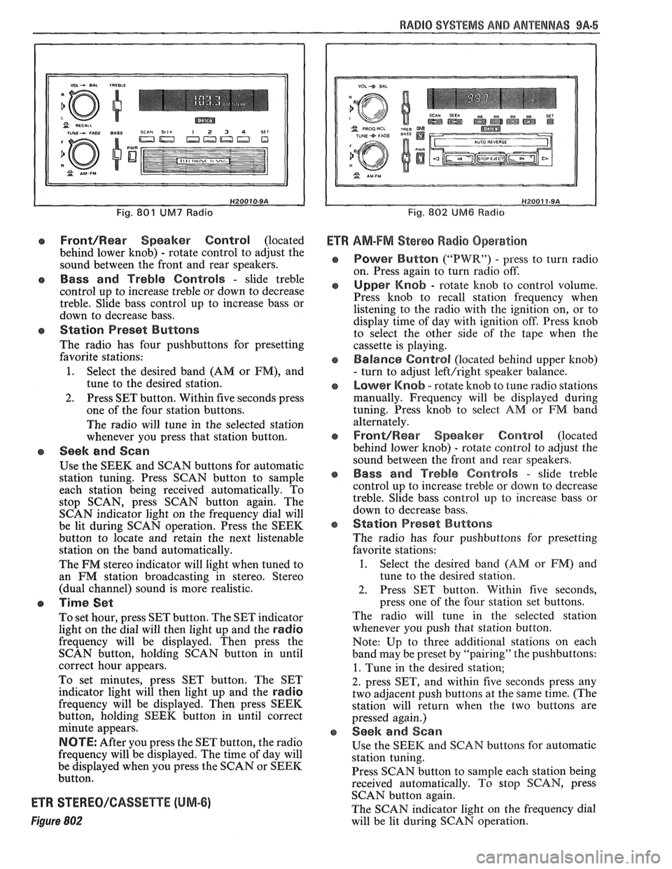
Fig. 801 UM7 Radio
Front/Rear Speaker Control (located
behind lower knob)
- rotate control to adjust the
sound between the front and rear speakers.
e Bass and Treble Controls - slide treble
control up to increase treble or down to decrease
treble. Slide bass control up to increase bass or
down to decrease bass.
e Station Preset Buttons
The radio has four pushbuttons for presetting
favorite stations:
1. Select the desired band (AM or FM), and
tune to the desired station.
2. Press SET button. Within five seconds press
one of the four station buttons.
The radio will tune in the selected station
whenever you press that station button.
e Seek and Scan
Use the SEEK and SCAN buttons for automatic
station tuning. Press SCAN button to sample
each station being received automatically. To
stop SCAN, press SCAN button again. The
SCAN indicator light on the frequency dial will
be lit during SCAN operation. Press the SEEK
button to locate and retain the next listenable
station on the band automatically.
The FM stereo indicator will light when tuned to
an FM station broadcasting in stereo. Stereo
(dual channel) sound is more realistic.
a Time Set
To set hour, press SET button. The SET indicator
light on the dial will then light up and the
radio
frequency will be displayed. Then press the
SCAN button, holding SCAN button in until
correct hour appears.
To set minutes, press SET button. The SET
indicator light will then light up and the
radio
frequency will be displayed. Then press SEEK
button, holding SEEK button in until correct
minute appears.
NOTE: After you press the SET button, the radio
frequency will be displayed. The time of day will
be displayed when you press the SCAN or SEEK
button.
ETR STEREO/GASSETTE (UM-6)
Figure 802
Fig. 802 UM6 Radio
Ef R AM-FM Stereo Radio Operation
Power Button ("PWR") - press to turn radio
on. Press again to turn radio off.
Upper Knob - rotate knob to control volume.
Press knob to recall station frequency when
listening to the radio with the ignition on, or to
display time of day with ignition off. Press knob
to select the other side of the tape when the
cassette is playing.
Balance Control (located behind upper knob)
- turn to adjust left/right speaker balance.
Lower Knob - rotate knob to tune radio stations
manually. Frequency will be displayed during
tuning. Press knob to select
AM or FM band
alternately.
Front/Rearr Speaker Control (located
behind lower knob)
- rotate control to adjust the
sound between the front and rear speakers.
Bass and Treble Controls - slide treble
control up to increase treble or down to decrease
treble. Slide bass control
up to increase bass or
down to decrease bass.
Station Preset Buttons
The radio has four pushbuttons for presetting
favorite stations:
1. Select the desired band (AM or FM) and
tune to the desired station.
2. Press SET button. Within five seconds,
press one of the four station set buttons.
The radio will tune in the selected station
whenever you push that station button.
Note: Up to three additional stations on each
band may be preset by "pairing" the pushbuttons:
1. Tune in the desired station;
2. press SET, and within five seconds press any
two adjacent push buttons at the same time. (The
station will return when the two buttons are
pressed again.)
Seek and Sean
Use the SEEK and SCAN buttons for automatic
station tuning.
Press SCAN button to
sample each station being
received automatically. To stop SCAN, press
SCAN button again.
The SCAN indicator light on the frequency dial
will be lit during SCAN operation.
Page 1656 of 1825
RADIO SVSEEMS AND ANTENNAS 9A-7
fully up. If this occurs, move it down until the
hiss disappears.
This radio has automatic Dynamic Noise
Reduction
(DNRB) to reduce high frequency
background hiss on AM, FM,
AM Stereo, FM
Stereo, and tape.
e Station Preset Buttons
The radio has four pushbuttons for presetting
favorite stations:
1. Select
the desired band (AM or
FM), and
tune to the desired station.
2. Press SET button. Within five secorads press
one of the four station buttons.
The radio will tune in the selected station
whenever you press that station button.
NOTE: Up to three additional stations on
each band may be preset by "pairing" the
pushbuttons:
1. Tune in the desired station;
2. press SET, and within five seconds press
any two
adjacant pushbuttons at the same
time. (The station will return when the two
buttons are pressed again.)
CB Seek and Scan
Use the SEEM and SCAN buttons for automatic
station tuning.
Press SCAN button to sample each station being
received automatically. To stop SCAN, press
SCAN button again.
The SCAN indicator light on the frequency dial
will be lit during SCAN operation.
Press the SEEK button to locate and retain the
next listenable station on the band automatically.
The
FM stereo indicator will light when tuned to
an
FM station broadcasting in stereo. Stereo
(dual channel) sound is more realistic.
o Time Set
To set hour, press SET button. The SET indicator
light on the dial will then light up. Then press
SCAN button, holding SCAN button in until
correct hour appears.
To set minutes, press SET button. The SET
indicator light will then light up. Then press
SEEK button, holding SEEK button in until
correct minute appears.
NOTE: After you press the SET button, the radio
frequency will be displayed. The time of day will
be displayed when you press the SCAN or SEEK
button.
e To Operate Tape Player:
Insert the cassette squarely through the door.
This automatically switches the unit from radio
to tape operation. If the sound is garbled (or there
is no sound), eject the tape and reinsert it
squarely.
To advance the tape, press the forward ("FWD")
button. To listen to the earlier portion of the tape,
press the reverse ("REV") button. To stop
forward or reverse movement, press the opposite
button lightly.
To listen to the next selection, slide the
"SEARCH" button to the right and press the forward
("FWD") button. The radio will seek the
next selection.
To listen to the previous selection again, slide the
"SEARCH" button to the right and press the
reverse ("REV") button. The radio will repeat
the previous selection.
The "ON" light, to the right of the search switch,
will be on while the search function is engaged.
When the left triangle indicator light is lit, the top
side of the tape is playing. When the right triangle
indicator light is lit, the bottom side of the tape
is playing.
To play the other side of the tape before the
present side has ended, press the upper left knob.
This will automatically play the opposite side of
the tape.
NOTE: When end-of-tape is reached in one
direction, the unit will automatically play the
other side of the tape. To remove the tape or listen
to the radio, push the EJECT button.
When the ignition is turned off, the tape is
automatically ejected.
The equalization setting which is desired will
vary according to the type of tape being used.
Chrome
(CrO,) and metal tapes usually have 70
usec equalization, while standard (iron) tapes
have
120 usec equalization. The tape bias is often
indicated on the cassette label or case.
Select the setting for proper tape equalization as
follows:
1. Select 70
usec (push button in).
2. Select 120 usec (button is out).
ADVANCED ETR TOUCH CONTROL
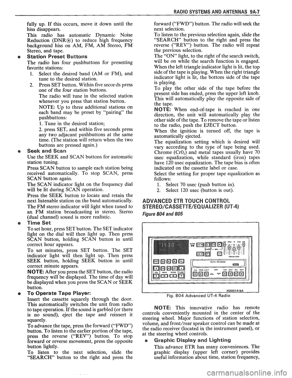
STEWEO/CASSETYE/EQUALIZER (hl"P-4)
Figure 804 and 806
NOTE: This innovative radio has remote
controls conveniently mounted in the center of the
steering wheel. Major functions of station selection,
volume, and
front/rear speaker control can be made at
the radio receiver (located in the instrument panel), or
at the steering wheel controls.
e Graphic Display and Lighting
This advance ETR has many conveniences. The
graphic display (upper left corner) provides
useful information about time, station frequency,
Page 1657 of 1825
9A-8 RADIO SYSTEMS AND ANTENNAS
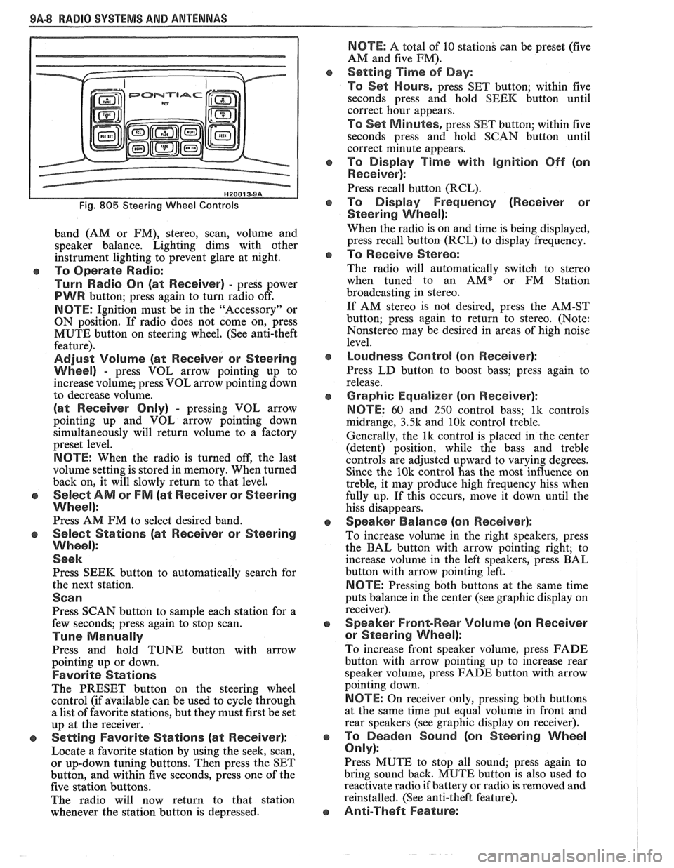
Fig. 805 Steering Wheel Controls
band (AM or FM), stereo, scan, volume and
speaker balance. Lighting dims with other
instrument lighting to prevent glare at night.
To Operate Radio:
Turn Radio On (at Receiver)
- press power
PWR button; press again to turn radio off.
NOTE: Ignition must be in the "Accessory" or
ON position. If radio does not come on, press
MUTE button on steering wheel. (See anti-theft
feature).
Adjust Volume (at Receiver or Steering
Wheel)
- press VOL arrow pointing up to
increase volume; press VOL arrow pointing down
to decrease volume.
(at Receiver Only) - pressing VOL arrow
pointing up and VOL arrow pointing down
simultaneously will return volume to a factory
preset level.
NOTE: When the radio is turned off, the last
volume setting is stored in memory. When turned
back on, it will slowly return to that level.
Select AM or FM (at Receiver or Steering
Wheel):
Press AM FM to select desired band.
Select Stations (at Receiver or Steering
Wheel):
Seek
Press SEEK button to automatically search for
the next station.
Scan
Press SCAN button to sample each station for a
few seconds; press again to stop scan.
Tune Manually
Press and hold TUNE button with arrow
pointing up or down.
Favorite Stations
The PRESET button on the steering wheel
control (if available can be used to cycle through
a list of favorite stations, but they must first be set
up at the receiver.
e Setting Favorite Stations (at Receiver):
Locate a favorite station by using the seek, scan,
or up-down tuning buttons. Then press the SET
button, and within five seconds, press one of the
five station buttons.
The radio will now return to that station
whenever the station button is depressed.
NBTE: A total of 10 stations can be preset (five
AM and five
PM).
Setting Time of Day:
To Set Hours,
press SET button; within five
seconds press and hold SEEK button until
correct hour appears.
TO Set M inlotes, press SET button; within five
seconds press and hold SCAN button until
correct minute appears.
To Display Time with ignition Off (on
Receiver):
Press recall button (RCL).
To Display Frequency (Receiver or
Steering
Wheel):
When the radio is on and time is being displayed,
press recall button (RCL) to display frequency.
To Receive Stereo:
The radio will automatically switch to stereo
when tuned to an
AMQr FM Station
broadcasting in stereo.
If AM stereo is not desired, press the AM-ST
button; press again to return to stereo. (Note:
Nonstereo may be desired in areas of high noise
level.
Loudness Control (on Receiver):
Press LD button to boost bass; press again to
release.
Graphic Equalizer (on Receiver):
NOTE:
60 and 250 control bass; lk controls
midrange,
3.5k and 10k control treble.
Generally, the
lk control is placed in the center
(detent) position, while the bass and treble
controls are adjusted upward to varying degrees.
Since the
10k control has the most influence on
treble, it may produce high frequency hiss when
fully up. If this occurs, move it down until the
hiss disappears.
Speaker Balance (on Receiver):
To increase volume in the right speakers, press
the BAL button with arrow pointing right; to
increase volume in the left speakers, press BAL
button with arrow pointing left.
NBTE: Pressing both buttons at the same time
puts balance in the center (see graphic display on
receiver).
Speaker Front-Wear Volume (on Receiver
or Steering Wheel):
To increase front speaker volume, press FADE
button with arrow pointing up to increase rear
speaker volume, press FADE button with arrow
pointing down.
NOTE: On receiver only, pressing both buttons
at the same time put equal volume in front and
rear speakers (see graphic display on receiver).
To Deaden Sound (on Steering Wheel
Only):
Press MUTE to stop all sound; press again to
bring sound back. MUTE button is also used to
reactivate radio if battery or radio is removed and
reinstalled. (See anti-theft feature).
Anti-Theft Feature:
Page 1674 of 1825
MISCELLANEOUS ACCESSORIES 96-4
SCELLANEOUS ACCESSOR
General Description ................................. 9G-1
Rally Gages .................................................. 9G- 1
Tachometer ................................................. 9G- 1
Trip Odometer
............................................. 9G- 1
Electric Rear Window Defogger ................. 9G-2
Power Remote Control Rearview
Mirror ........................................................ 9G-2
Diagnosis .................................................... 9G-2
Rally Gages ............................................... 9G-2
Tachometer .................................... .... .... 9G-2
Electric Rear Window Defogger ................. 9G-2
Power Remote Control Rearview
Mirror ........................................................ 96-2
Dash and Console Mounted
Accessory Switches
................................. 9G-4
General Description .................................. 9G-4
Electronic Glare Control Mirror ................. 9G-4
On-Car Service ............................................. 9G-4
Rally Gages, Tach ....................................... 96-4.
Rear Window Defogger ............................ 96-4.
Power Remote Control Mirror .................... 9G-4
GENERAL BESCRIP"T0N
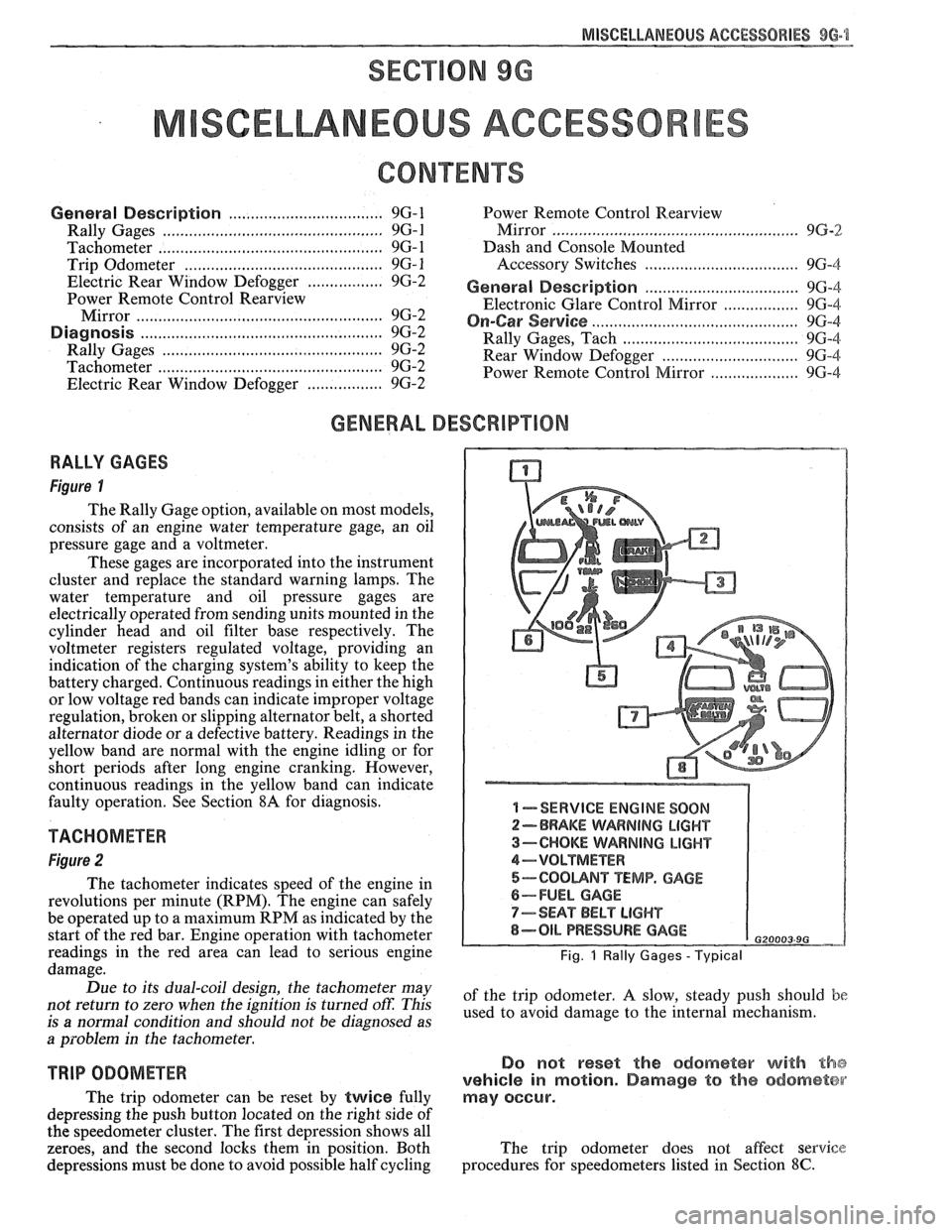
RALLY GAGES
Figure I
The Rally Gage option, available on most models,
consists of an engine water temperature gage, an oil
pressure gage and a voltmeter.
These gages are incorporated into the instrument
cluster and replace the standard warning lamps. The
water temperature and oil pressure gages are
electrically operated from sending units mounted in the
cylinder head and oil filter base respectively. The
voltmeter registers regulated voltage, providing an
indication of the charging system's ability to keep the
battery charged. Continuous readings in either the high
or low voltage red bands can indicate improper voltage
regulation, broken or slipping alternator belt,
a shorted
alternator diode
or a defective battery. Readings in the
yellow band are normal with the engine idling or for
short periods after long engine cranking. However,
continuous readings in the yellow band can indicate
faulty operation. See Section
8A for diagnosis.
TACHOMETER
Figure 2
The tachometer indicates speed of the engine in
revolutions per minute (RPM). The engine can safely
be operated up to a maximum RPM as indicated by the
start of the red bar. Engine operation with tachometer
readings in the red area can lead to serious engine
damage.
Due to its dual-coil design, the tachometer may
not return to zero when the ignition
is turned oft: This
is
a normal condition and should not be diagnosed as
a problem in the tachometer.
TRIP ODOMETER
The trip odometer can be reset by twice fully
depressing the push button located on the right side of
the speedometer cluster. The first depression shows all
zeroes, and the second locks them in position. Both
depressions must be done to avoid possible half cycling
I -SERVICE ENGINE SOON
2-BRAKE WARNING LIGHT
3-CHOKE WARNING LIGHT
4-VOLTMETER
5-COOUNT TEMP. GAGE
6-FUEL GAGE
7-SEAT BELT LIGHT
8-OIL PRESSURE GAGE G20003 9G
Fig. 1 Rally Gages - Typical
of the trip odometer. A slow, steady push should be
used to avoid damage to the internal mechanism.
Do not reset the odometer with the
vehicle in motion. Damage to the odometer
may occur.
The trip odometer does not affect service
procedures for speedometers listed in Section
8C.
Page 1677 of 1825
96.4 MISCELLANEOUS ACCESSORIES
DASH AND CONSOLE MOUNTED ACCESSORY
SWITCHES
Installation for various dash and console
mounted accessory switches is shown in Section
8C.
GENERAL DESCRIPIIOM
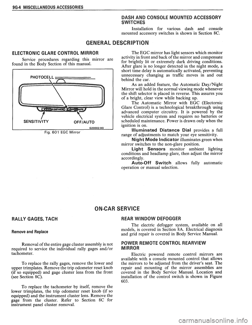
ELECTRONIC GLARE CONTROL MIRROR
Service procedures regarding this mirror are
found in the Body Section of this manual.
Fig. 601 EGC Mirror
The EGC mirror has light sensors which monitor
activity in front and back of the mirror and compensate
for brightly lit or extremely dark driving conditions.
After glare is no longer detected in the night mode, a
short time delay is automatically activated, preventing
unnecessary changing as traffic moves in and out
behind the car.
As an added feature, the Automatic
Day/Night
Mirror will hold in the normal viewing mode whenever
the shift selector is placed in reverse. This assures you
of a bright, clear view while backing up.
The Automatic Mirror with EGC (Electornic
Glare Control) is a technological breakthrough using
advanced computer circuitry. It is powered by the
vehicle electrical system and requires no batteries or
scheduled maintenance. Power is drawn only when the
ignition is on.
Illuminated Distance Dial provides a full
range of adjustments to match your eye sensitivity.
Night Mode Indicator illuminates green when
mirror switches to the non-glare position.
Light Sensors monitor ambient lighting
conditions and
headlamp glare, then adjust the mirror
accordingly.
Auto-Off Switch allows fully automatic
operation or manual selection.
ON-CAR SERVICE
RALLY GAGES, TACH REAR WINDOW DEFOGGER
Remove
and Replace
The electric defogger system, available on all
models, is covered in Section
8A. Electrical diagnosis
and grid repair is covered in Body Service Manual.
Removal of the entire gage cluster assembly is not
POWER RmOTE CONTROL REARVIEW
required to service the individual rally gages and/or MIRROR
tachometer.
Electric powered remote control mirrors are
available with a console mounted control that allows
To replace the rally gages, remove the lower and the
mirrors to be adjusted from the driver's seat. The
upper trimplates. Remove the trip odometer reset knob repair
and mounting of the mirror assemblies are
(if so equipped) and gage cluster lens from the front covered in
the Body Service Manual. Location and
(see Section
8C). installation of the control switch is shown in Figure
603.
To replace the tachometer by itself, remove the
lower trimplates, the trip odometer reset knob (if so
equipped) and the instrument cluster lens. Remove the
gage from the cluster. Refer to Section
8C for
hstrument panel cluster removal.
Page 1733 of 1825
5H-20 DOORS - F STYLE
Removal and Installation
1.
Raise door window. Remove door trim panel and
inner panel water deflector.
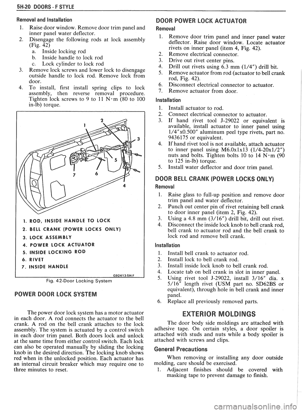
2. Disengage the following rods at lock assembly
(Fig. 42)
a. Inside locking rod
b. Inside handle to lock rod
c. Lock cylinder to lock rod
3. Remove lock screws and lower lock to disengage
outside handle to lock rod. Remove lock from
door.
4. To install, first install spring clips to lock
assembly, then reverse removal procedure.
Tighten lock screws to 9 to
11 Nem (80 to 100
in-lb) torque.
1. ROD, INSIDE HANDLE TO LOCK
2. BELL CRANK (POWER LOCKS ONLY)
3. LOCK ASSEMBLY
4. POWER LOCK ACTUATOR
4. INSIDE LOCKING ROD
6. RIVET
7. INSIDE HANDLE
G92413-5H-F
Fig. 42-Door Locking System
POWER DOOR LOCK SYSTEM
The power door lock system has a motor actuator
in each door.
A rod connects the actuator to the bell
crank. A rod on the bell crank attaches to the lock
assembly. The system is actuated by a control switch
in each door trim panel. Both doors lock and unlock
at the same time from either control switch. Each lock
can also be operated manually by sliding the locking
knob in the desired direction. The locking knob shows
red when in the unlocked position. Each actuator has
an internal circuit breaker which may require one to
three minutes to reset.
DOOR POWER LOCK ACTUATOR
Removal
Remove door trim panel and inner panel water
deflector. Raise door window. Locate actuator
rivets on inner panel (item
4, Fig. 42).
Remove electrical connector.
Drive out rivet center pins.
Drill out rivets using 6.3 mm
(1/4") drill bit.
Remove actuator from rod (actuator to bell crank
rod, Fig. 42).
Disconnect electrical connector to actuator.
Remove actuator from door.
Installation
1. Install actuator to rod.
2. Connect electrical connector to actuator.
3. If hand rivet tool J-29022 or equivalent is
available, install actuator to inner panel using
1/4"x0.500" aluminum peel type rivets, part no.
9436175 or equivalent.
4. If hand rivet tool is not available, attach actuator
to inner panel using
M6.0~1~13 (1/4-20x1/2")
nuts and bolts. Tighten bolts 10 to 14 N-m (90
to 125 in-lb) torque.
5. Install water deflector and door trim panel.
DOOR BELL CRANK (POWER LOCKS ONLY)
Removal
1.
Raise glass to full-up position and remove door
trim panel and water deflector.
2. Punch out center pin of rivet retaining bell crank
to door inner panel (item 2, Fig. 42).
3. Using a
4.8 mm (3/16") drill bit, drill out rivet.
4. Disconnect the inside
lock knob to bell crank rod,
bell crank to actuator rod and the bell crank to
lock rod and remove bell crank.
Installation
1.
Install bell crank to actuator rod.
2. Install lock to bell crank rod.
3. Install inside lock knob to bell crank rod.
4. Locate tab on bell crank in slot in inner panel.
5. Using rivet tool J-29022, install 3/16" dia. x
5/16" length rivet (USM part no.
SD62BS or
equivalent), through hole in bell crank and inner
panel.
6. Replace all previously removed parts.
EXTERIOR MOLDINGS
The door body side moldings are attached with
adhesive tape. On certain styles, a door spoiler is
attached with studs and nuts while a body spoiler is
attached with screws and clips.
General Precautions
When removing or installing any door outside
molding, care should be exercised.
1. Adjacent finishes should be covered with
masking tape to prevent damage to finish.