ignition coil PONTIAC FIERO 1988 Service Workshop Manual
[x] Cancel search | Manufacturer: PONTIAC, Model Year: 1988, Model line: FIERO, Model: PONTIAC FIERO 1988Pages: 1825, PDF Size: 99.44 MB
Page 1553 of 1825
RADIO I
(Continued from previous page) from back of Radio
If noise persists with replacement antenna, the
problem must be repaired at the source of noise
(generator, ignition system, accessory, etc.). See
Delco Manual for noise "Sniffing" procedures.
Ignition Noise
Trv the following. fixes in the piven order: 8. Install a braided ground strap on the hood. Replace
defective antenna with a good antenna.
If noise disappears repair or replace the defective
antenna. Check antenna ground, Coaxial Cable
Braid, and ground at connectors.
unplugged
- -
1. Check
for loose or defective spark plug wire.
2. Check for defective spark plug.
3. Move all wiring away from Ignition System
and spark plug wires. Antenna
noise
4. Reroute spark plug wires laying against
anything that could possibly transmit noise
to the Radio (car
g or sensor leads that
travel into the passenger compartment).
5. Inspect Ignition system for the following
and replace if necessary:
r Distributor cap carbon ball eroded away,
cracked or loose cap.
A rotor with burned black spot on wiper or
pits in wiper surface.
r A defective coil.
r An oily film on some of the lead terminals or
inside the cap.
Defective
WE1 module; can cause ignition
noise on
FM only.
6. Replace distributor cap and rotor.
9. Check Heater Core ground; clean or install a
braided ground strap if necessary.
10. Check air conditioner accumulator ground;
clean or install a braided ground strap if
necessarv.
TO STEERING
BRAIDED
GROUN GO LUMN
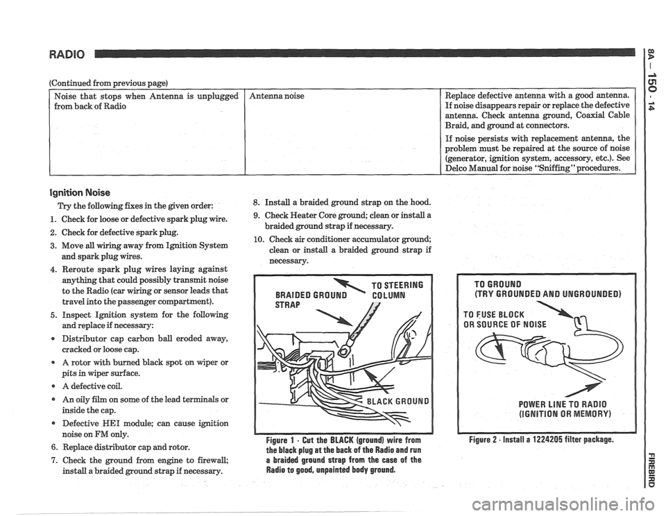
Figure 1 - Gut the BLACK (ground) wire from
the black plug
at the back of the Radio and run
7. Check the ground from engine to firewall, a braided ground strap from the ease of the
install a braided ground strap if necessary. Radio to good, unpainted body ground.
(TRY GROUNDED AND UNGROUNDED)
POWER LlNE TO RADIO
(IGNITION OR MEMORY)
Figure 2 - install a 1224205 filter package.
Page 1559 of 1825
POWER ANTENNA
(Continued from previous page) the relay contacts. The motor drives the
Antenna up. At the end of its travel, the Up
Switch opens and the motor stops.
A: ANTENNA DOES NOT OPERATE When the Radio or ignition is turned off,
(TABLE 2) the circuit through the Antenna Relay coil
opens. The contacts open to the position
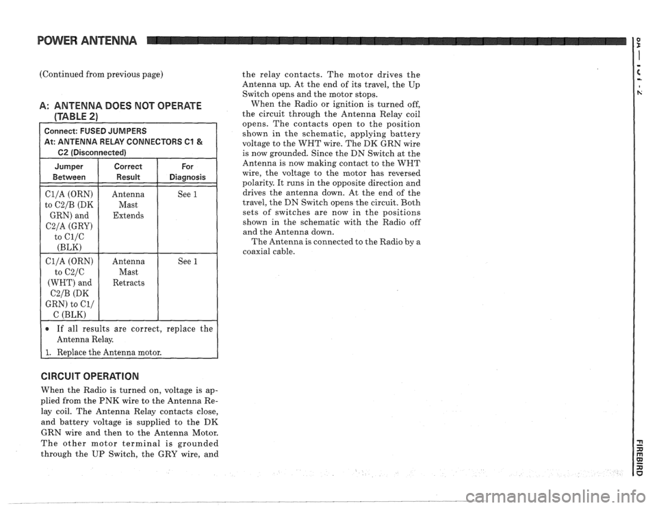
Connect: FUSED JUMPERS shown in the schematic, applying battery At: ANTENNA RELAY CONNECTORS C1 & voltage to the WHT wire. The DK GRN wire
1 62 (Disconnected) I
Cl/A (ORN)
to
C2/B (DK
GRN) and
C2/A (GRY)
to ci/c
(BLK)
Antenna
Mast
Extends See 1
If all results are correct,
replace the
Antenna Relay.
I 1. Redace the Antenna motor. is
now grounded.
Since the DN Switch at the
Antenna is now making contact to the WNT
wire, the voltage to the motor has reversed
polarity. It runs in the opposite direction and
drives the antenna down. At the end of the
travel, the DN Switch opens the circuit. Both
sets of switches are now in the positions
shown in the schematic with the Radio off
and the Antenna down.
The Antenna
is connected to the Radio by a
coaxial cable.
CIRCUIT OPERATION
When the Radio is turned on, voltage is ap-
plied from the PNK wire to the Antenna Re-
lay coil. The Antenna Relay contacts close,
and battery voltage is supplied to the
DK
GRN wire and then to the Antenna Motor.
The other motor terminal is grounded
through the UP Switch, the GRY wire, and
Page 1565 of 1825
COMPONENT LOCATION VIEWS I?
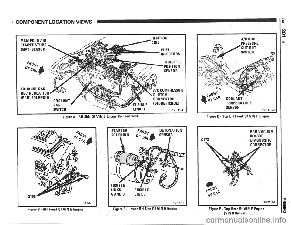
MANIFOLD AIR
TEMPERATURE
h
(MAT) SENSOR
EXHAUST GAS
RECIRCULATION
(EGR) SOLENOID
IGNITION
COIL
THROTTLE POSITION
-- -
SENSOR
FUEL
INJECTORS
SWITCH COMPRESSOR
TCN
CONNECTOR
FUSIBLE (DIODE INSIDE)
LINK ti 12Hll.l
Figure A - RN Side Of VIN E Engine Compartment
STARTER
FeOlyr DETONATION
SOLENOID SENSOR
a
Figure B - RH Front Of VlN E Engine Figure
C - Lower RH Side Of VIN E Engine Figure
D - Top LN Front
Of VIN E Engine
Figure E -Top Rear Of
VIN F Engine
(VIN 8 Similar)
Page 1665 of 1825
98-2 CRUISE CONTROL
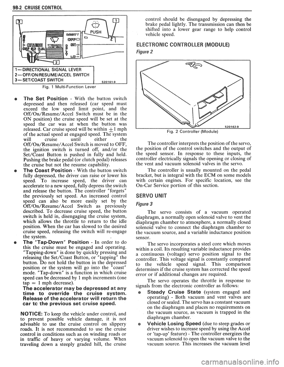
Fig. 1 Multi-Function Lever
e The Set Position - With the button switch
depressed and then released (car speed must
exceed the low speed limit point, and the
Off/On/Resume/Accel Switch must be in the
ON position) the cruise speed will be set at the
speed the car was at when the button was
released. Car cruise speed will be within
& 1 mph
of the actual speed at engaged speed. The system
will cruise until either the
Off/On/Resume/Accel Switch is moved to OFF,
the ignition switch is turned off, and/or the
Set/Coast Button is pushed in fully and held.
Pushing the brake pedal (or clutch pedal) releases
the cruise but not the resume capability.
The Coast Position - With the button switch
fully depressed, the driver can raise or lower his
speed. To increase speed, the driver can
accelerate to a new speed, fully depress the switch
and release the button. The controller "forgets"
the previously set speed. An increased control
speed can also be more easily set by the
Off/On/Resume/Accel Switch as previously
described. To decrease cruise speed, the button
switch is held in, disengaging the cruise system,
which allows the throttle to return to the idle
position. When the car has slowed to the aesired
cruise speed, releasing the switch will re-engage
the system.
e The "Tap-Down" Position - In order to do
this the cruise must be engaged and operating.
"Tapping-down" is done by quickly pressing and
releasing the
Set/Coast Button, or "tapping" the
button. Do not hold the button in the depressed
position or the system will go into the "coast"
mode. "Tap-down" is a function in which cruise
speed can be decreased by
1 mph increments (one
tap = 1 mph decrease).
The accelerator may be depressed at any
time
to override the cruise system.
Release of the accelerator will return the
car
te the previous set cruise speed.
NOTICE:
To keep the vehic:e under control, and
to prevent possible vehicle damage, it is not
advisable to use the cruise control on slippery
roads. It is not recommended to use the cruise
control in conditions such as on winding roads or
in traffic of heavy or varying volume. When
traveling down
a steeply graded hill, the cruise control
should be disengaged by depressing the
bralte pedal lightly. The transmission can then be
shifted into a lower gear range to help control
vehicle speed.
ELECTRONIC CONTROLLER (MODULE)
Figure 2
Fig. 2 Controller (Module)
The controller interprets the position of the servo,
the position of the control switches and the output of
the speed sensor. In response to these inputs, the
controller electrically signals the opening or closing of
the vent and vacuum solenoid valves in the servo.
The controller is usually mounted on the pedal
bracket, but is integral with the ECM on some models
with certain engines. For specific location, see the
On-Car Service portion of this section.
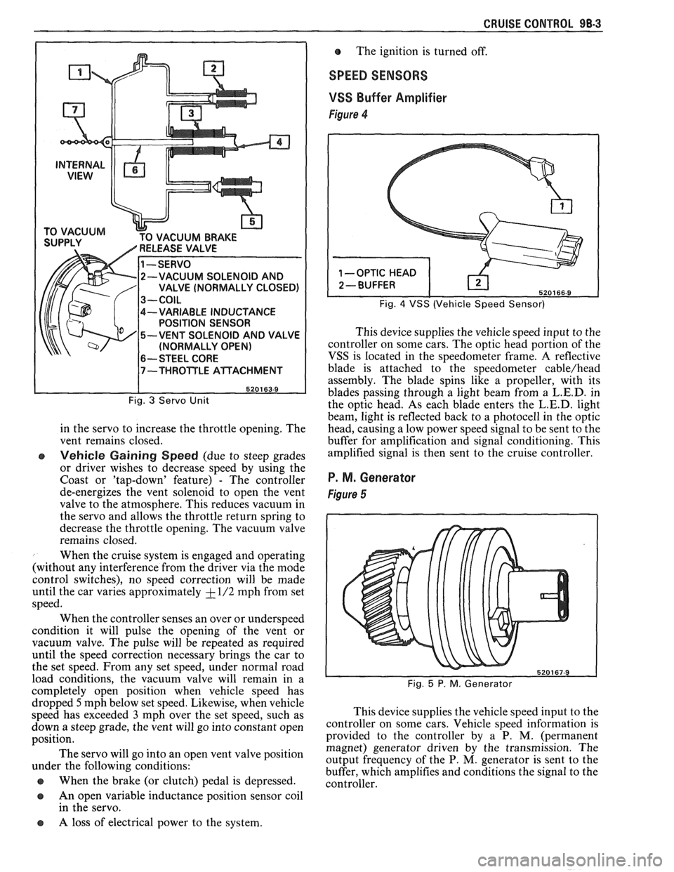
SERVO UNIT
Figure 3
The servo consists of a vacuum operated
diaphragm, a normally open solenoid valve to vent the
diaphragm chamber to atmosphere, a normally closed
solenoid valve to connect the diaphragm chamber to
the vacuum source, and a variable inductance position
sensor.
The servo incorporates a steel core which moves
within a coil. Its resulting variable inductance provides
a continuous (voltage) servo position signal to the
controller. This voltage signal is constantly compared
to the vehicle speed signal. This comparison
determines if the cruise system has corrected the speed
error or if additional changes are required.
The servo operates the throttle in response to
signals from the electronic controller as follows:
Steady Cruise State (system engaged and
operating)
- Both vacuum and vent valves are
closed or sealed. The servo has a constant vacuum
on the diaphragm and places no requirements on
the vacuum source, as vacuum is trapped in the
diaphragm chamber.
e Vehicle Losing Speed (due to steep grades or
driver wishes to increase speed by using the Accel
or 'tap-up' feature)
- The controller energizes the
vacuum solenoid to open the vacuum valve to the
vacuum source. This increases the vacuum level
Page 1666 of 1825
CRUISE CONTROL 98-3
CUUM BRAKE
-VARIABLE INDUCTANCE
POSITION SENSOR
-VENT SOLENOID AND VALVE
(NORMALLY OPEN)
6-- STEEL CORE
Fig. 3 Servo Unit
in the servo to increase the throttle opening. The
vent remains closed.
e Vehicle Gaining Speed (due to steep grades
or driver wishes to decrease speed by using the
Coast or 'tap-down' feature)
- The controller
de-energizes the vent solenoid to open the vent
valve to the atmosphere. This reduces vacuum in
the servo and allows the throttle return spring to
decrease the throttle opening. The vacuum valve
remains closed.
When the cruise system is engaged and operating
(without any interference from the driver via the mode
control switches), no speed correction will be made
until the car varies approximately
+ - 1/2 mph from set
speed.
When the controller senses an over or underspeed
condition it will pulse the opening of the vent or
vacuum valve. The pulse will be repeated as required
until the speed correction necessary brings the car to
the set speed. From any set speed, under normal road
load conditions, the vacuum valve will remain in a
completely open position when vehicle speed has The
ignition is turned off.
SPEED SENSORS
VSS
Buffer Amplifier
Figure 4
Fig. 4 VSS (Vehicle Speed Sensor)
This device supplies the vehicle speed input to the
controller on some cars. The optic head portion of the
VSS is located in the speedometer frame. A reflective
blade is attached to the speedometer
cable/head
assembly. The blade spins like a propeller, with its
blades passing through a light beam from a
L.E.D. in
the optic head. As each blade enters the
L.E.D. light
beam, light is reflected back to a photocell in the optic
head, causing a low power speed signal to be sent to the
buffer for amplification and signal conditioning. This
amplified signal is then sent to the cruise controller.
P. M. Generator
Figure 5
dropped 5mph below set speed. Likewise, when vehicle
speed has exceeded
3 mph over the set speed, such as This
device supplies the vehicle speed input to the
down a steep grade, the vent will go into ,-onstant open ~0ntI-011er on some cars. Vehicle speed information is
position. provided
to the controller by a P. M. (permanent
magnet) generator driven by the transmission. The
The servo go into an 'Pen vent position output frequency of the P. M, generator is sent to the under the following conditions:
buffer, which amplifies and conditions the signal to the
@ When the brake (or clutch) pedal is depressed. controller.
a An open variable inductance position sensor coil
in the servo.
a A loss of electrical power to the system.
Page 1674 of 1825
MISCELLANEOUS ACCESSORIES 96-4
SCELLANEOUS ACCESSOR
General Description ................................. 9G-1
Rally Gages .................................................. 9G- 1
Tachometer ................................................. 9G- 1
Trip Odometer
............................................. 9G- 1
Electric Rear Window Defogger ................. 9G-2
Power Remote Control Rearview
Mirror ........................................................ 9G-2
Diagnosis .................................................... 9G-2
Rally Gages ............................................... 9G-2
Tachometer .................................... .... .... 9G-2
Electric Rear Window Defogger ................. 9G-2
Power Remote Control Rearview
Mirror ........................................................ 96-2
Dash and Console Mounted
Accessory Switches
................................. 9G-4
General Description .................................. 9G-4
Electronic Glare Control Mirror ................. 9G-4
On-Car Service ............................................. 9G-4
Rally Gages, Tach ....................................... 96-4.
Rear Window Defogger ............................ 96-4.
Power Remote Control Mirror .................... 9G-4
GENERAL BESCRIP"T0N
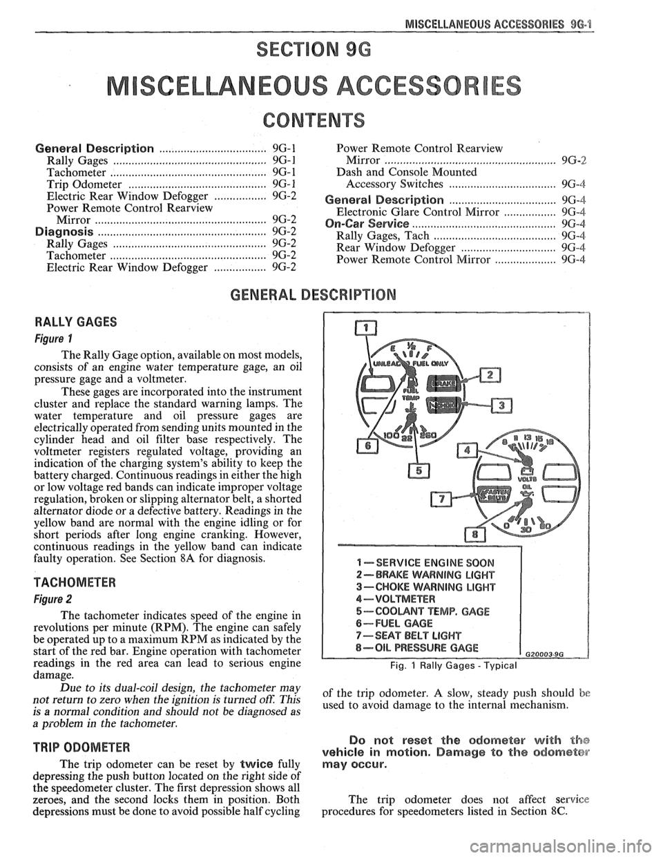
RALLY GAGES
Figure I
The Rally Gage option, available on most models,
consists of an engine water temperature gage, an oil
pressure gage and a voltmeter.
These gages are incorporated into the instrument
cluster and replace the standard warning lamps. The
water temperature and oil pressure gages are
electrically operated from sending units mounted in the
cylinder head and oil filter base respectively. The
voltmeter registers regulated voltage, providing an
indication of the charging system's ability to keep the
battery charged. Continuous readings in either the high
or low voltage red bands can indicate improper voltage
regulation, broken or slipping alternator belt,
a shorted
alternator diode
or a defective battery. Readings in the
yellow band are normal with the engine idling or for
short periods after long engine cranking. However,
continuous readings in the yellow band can indicate
faulty operation. See Section
8A for diagnosis.
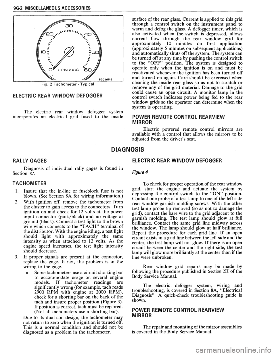
TACHOMETER
Figure 2
The tachometer indicates speed of the engine in
revolutions per minute (RPM). The engine can safely
be operated up to a maximum RPM as indicated by the
start of the red bar. Engine operation with tachometer
readings in the red area can lead to serious engine
damage.
Due to its dual-coil design, the tachometer may
not return to zero when the ignition
is turned oft: This
is
a normal condition and should not be diagnosed as
a problem in the tachometer.
TRIP ODOMETER
The trip odometer can be reset by twice fully
depressing the push button located on the right side of
the speedometer cluster. The first depression shows all
zeroes, and the second locks them in position. Both
depressions must be done to avoid possible half cycling
I -SERVICE ENGINE SOON
2-BRAKE WARNING LIGHT
3-CHOKE WARNING LIGHT
4-VOLTMETER
5-COOUNT TEMP. GAGE
6-FUEL GAGE
7-SEAT BELT LIGHT
8-OIL PRESSURE GAGE G20003 9G
Fig. 1 Rally Gages - Typical
of the trip odometer. A slow, steady push should be
used to avoid damage to the internal mechanism.
Do not reset the odometer with the
vehicle in motion. Damage to the odometer
may occur.
The trip odometer does not affect service
procedures for speedometers listed in Section
8C.
Page 1675 of 1825
9G-2 MISCELLANEOUS ACCESSORIES
Fig. 2 Tachometer - Typical
RPMX I00 €31-
ELECTRIC REAR WINDOW DEFOGGER
surface of the rear glass. Current is applied to this grid
through a control switch on the instrument panel to
warm and defog the glass. A defogger timer, which is
also activated when the switch is depressed, allows
current flow through the rear window grid
for
approximately 10 minutes on first application
(approximately
5 minutes on subsequent applications)
and automatically shuts off the system. The system can
be turned off at any time by pushing the control switch
to the "OFF" position. The system is designed to
operate only when the ignition is on and must be
reactivated whenever the ignition has been turned off
and turned on again. Care should be exercised when
cleaning the inside rear glass so as not to scratch or
remove any of the grid material. Damage to the grid
could cause an open circuit. A monitor lamp in-the
control switch indicates power being fed to the rear
window grids so the operator can determine when the
system is operating.
The electric rear window defogger system
incorporates an electrical grid fused to the inside
POWER REMOTE CONTROL REARVIEW
MIRROR
Electric powered remote control mirrors are
available with a control that allows the mirrors to be
adjusted from the driver's seat.
RALLY GAGES ELECTRIC REAR WINDOW DEFOGGER
Diagnosis of individual rally gages is found in
Section
8A Figure 4
TACHOMETER To check for moper o~eration of the rear window
1. Insure that the in-line or fuseblock fuse is not
blown. (See Section 8A for wiring information.)
2. With ignition off, remove the tachometer from
the cluster to gain access to the connectors. Turn
ignition on and check for
12 volts at the power
input connector
(pink/black) and no voltage at
ground (black). Connect a test light to the brown
wire which connects to the "TACH" terminal of
the distributor. With the engine idling, a test light
should light with approximately the same
intensity as when attached to
12 volts. As the
engine speed increases, the test light intensity
should decrease.
3. If proper signals are present at the connector,
replace the gage. If not, the problem is in the
wiring to the gage.
Some tachometers use a circuit shorting bar
to accommodate usage on several engine
models. If tachometer readings are
significantly wrong (for example, tach reads
2900 RPM with engine at 2000 RPM),
check for a shorting bar on the back of the
tach and insure proper position (Figure
3).
If position is correct, tach must be repaired.
(Not all tachometers use a shorting bar).
Due to its dual-coil design, the tachometer
may
- grid, start the engine a& actuate the system by
depressing the control switch to the
"ON" position.
Contact one probe of a test lamp to one of the left side
rear window garnish molding screws. With the other
test lamp probe tip removed (so as not to damage the
grid), contact the bare wire to the grid adjacent to the
garnish molding. The test lamp should glow at full
brilliance. Contact the same grid line midway across
the window. The lamp should glow at half brilliance.
Repeat the procedure for each grid line. If an open
circuit exists in a grid line between the left side and the
center, the test lamp will not glow. If there is an open
circuit between the center and the right side, the test
lamp will glow more brilliantly at the center than if the
line were unbroken.
Rear window grid repairs may be made by
following the procedure published in
Section 2H of the
Body Service Manual.
The electric defogger system, wiring and
troubleshooting, is covered in Section
8A, "Electrical
Diagnosis". A quick-check troubleshooting guide is
shown.
POWER REMOTE CONTROL REARVIEW
MIRROR
not return to zero when tvhe ignition is turned off'.
This is a normal condition and should not be The
repair and mounting of the mirror assemblies
diagnosed as a problem in the tachometer. is
covered in the Body Service Manual.