ignition coil PONTIAC FIERO 1988 Service Owner's Manual
[x] Cancel search | Manufacturer: PONTIAC, Model Year: 1988, Model line: FIERO, Model: PONTIAC FIERO 1988Pages: 1825, PDF Size: 99.44 MB
Page 711 of 1825
6E3-B-2 2.8L (VIN 5) DRIVEABILITY AND EMISSIONS
Problem may or may not turn "ON" the "Service Engine SoonJ' light, or store a code.
DO NOT use the trouble code charts in Section
"A" for intermittent problems. The fault must be
present to locate the problem. If a fault is
intermittent, use of trouble code charts may result
in replacement of good parts.
@ Most intermittent problems are caused by
faulty electrical connections or wiring. Perform
careful check as described at start of Section
"B". Check for:
@ Poor mating of the connector halves, or
terminals not fully seated in the connector
body (backed out).
@ Improperly formed or damaged terminals.
All connector terminals in problem circuit
should be carefully reformed to increase
contact tension.
@ Poor terminal to wire connection. This
requires removing the terminal from the
connector body to check. See "Introduction"
to Section
"6E".
@ If a visual check does not find the cause of the
problem, the car can be driven with a voltmeter
connected to a suspected circuit. A "Scan" tool
can also be used for monitoring input signals to
the ECM to help detect intermittent conditions.
An abnormal voltage, or "Scan" reading, when
the problem occurs, indicates the problem may
be in that circuit. If the wiring and connectors
check OK and a trouble code was stored for a
circuit having a sensor, except for Codes
43, 44,
and 45, substitute a known good sensor and
recheck. An
intermittent "Service Engine Soon" light
with no stored code may be caused by:
@ Ignition coil shorted to ground and arcing at
spark plug wires or plugs.
@ "Service Engine Soon" light wire to ECM
shorted to ground. (CKT 419).
@ Diagnostic "Test" terminal wire to ECM,
shorted to
ground.(CKT 451)
@ ECM power grounds. See ECM wiring
diagrams.
@ Loss of trouble code memory. To check,
disconnect TPS and idle engine until "Service
Engine Soon" light comes "ON". Code
22 should
be stored, and kept in memory when ignition is
turned "OFF". If not, the ECM is faulty.
@ Check for an electrical system interference
caused by a defective relay, ECM driven
solenoid, or switch. They can cause
a sharp
electrical surge. Normally, the problem will
occur when the faulty component is operated.
@ Check for improper installation of electrical
options, such as lights, 2-way radios, etc.
@ EST wires should be kept away from spark plug
wires, distributor wires, distributor housing,
coil, and generator. Wire from ECM to
distributor (CKT
453) should be a good
connection.
@ Check for open diode across A/C compressor
clutch, and for other open diodes (see wiring
diagrams).
HARD START
Definition: Engine cranks OK, but does not start for a long
time. Does eventually run, or may start hut immediately dies.
@ Perform careful check as described at start of -
Section "B".
@ Make sure driver is using correct starting
procedure.
@ CHECK:
- TPS for sticking or binding or a high TPS
voltage with the throttle closed (should read
less than
,700 volts).
- High resistance in coolant sensor circuit or
sensor itself. See Code 15 chart or with
a.
"Scan" tool compare coolant temperature with
ambient temperature on
a cold engine. 8
- Fuel pressure CHART A-7. Water contaminated
fuel.
EGR operation. Be sure valve seats properly and
is not staying open. See CHART C-7.
Both injector fuses (visually inspect).
Ignition system
- Check distributor for:
Proper output with ST-125.
Worn shaft.
Bare and shorted wires.
Pickup coil resistance and connections.
Loose ignition coil ground.
Moisture in distributor cap.
If problem exists in cold weather, check cold start
valve. See CHART A-9.
Page 712 of 1825
DRIVEABILITY AND EMISSIONS 2.8L (VIN S) 6E3-B-3
e A faulty in-tank fuel pump check valve will @ If engine starts but then immediately stalls,
allow the fuel in the lines to drain back to the open
distributor by-pass line. If engine then
tank after the engine is stopped. To check for starts
and runs OK, replace pickup coil.
this condition:
@ If engine starts and stalls, disconnect MAF
Perform Fuel System Diagnosis, CHART A-7. sensor. If engine then runs and sensor
@ Remove spark plugs. Check for wet plugs, connections are OK, replace the sensor.
cracks, wear, improper gap, burned
f lectrodes,
or heavy deposits. Repair or replace as
necessary.
HESITATION, SAG, STUMBLE
Definition: Momentary lack of response as the accelerator is pushed down. Can
occur at all car speeds.
Usually most severe when first trying to make the car move, as
from a stop sign. May cause the engine to stall if severe enough.
Perform careful visual check as described at
start of Section
"B".
a CHECK:
- Fuel pressure. See CHART A-7. Also check for
water contaminated fuel.
- Air leaks at air duct between MAF sensor and
throttle body.
- Spark plugs for being fouled or faulty wiring.
- PROM (2.8L) or MEM-CAL (5.OL & 5.7L)
number. Also check service bulletins for latest
MEM-CAL or PROM.
- TPS for binding or sticking. Voltage should
increase at a steady rate as throttle is moved
toward WOT.
- Ignition timing. See Emission Control
Information label.
- Generator output voltage. Repair if less than 9
or more than 16 volts.
- HE1 ground, CKT 453.
- Canister purge system for proper operation.
See CHART C-3.
- EGR - See CHART C-7.
@ Perform injector balance test CHART C-2A.
SURGES AND/OR CHUGGLE
Definition: Engine power variation under steady
throttle or cruise. Feels like the car speeds up and
slows down with no change in the accelerator pedal.
Be sure driver understands transmission
converter clutch and
A/C compressor operation
in Owner's Manual.
e Perform careful visual inspection as described
at start of Section
"B".
CHECK:
- TCC and 4th gear switch operation - See
CHART C-8A.
- Loose or leaking air duct between MAF sensor
and throttle body.
- Generator output voltage. Repair if less than 9
or more than 16 volts.
- EGR - There should be no EGR at idle. See
CHART C-7. Also check for plugged EGR
solenoid filter.
- Vacuum lines for kinks or leaks.
- Ignition timing. See Emission Control
Information label.
- In-line fuel filter. Replace ifdirty or plugged.
- Fuel pressure while condition exists. See
CHART A-7.
@ Inspect oxygen sensor for silicone contamination
from fuel, or use of improper RTV sealant. The
sensor may have a white, powdery coating and
result in a high but false signal voltage (rich
exhaust indication). The ECM will then reduce
the amount of fuel delivered to the engine,
causing a severe driveability problem.
@ Remove spark plugs. Check for cracks, wear,
improper gap, burned electrodes, or heavy
deposits. Also check condition of distributor cap,
rotor, and spark plug wires.
@ To help determine if the condition is caused by a
rich or lean system, the car should be driven at
the speed of the complaint. Monitoring block
learn at the complaint speed will help identify the
cause of the problem. If the system is runnig lean
(block learn greater than
138), refer to
"Diagnostic Aids" on
facing page of Code 44. If
the system is running rich (block learn less than
118), refer to "Diagnostic Aids" on facing page of
Code 45.
Page 714 of 1825
DWI\/EABILITV AND EMISSIONS 2.8L (VIN 5) 6E3-B-5
CU"T SUP, MISSES
Definition: Steady pulsation or jerking that follows engine
speed, usually more pronounced as engine load increases. The
exhaust has a steady spitting sound at idle or low speed.
@ Perform careful visual check as described at
start of Section
"B".
@ Check for missing cylinder by:
1. Disconnect IAC valve. Start engine.
Remove one spark plug wire at a time
using insulated pliers.
2. If there is an rpm drop on all cylinders
(equal to within
50 rpm), go to "ROUGH,
UNSTABLE, OR INCORRECT IDLE,
STALLING" symptom. Reconnect IAC
valve.
3. If
there is no rprn drop on one or more
cylinders, or excessive variation in drop,
check for spark on the suspected
cylinder(s) with J 26792 (ST-125) Spark
Gap Tool or equivalent.
If no spark, see
Section
"6D" for intermittent operation or
miss. If there is spark, remove spark
plug(s) in these cylinders and check for:
- Cracks
- Wear
- Improper gap
- Burned electrodes
- Iieavy deposits
@ Perform compression check on questionable
cylinder(s) found above. If compression is low,
repair as necessary. See Section
"6".
@ Disconnect all injector harness connectors.
Connect
5-34730-2 injector test light or
equivalent 6 volt test light between the
harness terms, of each injector connector and
note light while cranking. If test light fails to blink
at any connector, it is a faulty injector drive
circuit harness, connector, or terminal.
@ Perform the injector balance test. See CHART C-
2A.
s CHECK:
- Spark plug wires by connecting ohmmeter to
ends of each wire in question. If meter reads over
30,000 ohms, replace wire(s1.
- Fuel System - Plugged fuel filter, water, low
pressure. See
CHART A-7.
- Valve timing.
- Secondary voltage using a shop ocilliscope or a
spark tester 5-26792 (ST-125) or equivalent.
@ Visually inspect distributor cap and rotor for
moisture, dust, cracks, burns, etc. Spray cap and
plug wires with, fine water mist to check for
shorts.
@ A miss condition can be caused by EM1
(Electromagnetic Interference) on the reference
circuit.
EM1 can usually be detected by
monitoring engine rpm with a "Scan" tool. A
sudden increase in rpm with little change in
actual engine rpm change, indicates
EM1 is
present. If the problem exists, check routing of secondary
wires, check all distributor ground circuits.
@ Remove rocker covers. Check for bent pushrods,
worn rocker arms, broken valve springs, worn
camshaft lobes. Repair as necessary. See Section
"6A".
BACKFIRE
Definition: Fuel ignites in intake manifold, or
in exhaust system, making a loud popping noise.
CHECK:
- Loose wiring connector or air duct at MAF
sensor.
- Compression - Look for sticking or leaking
valves.
- EGR operation for being open all the time. See
CHART C-7.
- EGR gasket for faulty or loose fit .
- Valve timing.
- Output voltage of ignition coil using a shop
ocilliscope or spark tester 5-26792 (ST-125) or
equivalent.
- Spark plugs for crossfire also inspect (distributor
cap, spark plug wires, and proper routing of plug
wires).
- Ignition system for intermittent condition. (See
Section
"6D").
- Engine timing - see Emission Control
Information label.
- Perform fuel system diagnosis check, CIIART A-
7A.
- Perform injector balance test, CHART C-2A.
- Deceleration valve (2.8L ~nanualltrans) - See
Section
"C6".
- A.I.R. system check valves - See Section "C-6".
Page 723 of 1825
6E3-Cl-4 2.8L (VIN S) DRIVEABILITY AND EMISSIONS
BarWNeutral Switch (Auto Only)
The ParWNeutral (PIN) switch indicates to the
ECM when the transmission is in Park or Neutral.
This information is used for the TCC and the IAC
valve operation.
Important
Vehicle should not be driven with ParWNeutral
switch disconnected as idle quality will be affected
and a possible false Code
24 (VSS).
See Section "$A" for more information on the PIN
switch, which is part of the neutrallstart and backup
light switch assembly.
NC '"n" Signal
This signal tells the ECM that the A/C selector
Switch is turned on, and that the pressure cycling
switch is closed. The ECM uses this to adjust the idle
Speed when the air conditioning is working.
If this signal is not available to the ECM, idle may
be rough, especially when the
A/C compressor cycles.
The voltage at ECM terminal "B8" should equal
battery voltage when
AIC is requested and the
pressure cycling switch is closed.
The signal at
B8 will cause the ECM to turn on the
A/C clutch by energizing the A/C relay.
Distributor Reference Signal
The distributor sends a signal to the ECM to tell it
both engine RPM and crankshaft position. See EST
System for further information.
To read the codes, use a "Scan" tool or ground the
diagnostic terminal with the engine not running and
the ignition on. The "Service Engine Soon" light will
flash Code 12 three times and
then flash each code
stored in memory three times. All codes stored in
memory would have been read when Code 12 was
flashed again. No new codes can be stored when in the
Diagnostics Mode (diagnostics lead grounded).
This
eliminates confusion while the system is being worked
on. To clear the codes from memory:
@ Ignition off
@ Remove fuse located in a weather proof holder
located near the battery for 30 seconds.
Since the ECM can have
a failure which may
effect only one circuit, following the Diagnostic
Procedures in this section will determine which circuit
has a problem and where it is. If
a diagnostic chart indicates that the ECM
connections or ECM is the cause of
a problem and the
ECM is replaced, but does not correct the problem, one
of the following may be the reason:
€9
connections. - The diagnostic chart will say "ECM
connections or ECM. The terminals may have to be
removed from the connector in order to check them
properly.
@ The ECM or PROM is not correct for the
application.
- The incorrect components may cause a
malfunction and may or may not set a code.
@ The problem is intermittent. - This means that
the problem is not present at the time the system is
being checked. In this case, refer to the "Symptoms"
portion of the manual and make a careful physical
inspection of all portions of the system involved.
@ Shorted solenoid, relay coil, or harness. -
Solenoids and relays are turned "ON" and "OFF" by
the
ECM,using internal electronic switches called
"Drivers". Each driver is part of
a group of four called
"Quad-drivers". Failure of one driver can damage any
other driver in the set.
Solelloid and relay coil
resistance must measure more than 20 ohms. Less
resistance will cause early failure of the ECM
"driver". A shorted solenoid, relay coil, or harness,
with a GMP4 computer, will not damage the ECM, but
will cause the component to be inoperative.
Before replacing an ECM, be sure to check the coil
resistance of all solenoids and relays controlled by the
ECM. See ECM wiring diagram for the
solenoid(s)
and relay(s) and the coil terminal identification.
534636 or BT 8405 testers or equivalent provide
a fast, accurate means of checking for a shorted coil or
a short to battery voltage.
@ The PROM may be faulty. - Although these
rarely fail, it operates as part of the ECM. Therefore,
it could be the cause of the problem. Substitute a
known good PROM.
@ The replacement ECM may be faulty. - After the
ECM is replaced, the system should be rechecked for
proper operation. If the diagnostic chart again
indicates the ECM is the problem, substitute
a known
good ECM. Although this is a rare condition, it could
happen.
ECM
A faulty ECM will be determined in the diagnostic
charts or
by a Code 55.
PROM
A faulty PROM may result in a Code 51.
Page 755 of 1825
6E3-C2-20 2.8L (VIN S) DRIVEABILITY AND EMISSIONS
AIR THROTTLE FLOW BODY
LD START VALVE
8-5 BLUNVHT
BLUIBLK
GRMNVHT
. GRNIBLK
ECM
.
IAC COIL
"A" HI
IAC COIL "A" LO
IAC COIL "B" HI
C3 IAC COIL "B" LO
7-1 6-87
55 1800-6E
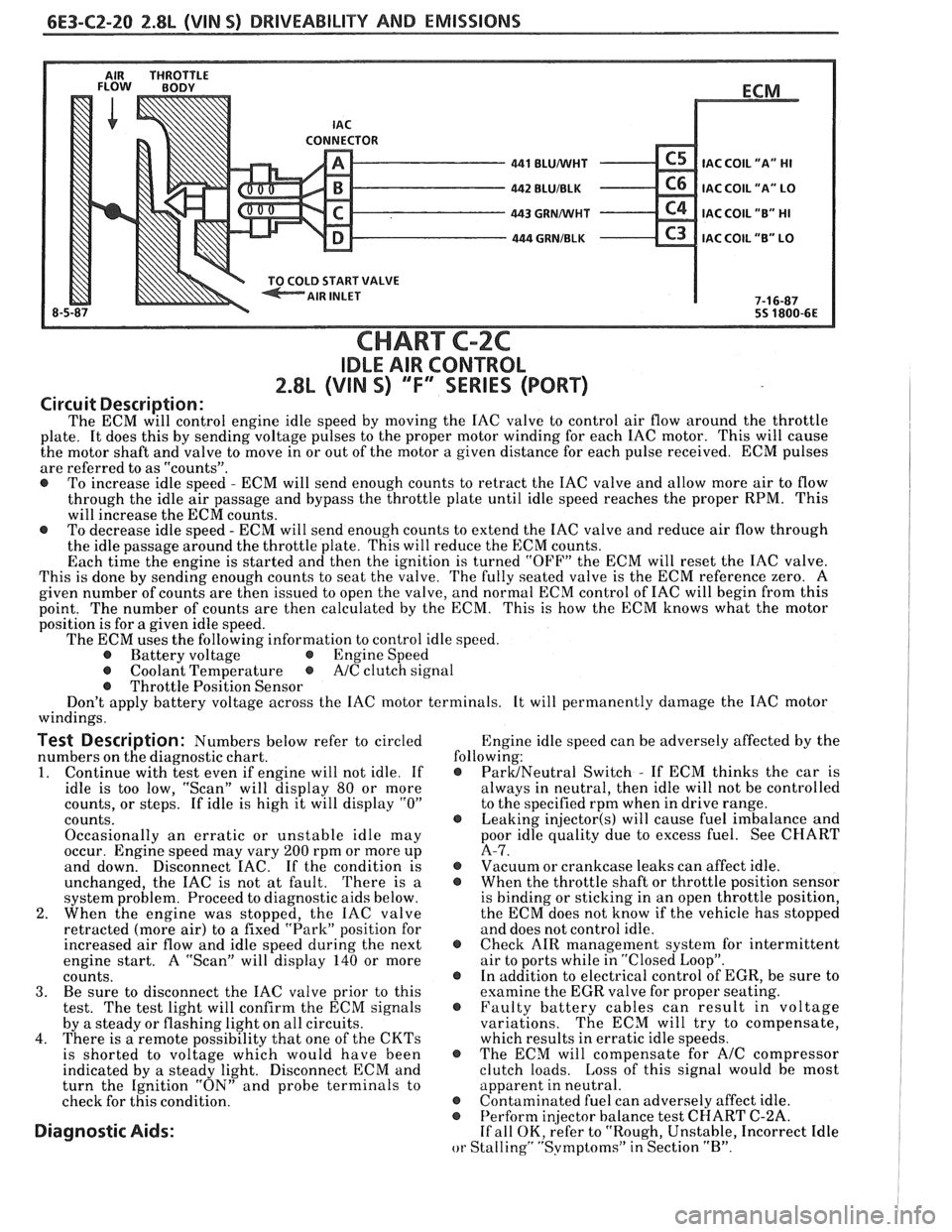
CHART C-2C
IDLE AIR CONTROL
2.8L (VIN S) ""F-SERIES (PORT)
Circuit Description:
The ECM will control engine idle speed by moving the IAC valve to control air flow around the throttle
plate. It does this by sending voltage pulses to the proper motor winding for each IAC motor. This will cause
the motor shaft and valve to move in or out of the motor a given distance for each pulse received. ECM pulses
are referred to as "counts".
@ To increase idle speed - ECM will send enough counts to retract the IAC valve and allow more air to flow
through the idle air passage and bypass the throttle plate until idle speed reaches the proper RPM. This
will increase the ECM counts.
@ To decrease idle speed - ECM will send enough counts to extend the IAC valve and reduce air flow through
the idle passage around the throttle plate. This will reduce the ECM counts.
Each time the engine is started and then the ignition is turned "OFF" the ECM will reset the IAC valve.
This is done by sending enough counts to seat the valve. The fully seated valve is the ECM reference zero. A
given number of counts are then issued to open the valve, and normal ECM control of IAC will begin from this
point. The
number of counts are then calculated by the ECM. This is how the ECM knows what the motor
position is for
a given idle speed.
The ECM uses the following information to control idle speed.
@ Battery voltage @ Engine Speed
@ Coolant Temperature @ A/C clutch signal
@ Throttle Position Sensor
Don't apply battery voltage across the IAC motor terminals. It will permanently damage the IAC motor
windings.
Test Description: Numbers below refer to circled Engine
idle speed can be adversely affected by the
numbers on the diagnostic chart. following:
1. Continue
with test even if engine will not idle. If @ ParUNeutral Switch - If ECM thinks the car is
idle is too low, "Scan" will display
80 or more always
in neutral, then idle will not be controlled
counts, or steps. If idle is high it will display
"0" to the specified rpm when in drive range.
counts.
@ Leaking injector(s) will cause fuel imbalance and
Occasionally an erratic or unstable idle may poor
idle quality due to excess fuel. See CHART
occur. Engine speed may vary
200 rpm or more up A-7.
and down. Disconnect
EAC. If the condition is @ Vacuum or crankcase leaks can affect idle.
unchanged, the IAC is not at fault. There is
a @ When the throttle shaft or throttle position sensor
system problem. Proceed to diagnostic aids below. is
binding or sticking in an open throttle position,
2. When the engine was stopped, the IAC valve the
ECM does not know if the vehicle has stopped
retracted (more air) to a fixed "Park" position for and does not control idle.
increased air flow and idle speed during the next
@ Check AIR management system for intermittent
engine start. A "Scan" will display
140 or more air
to ports while in "Closed Loop".
counts. @ In addition to electrical control of EGR, be sure to
3. Be sure to disconnect the IAC valve prior to this examine the
EGR valve for proper seating.
test. The test light will confirm the ECM signals @ Faulty battery cables can result in voltage
by a steady or flashing light on all circuits. variations. The
ECM will try to compensate,
4. There is a remote possibility that one of the CKTs which results in erratic idle speeds.
is shorted to voltage which would have been @ The ECM will compensate for A/C compressor
indicated by a steady light. Disconnect ECM and clutch
loads. Loss of this signal would be most
turn the Ignition "ON" and probe terminals to apparent
in neutral.
check for this condition.
@ Contaminated fuel can adversely affect idle. @ Perform in
or Stalling" "Svmptoms" in Section "B".
Page 765 of 1825
6E3-C4-2 2.8L (WIN S) DRIVEABILITY AND EMISSIONS
RESULTS OF INCORRECT OPERATION
An open or ground in the EST circuit will set a
Code 42 and cause the engine to run on the HE1
module timing. This will cause reduced performance
and poor fuel economy.
The ECM uses information from the
MAF and
coolant sensors in addition to rpm to calculate spark
~tdvance as follows:
@ Cold engine = more spark advance.
@ Engine under minimum load based on rpm
and low amount of air flow- more spark
advance. Hot engine
= less spark advance.
@ Engine under heavy load based on rprn and
high amount of air flow- less spark advance.
The description, operation, and diagnosis of the
HE1 system are found in Section "GD" of this manual.
CODE 12
Code 12 is used during the Diagnostic Circuit
Check procedure to test the code display ability of the
ECM. This code indicates that the ECM is not
receiving the engine
rpnl (REFERENCE) signal. This
occurs with the ignition key "ON" and the engine not
running.
The "Reference" signal also triggers the fuel
injection system. Without the "Reference" signal the
engine cannot run.
OM-CAR SERVICE
SETTING TIMING
The initial base timing is set by disconnecting the
timing connector, located near the blower motor.
Refer to Emission Control Information Label for
procedure.
This will cause Code 42 to store in the code
memory of the ECM.
The memory must be cleared
after setting timing.
How Code 42 Is Determined
When the system is running on the HE1 module,
that is no voltage on the bypass line, the
HE1 module
grounds the EST signal.
The ECk1 expects to see no
voltage
on the EST line during this condition. If it sees
a voltage, it sets code 42 and will not go into the EST
mode.
When the rpm for EST
is reachecl bout 300 rprn)
the ECM applies 5 volts to the bypass line and the E:SrI'
should no longer be grounded in the tIEI nodule so
the EST voltage should be varying.
If the bypass line is open or grounclecl, the IIEI
tnod~lle will not switch to EST mode so the EST
voltage will be low
and Code 42 will be set. Refer to
Section
"611" for on vehicle service.
PARTS INFORMATION
PART NAME GROUP
Controller, ECM
(Remanufi~ctured) ................ 3.670
.......................... Distributor 2.36 1
Module, Distr ........................ 3.380
........................... Coil, Distr 2.170
Page 767 of 1825
6E3-C4-4 2.8L (VIN S) DRIVEABILITY AND EMISSIONS
430 PPLMlHT - 85 - REFERENCE
424
TANIBLK
453 BLWRED
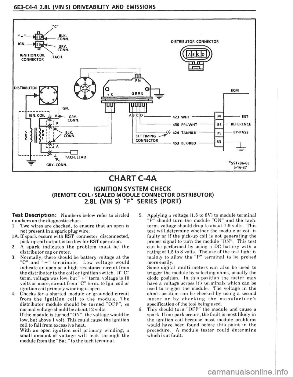
CHART C-4A
IGNITION SYSTEM CHECK
(REMOTE COIL / SEALED MODULE CONNECTOR DISTRIBUTOR)
2.8L (VIN 5) "F" SERIES (PORT)
Test Description: Numbers below refer to circled
numbers on the diagnostic chart.
1. Two wires are checked, to ensure that an open is
not present in
a spark plug wire.
1A. If spark occurs with EST connector disconnected,
pick-up coil output is too low for
EST operation.
2. A spark indicates the problem must be the
distributor cap or rotor.
3. Normally, there should he battery voltage at the
"C" and "+" terminals. Low voltage would
indicktte an open or a high resistance circuit from
the distributor to the coil or ignition switch. If
"C"
term. voltage was low, but " +" term. voltage is 10
volts or more, circuit from "C" term. to Ign. coil or
ignition coil primary winding is open.
4. Checks for a shorted module or grounded circuit
from the ignition coil to the module. The
distributor
nodule should be turned "OFF", so
normal voltage should be about
1% volts.
If the module is turned "ON", the voltage would be
low, but above
1 volt. 'I'his could cause the ig~lition
coil to fail from excessive heat.
With an open ignition coil primary
winding, i~
small amount of voltage will leak through the
module from the "Rat." to the tach terminal.
5. Applying a voltage (1.5 to 8V) to module terminal
"P" should turn the nlodule "ON" and the tach.
term. voltage should drop to about
7-9 volts. This
test will determine whether the module or coil is
faulty or if the pick-up coil is not generating the
proper signal to turn the
rnodule "ON". 'Phis test
can be performed by using a I)C battery with a
rating of
1.5 to 8 volts. The i~sc of the test light is
mainly to allow the
"P" terminal to be probed
more easily.
Some digital multi-meters can also be used t,o
trigger the module by selecting ohms, i~sually the
diode position. In this position the meter
may
have a voltage across it's terminals which can be
used to trigger the module.
'I'he voltage in the
ohm's position can be checked by
using a second
meter or by checking the manufacture's
specification of the tool being used.
6. This should turn "OFF" the nlodule and cause a
spark. If no
spark occurs, the fault is most likely in
the ignition coil because most module problems
would have been found before this point in the
procedure.
A moclule tester could determine
which is at fault.
Page 819 of 1825
6E3-A-16 S.OL (VIN F) & 5.7L(VIN 8) DRIVEABILITY AND EMISSIONS
430 PPWHT
PRIMARY COIL
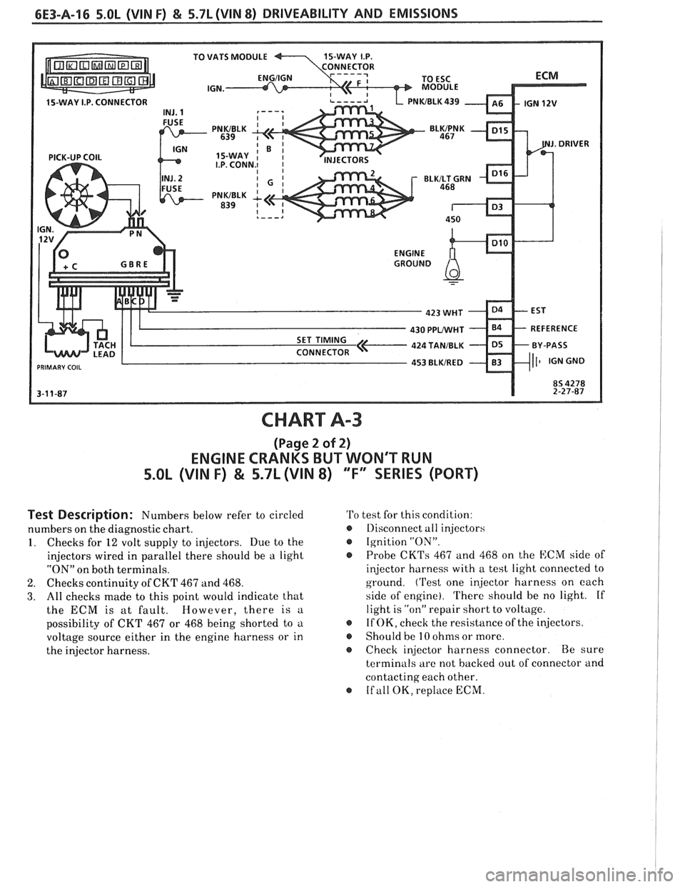
CHART A-3
(Page 2 of 2)
ENGINE CRANKS BUT WONT RUN
5.OL (VIN F) & 5.71 (VIN 8) "F" SERIES (PORT)
Test Description: Numbers below refer to circled
numbers on the diagnostic chart.
1. Checks for 12 volt supply to injectors. Due to the
injectors wired in parallel there should be a light
"ON" on both terminals.
2. Checks continuity of CKT 467 and 468.
3. All checks made to this point would indicate that
the ECM is at fault. However, there is a
possibility of CKT 467 or 468 being shorted to a
voltage source either in the engine harness or in
the injector harness.
'Po test for this condition:
@ Llisconnect all injectors
Ignition
"ON".
@ Probe CKTs 467 and 468 on the ECM side of
injector harness with a test light connected to
ground.
('rest one injector harness on each
side of engine). There should be no light. If
light is
"on" repair short to voltage.
If OK, check the resistance of the injectors.
o Should be 10 ohms or more.
s Check injector harness connector. Be sure
terminals are not backed out of connector and
contacting each other.
o If all OK, replace ECM.
Page 867 of 1825
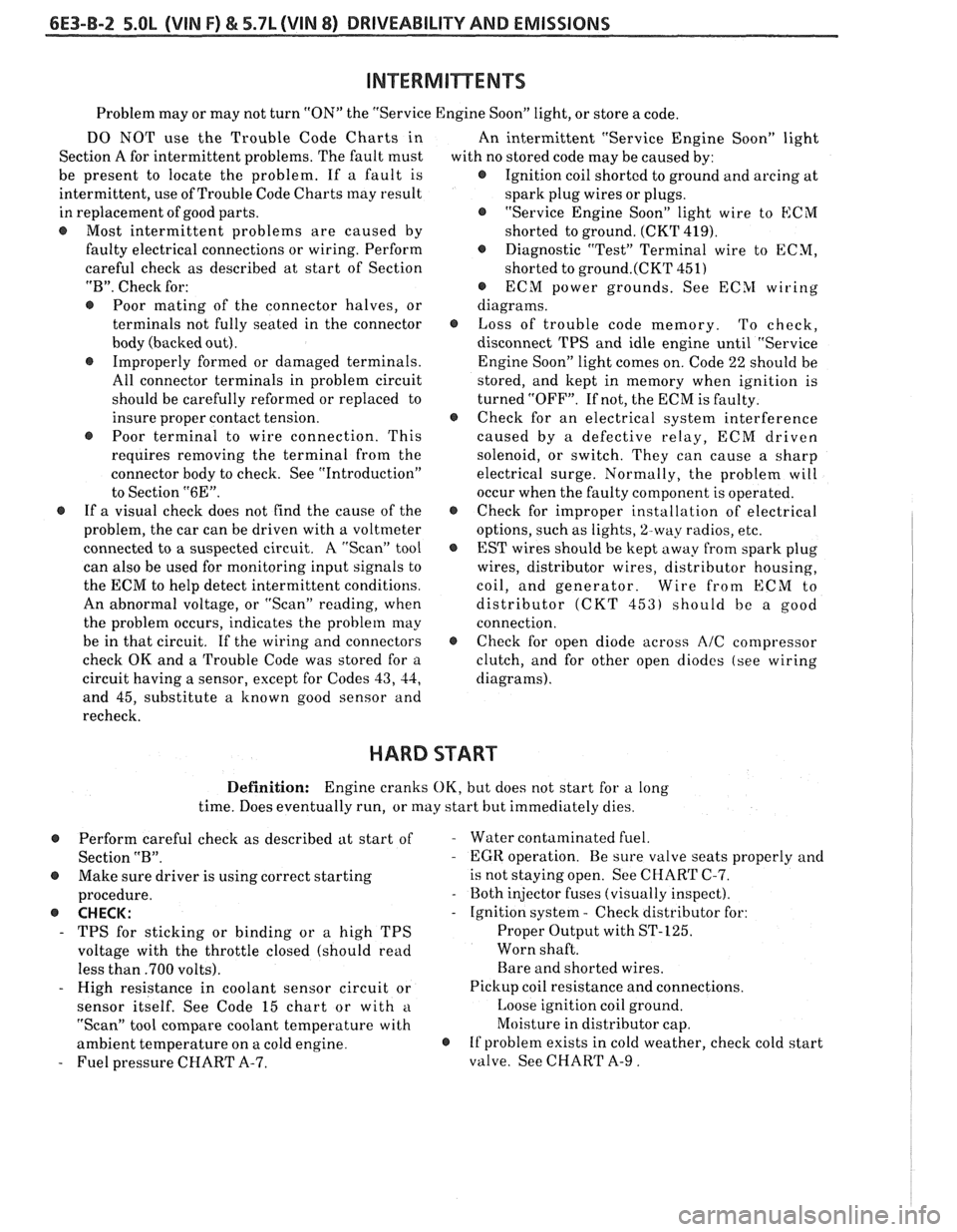
6E3-B-2 5.OL (VIN F) & 5.7L (VIN 8) DRIVEABILITY AND EMISSIONS
Problem may or may not turn "ON" the "Service Engine Soon" light, or store a code.
DO NOT use the Trouble Code Charts in
An intermittent "Service Engine Soon" light
Section A for intermittent problems. The fault must
with no stored code may be caused by:
be present to locate the problem. If a fault is
@ Ignition coil shorted to ground and arcing at
intermittent, use of Trouble Code Charts
may result
spark plug wires or plugs.
in replacement of good parts.
"Service Engine Soon" light wire to
ECM
@ Most intermittent problems are caused by
shorted to ground. (CKT 419).
faulty electrical connections or wiring. Perform
Diagnostic "Test" Terminal wire to ECM,
careful check as described at start of Section
shorted to
ground.(CKT 451)
"B". Check for:
@ ECM power grounds. See ECSI wiring
@ Poor mating of the connector halves, or diagrams.
terminals not fully seated in the connector
@ Loss of trouble code memory. To check,
body (backed out). disconnect TPS and idle engine until "Service
@ Improperly formed or damaged terminals.
Engine Soon" light comes on. Code 22 should be
All connector terminals in problem circuit
stored, and kept in memory when ignition is
should be carefully reformed or replaced to turned "OFF". If not, the ECM is faulty.
insure proper contact tension.
@ Check for an electrical system interference
@ Poor terminal to wire connection. This caused by a defective relay, ECM driven
requires removing the terminal from the
solenoid, or switch. They can cause a sharp
connector body to check. See "Introduction"
electrical surge. Normally, the problem will
to Section
"6E". occur when the faulty component is operated.
@ If a visual check does not find the cause of the @ Check for improper installation of electrical
problem, the car can be driven with a voltmeter
options, such as lights,
%way radios, etc.
connected to
a suspected circuit. A "Scan" tool
EST wires should be kept away from spark plug
can also be used for monitoring input signals to wires, distributor wires, distributor housing,
the ECM to help detect intermittent conditions. coil, and generator. Wire from
ECM to
An abnormal voltage, or "Scan" reading, when distributor
(CKT 453) should be a good
the problem occurs, indicates the problem
may connection.
be in that circuit. If the wiring and connectors
@ Check for open diode across AIC compressor
check OK and a Trouble Code was stored for a
clutch, and for other open diodes (see wiring
circuit having a sensor, except for Codes
43, 44, diagrams).
and 45, substitute a known good sensor and
recheck.
HARD START
Definition: Engine cranks OK, but does not start for a long
time. Does eventually run, or may start but immediately dies.
Perform careful check as described at start of
Section
"B".
@ Make sure driver is using correct starting
procedure.
@ CHECK:
- TPS for sticking or binding or a high TPS
voltage with the throttle closed (should read
less than
.700 volts).
- High resistance in coolant sensor circuit or
sensor itself. See Code 15 chart or with
a
"Scan" tool compare coolant temperature with
ambient temperature on a cold engine.
- Fuel pressure CHART A-7.
- Water contaminated fuel.
- EGR operation. Be sure valve seats properly and
is not staying open. See CHART C-7.
- Both injector fuses (visually inspect).
- Ignition system - Check distributor for:
Proper Output with ST-125.
Worn shaft.
Bare and shorted wires.
Pickup coil resistance and connections.
Loose ignition coil ground.
Moisture in distributor cap.
@ If problem exists in cold weather, check cold start
valve. See CHART A-9.
Page 868 of 1825
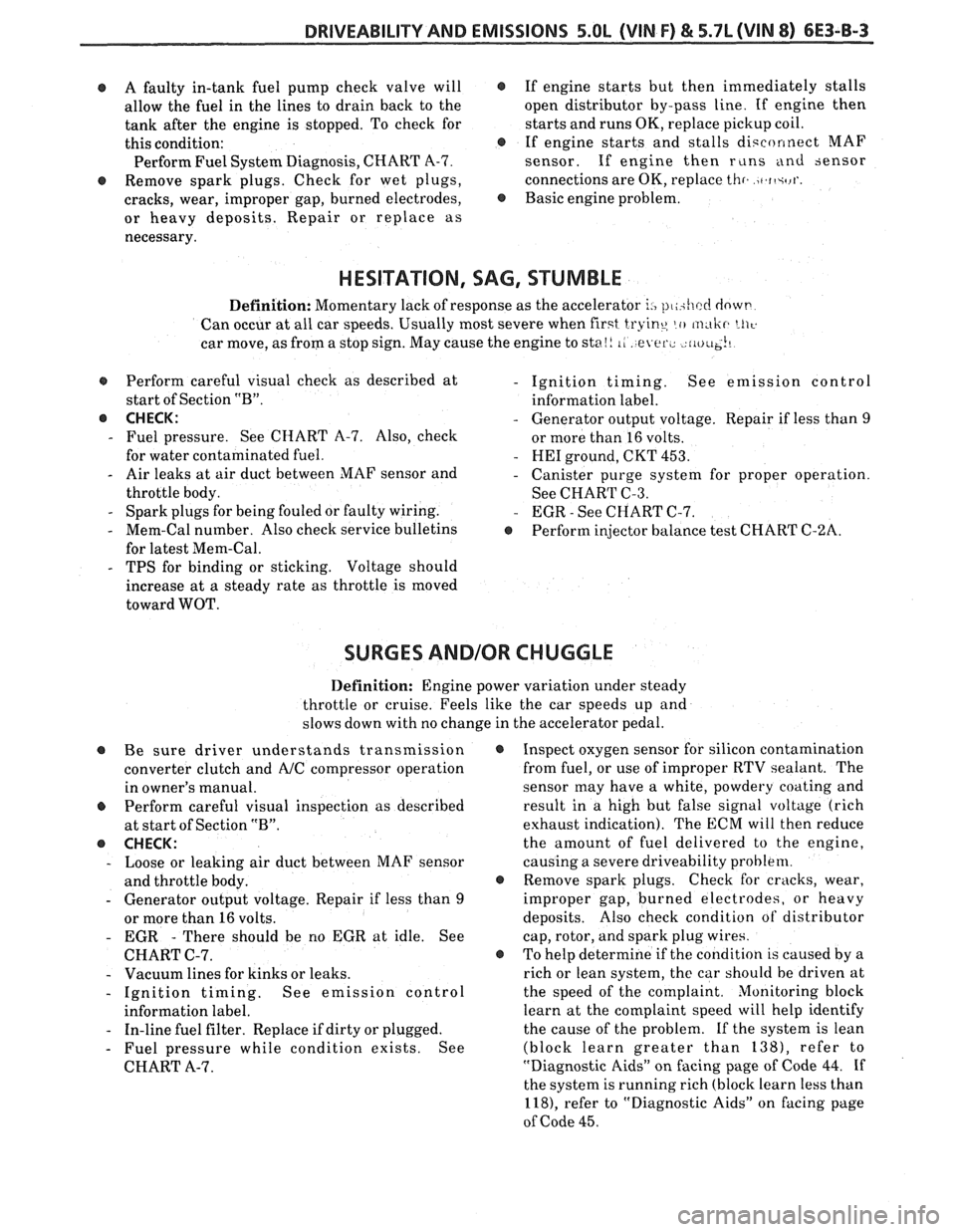
DRIVEABILITY AND EMISSIONS 5.OL (VIN F) & 5.7L (VIN 8) 6E3-8-3
@ A faulty in-tank fuel pump check valve will @
allow the fuel in the lines to drain back to the
tank after the engine is stopped. To check for
this condition:
e
Perform Fuel System Diagnosis, CHART A-7.
@ Remove spark plugs. Check for wet plugs,
cracks, wear, improper gap, burned electrodes,
@
or heavy deposits. Repair or replace as
necessary. If
engine starts but then immediately stalls
open distributor by-pass line. If engine then
starts and runs OK, replace pickup coil.
If engine starts and stalls disconnect MAF
sensor. If engine then
r~lns and sensor
connections are OK, replace
thr. )t.ft+rl'.
Basic engine problem.
HESITATION, SAG, STUMBLE
Definition: Momentary lack of response as the accelerator i., pl,ihcc! dowt-
Can occur at all car speeds. Usually most severe when first tryine, lo m,tlir. LII~.
car move, as from a stop sign. May cause the engine to sta!! 1, e er., riu~~~!~
s Perform careful visual check as described at
start of Section
"B".
@ CHECK:
- Fuel pressure. See CHART A-7. Also, check
for water contaminated fuel.
- Air leaks at air duct between MAF sensor and
throttle body.
- Spark plugs for being fouled or faulty wiring.
- Mem-Cal number. Also check service bulletins
for latest Mem-Cal.
- TPS for binding or sticking. Voltage should
increase at
a steady rate as throttle is moved
toward WOT.
- Ignition timing. See emission control
information label.
- Generator output voltage. Repair if less than 9
or more than 16 volts.
- HE1 ground, CKT 453.
- Canister purge system for proper operation.
See CHART C-3.
- EGR - See CHART C-7.
e Perform injector balance test CHART C-2A.
SURGES AND/OR CHUGGLE
Definition: Engine power variation under steady
throttle or cruise. Feels like the car speeds up and
slows down with no change in the accelerator pedal.
@ Be sure driver understands transmission
converter clutch and
AJC compressor operation
in owner's manual.
Perform careful visual inspection as described
at start of Section
"B".
e CHECK:
- Loose or leaking air duct between MAF sensor
and throttle body.
- Generator output voltage. Repair if less than 9
or more than 16 volts.
- EGR - There should be no EGR at idle. See
CHART C-7.
- Vacuum lines for kinks or leaks.
- Ignition timing. See emission control
information label.
- In-line fuel filter. Replace if dirty or plugged.
- Fuel pressure while condition exists. See
CHART A-7.
@ Inspect oxygen sensor for silicon contamination
from fuel, or use of improper RTV sealant. The
sensor may have a white, powdery coating and
result in a high but false signal voltage (rich
exhaust indication). The ECM will then reduce
the amount of fuel delivered to the engine,
causing a severe driveability problem.
@ Remove spark plugs. Check for cracks, wear,
improper gap, burned electrodes, or heavy
deposits. Also check condition of distributor
cap, rotor, and spark plug wires.
@ To help determine if the condition is caused by a
rich or lean system, the car should be driven at
the speed of the complaint. Monitoring block
learn at the complaint speed will help identify
the cause of the problem.
If the system is lean
(block learn greater than
1381, refer to
"Diagnostic Aids"
on facing page of Code 44. If
the system is running rich (block learn less than
1181, refer to "Diagnostic Aids" on facing page
of Code
45.