ignition coil PONTIAC FIERO 1988 Service Owner's Guide
[x] Cancel search | Manufacturer: PONTIAC, Model Year: 1988, Model line: FIERO, Model: PONTIAC FIERO 1988Pages: 1825, PDF Size: 99.44 MB
Page 870 of 1825
DRIVEABILITY AND EMISSIONS S.OL (VIN F) & 5.7L (VIN 8) 6E3-B-5
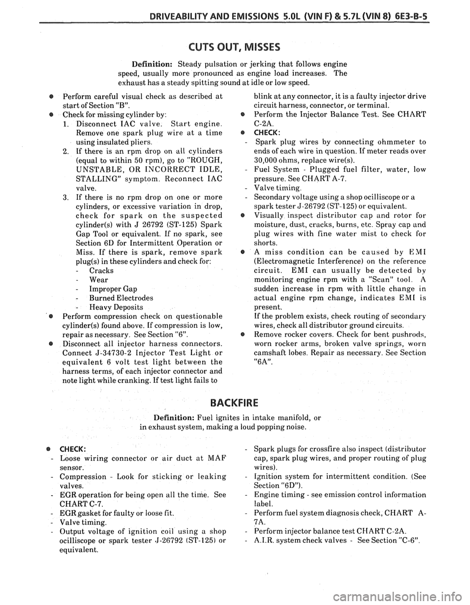
Definition: Steady pulsation or jerking that follows engine
speed, usually more pronounced as engine load increases. The
exhaust has
a steady spitting sound at idle or low speed.
@ Perform careful visual check as described at blink
at any connector, it is a faulty injector drive
start of Section
"B". circuit harness, connector, or terminal.
@ Check for missing cylinder by: @ Perform the Injector Balance Test. See CHART
1. Disconnect IAC valve. Start engine. C-2A.
Remove one spark plug wire at a time
@ CHECK:
using insulated pliers. - Spark plug wires by connecting ohmmeter to
2. If there is an rpm drop on all cylinders ends
of each wire in question. If meter reads over
(equal to within
50 rpm), go to "ROUGH, 30,000
ohms, replace wire(s).
UNSTABLE, OR INCORRECT IDLE, - Fuel System - Plugged fuel filter, water, low
STALLING" symptom. Reconnect IAC pressure. See CHART A-7.
valve.
- Valve timing.
3. If there is no rpm drop on one or more - Secondary voltage using a shop ocilliscope or a
cylinders, or excessive variation in drop, spark tester 5-26792 (ST-125)
or equivalent.
check for spark on the suspected
@ Visually inspect distributor cap and rotor for
cylinder(s) with J 26792 (ST-125) Spark moisture, dust, cracks, burns, etc. Spray cap and
Gap Tool or equivalent. If no spark, see plug wires with fine water mist to check for
Section 6D for Intermittent Operation or shorts.
Miss. If there is spark, remove spark
@ A miss condition can be caused by EM1
plug(s) in these cylinders and check for: (Electromagnetic Interference) on the reference
- Cracks circuit. EM1 can usually be detected by
- Wear monitoring engine rpm with a "Scan" tool. A
- Improper Gap sudden
increase in rpm with little change in
- Burned Electrodes actual engine rpm change, indicates EM1 is
- Heavy Deposits present.
@ Perform compression check on questionable If
the problem exists, check routing of secondary
cylinder(s) found above. If compression is low, wires, check
all distributor ground circuits.
repair as necessary. See Section
"6". @ Remove rocker covers. Check for bent pushrods,
@ Disconnect all injector harness connectors. worn
rocker arms, broken valve springs, worn
Connect
5-34730-2 Injector Test Light or camshaft
lobes. Repair as necessary. See Section
equivalent 6 volt test light between the
"6A".
harness terms, of each injector connector and
note light while cranking. If test light fails to
BACKFIRE
Definition: Fuel ignites in intake manifold, or
in exhaust system, making a loud popping noise.
@ CHECK: - Spark plugs for crossfire also inspect (distributor
- Loose wiring connector or air duct at MAF
cap, spark plug wires, and proper routing of plug
sensor. wires).
- Compression - Look for sticking or leaking - Ignition system for intermittent condition. (See
valves. Section
"6D").
- EGR operation for being open all the time. See - Engine timing - see emission control information
CHART C-7. label.
- EGR gasket for faulty or loose fit. - Perform fuel system diagnosis check, CHART A-
- Valve timing. 7A.
- Output voltage of ignition coil using a shop - Perform injector balance test CI-IART C-2A.
ocilliscope or spark tester 5-26792 (ST-125) or
- A.I.R. system check valves - See Section "C-6".
equivalent.
Page 879 of 1825
6E3-C1-4 5.0L (VIN F) & 5.7L(VIN 8) DRIVEABILITY AND EMISSIONS
See Section "8A" for more information on the PIN
switch, which is part of the neutrallstart and backup
light switch assembly.
NC "ON" Signal
This signal tells the ECM that the NC selector
switch is turned "ON", and that the pressure cycling
switch is closed. The
ECM uses this to adjust the idle
speed when the air conditioning is working.
[f this signal is not available to the ECM, idle may
be rough, especially when the NC compressor cycles.
The voltage at ECM terminal "B8" should equal
battery voltage on a
C60 system and about 5 volts on a
C68 option, when
NC is requested and the pressure
cycling switch is closed.
Distributor Reference Signal
The distributor sends a signal to the ECM to tell it
both engine rpm and crankshaft position. See ignition
system Section
"C4" for further information.
DIAGNOSIS
To read the codes, use a "Scan" tool or ground the
diagnostic terminal with the engine not running and
the ignition "ON". The "Service Engine Soon" light
will flash Code 12 three times and then flash each code
stored in memory three times. All codes stored in
memory would have been read when Code 12 was
flashed again. No new codes can be stored when in the
diagnostics mode (diagnostics lead grounded). This
eliminates confusion while the system is being worked
on.
To clear the codes from memory:
@ Ignition "OFF".
@ Disconnect battery pigtail, located near the
battery, for 30 seconds.
Since the ECM can have a failure which may
affect only one circuit, following the diagnostic
procedures in this section will determine which circuit
has a problem and where it is.
If a diagnostic chart indicates that the
ECM
connections or ECM is the cause of a problem,and the
ECM is replaced, but does not correct the problem, one
of the following may be the reason:
-
@ There is a problem with the ECM terminal
connections.
- The diagnostic chart will say ECM
connections or ECM. The terminals may have to
be removed from the connector in order to check
them properly.
@ The ECM, or Mem-Cal is not correct for the
application.
- The incorrect components may cause
a malfunction and
may or may not set u code.
@ The problem is intermittent. - 'l'his means that the
problem is not present at the time the system is
being checked. In
this case, refer to the "Symptoms" portion
of the
manual and make a careful physical inspection
of
all portions of the system involved.
@ Shorted solenoid, relay coil, or harness. - Solenoids
and relays are turned
"ON" and "OFF" by the
ECM, using internal electronic switches called
"Drivers".
A shorted solenoid, relay coil, or harness in a
GMP4 computer will not damage the ECM,
but will cause the circuit and controlled
component to be inoperative. When the
circuit fault is not present or has been
repaired, the
"Quad-Driver" will again
operate in a normal manner due to it's fault
protected design.
If a fault has been repaired
in a circuit controlled by a "Quad-Driver",
the original ECM should be reinstalled and
the circuit checked for proper operation.
ECM replacement will
not be necessary if the
repaired circuit or component now operates
correctly.
534636 or BT 8405 testers or equivalent provide a
fast, accurate means of checking for a shorted coil
or a short to battery voltage.
@ The Mem-Cal may be faulty. - Although these
rarely fail, it operates as part of the ECM.
Therefore, it could be the cause
of the problem.
Substitute a known good Mem-Cal.
@ The replacement ECM may be faulty - After the
ECM is replaced, the system should be rechecked
for proper operation. If the diagnostic chart again
indicates the ECM is the problem, substitute a
known good ECM. Although this is a rare
condition, it could happen.
ECM
A faulty ECM will be determined in the diagnostic
charts.
MEM-CAL
An incorrect or faulty Mem-Cal, which is part of
the ECM, may set a Code 41 or 52. Also, be sure Mem-
Cal is fully seated and latched in the socket.
ECM INPUTS
A11 of the sensors and input switches can be
diagnosed by the use of
a "Scan" tool. Following is a
short clescription of how the sensors and switches can
he diagnosed
by the use of a "Scan" tool. The "Scan"
can also be used to compare the values for a normal
running engine with the engine you're diagnosing.
Page 907 of 1825
6E3-C2-20 5.0L (VIN F) & 5.7L (WIN 8) DRIVEABILITY AND EMISSIONS
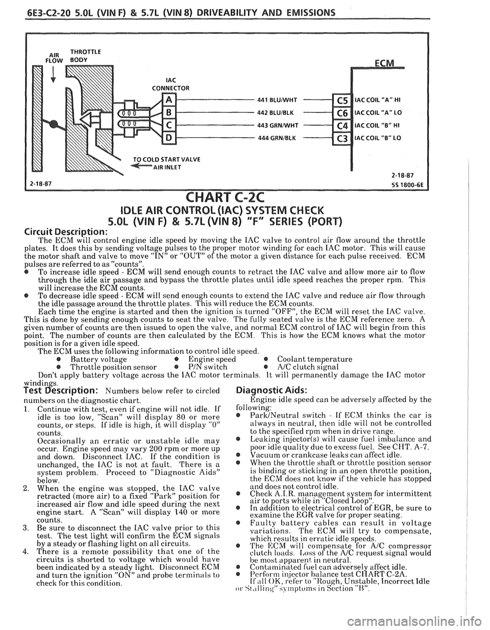
CONNECTOR - 441 BLUMlHT C5 IAC C0lL1'A" HI - 442 BLUIBLK C6 IAC COIL "A" LO - 443 GRNMlHT C4 IAC COIL "B" HI - 444 GRNIBLK C3 lAC COIL "B" LO v
START VALVE
CHART C-2C
IDLE AIR CONTROL (IAC) SYSTEM CHECK
S.OL (VIN F) & 5.7L (VIN 8) "F'" SERIES (PORT)
Circuit Description:
The ECM will control engine idle speed by moving the IAC valve to control air flow around the throttle
plates. It does this by sending voltage pulses to the proper motor winding for each IAC motor. This will cause
the motor shaft and valve to move
"IN" or "OUT" of the motor a given distance for each pulse received. ECM
pulses are referred to as "counts".
@ To increase idle speed - ECM will send enough counts to retract the IAC valve and allow more air to flow
through the idle air passage and bypass the throttle plates until idle speed reaches the proper rpm. This
will increase the ECM counts.
e To decrease idle speed - ECM will send enough counts to extend the IAC valve and reduce air flow through
the idle passage around the throttle plates. This will reduce the ECM counts.
Each time the engine is started and then the ignition is turned "OFF", the ECM will reset the IAC valve.
This is done by sending enough counts to seat the valve.
The fully seated valve is the ECM reference zero. A
given number of counts are then issued to open the valve, and normal ECM control of IAC will begin from this
point. The
number of counts are then calculated by the ECM. This is how the ECM knows what the motor
position is for a given idle speed.
The ECM uses the following information to control idle speed.
@ Battery voltage @ Engine speed @ Coolant temperature @ Throttle position sensor @ PIN switch e A/C clutch signal
Don't apply battery voltage across the IAC motor terminals. It will permanently damage the IAC motor
windin s. Test 6escription: Numbers below refer to circled
numbers on the diagnostic chart.
1. Continue with test, even if engine will not idle. If
idle is too low, "Scan" will display 80 or more
counts, or steps. If idle is high, it will display
"0"
counts.
Occasionally an erratic or unstable idle
[nay occur. Engine speed may vary 200 rpm or more up
and down. Disconnect IAC. If the condition is
unchanged, the IAC is not at fault.
There is a
system problem. Proceed to "Diagnostic Aids"
below.
2. When the engine was stopped, the IAC valve
retracted (more air) to
a fixed "Park" position for
increased air flow and idle speed during the next
engine start. A "Scan" will display 140 or more
coiints. 3. Be sure to disconnect the IAC valve prior to this
test.
The test light will confirm the ECM signals
by a steady or flashing light on all circuits.
4. There is a remote possibility that one of the
circuits is shorted to voltage which would have
been indicated by a steady light. Disconnect ECM
and turn the ignition "ON" and probe terminals to
check for this condition.
Diagnostic Aids:
Engine idle speed can be adversely affected by the
following:
@ ParMNeutral switch - If ECM thinks the car is
always in neutral, then idle will not be controlled
to the specified rpm when in drive range.
@ Leaking injector(s) will cause fuel imbalance and
poor idle quality due to excess fuel. See CHT.
A-7. @ Vacuum or crankcase leaks can affect idle. @ Whenthethrottleshaftorthrottlepositionsensor
is binding or sticking in an open throttle position,
the ECM does not know if the vehicle has stopped
and does not control idle.
@ Check A.I.R. management s stem for intermittent
air to orts while in "~losed~oo~". @ In ad&tion to electrical control of EGR, be sure to
examine the EGR valve for proper seating.
@ Faulty battery cables can result in voltage
variations. The ECM will try to compensate,
which results in erratic idle speeds.
@ 'I'he ECM will com ensate for A/C com ressor
clutch loacls. [.ass ofthe NC request sign8 would
he 11lost apparent, in neutral. @ Contalninatecl fuel can adverse1 affect idle. @ Perform i~!jector balance test C~ART C-2A. If ,111 OK, refer to "Rough, Unstable, Incorrect Idle or St ,tllinqW SJ tnptcfinsiin S~'ction "11''.
Page 919 of 1825
6E3-C4-4 5.OL (VIN F) & 5.7L (VIN 8) DRIVEABILITY AND EMISSIONS
"C" /
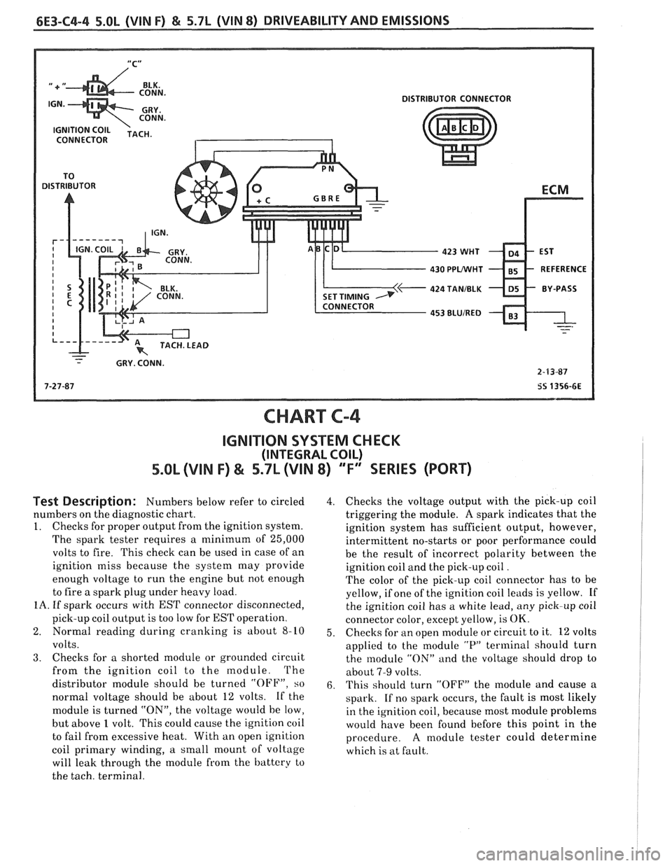
DISTRIBUTOR CONNECTOR
CONNECTOR
430 PPLNVHT
424 TANIBLK
- - - GRY. CONN.
2-F3-87
7-27-87
SS 1356-6E
CHART C-4
IGNITION SYSTEM CHECK
(INTEGRAL COIL)
5.0b (VIN F) & 5.7L (VIN 8) "F" SERIES (PORT)
Test Description: Numbers below refer to circled
numbers on the diagnostic chart.
1. Checks for proper output from the ignition system.
The spark tester requires a minimum of 25,000
volts to fire. This check can be used in case of an
ignition miss because the system may provide
enough voltage to run the engine but not enough
to fire a spark plug under heavy load.
IA. If spark occurs with EST connector disconnected,
pick-up coil output is too low for
EST operation.
2. Normal reading during cranking is about
8-10
volts.
3. Checks for a shorted module or grounded circuit
from the ignition coil to the module. The
distributor module should be turned
"OFF", so
normal voltage should be about 12 volts. If the
module is turned
"ON", the voltage would be low,
but above
1 volt. This could cause the ignition coil
to fail from excessive heat. With an open ignition
coil primary winding,
a small mount of voltage
will leak through the module from the battery to
the tach. terminal.
4. Checks the voltage output with the pick-up coil
triggering the module.
A spark indicates that the
ignition system has sufficient output, however,
intermittent no-starts or poor performance could
be the result of incorrect polarity between the
ignition coil and the pick-up coil
.
The color of the pick-up coil connector has to be
yellow, if one of the ignition coil leads is yellow. If
the ignition coil has a white lead, any pick-up coil
connector color, except yellow, is
OK.
5. Checks
for an open module or circuit to it. 12 volts
applied to the module
"P" terminal should turn
the module
"ON" and the voltage should drop to
about
7-9 volts.
6. This should turn "OFF" the module and cause a
spark. If no spark occurs, the fault is most likely
in the ignition coil, because most module problems
would have been found before this point in the
procedure.
A module tester could determine
which is at fault.
Page 959 of 1825
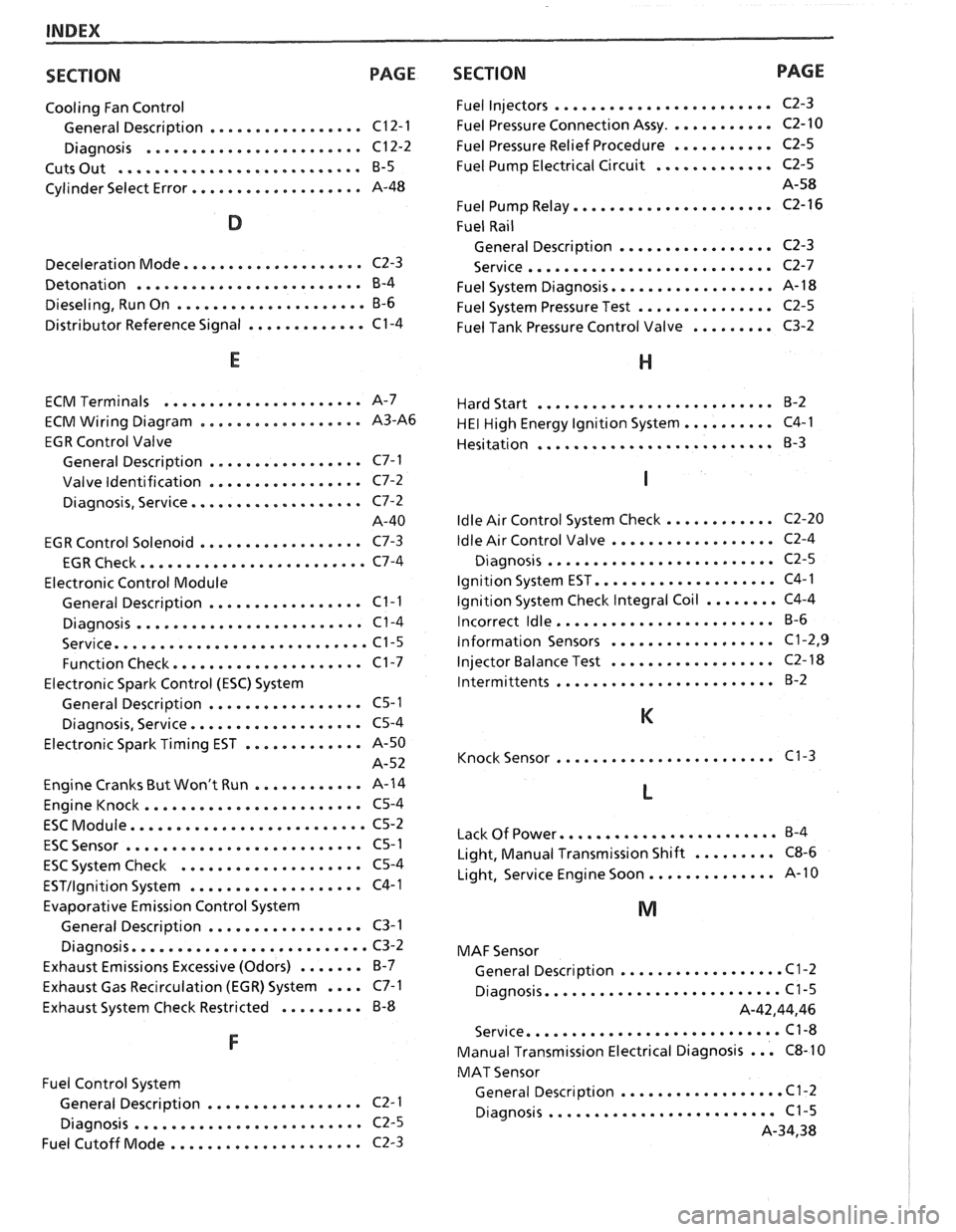
INDEX
SECTION PAGE
Cooling Fan Control
................. General Description C12-1
........................ Diagnosis C12-2
........................... Cuts Out B-5
................... Cylinder Select Error A-48
.................... Deceleration Mode C2-3
......................... Detonation B-4
..................... Dieseling. Run On B-6
............. Distributor Reference Signal C1-4
...................... ECM Terminals A-7
.................. ECM Wiring Diagram A3-A6
EGR Control Valve
................. General Description C7-1
................. Valve Identification C7-2
................... Diagnosis. Service C7-2
A-40
.................. EGR Control Solenoid C7-3
......................... EGR Check C7-4
Electronic Control Module
................. General Description C1-1
......................... Diagnosis C1-4
............................ Service C1-5
..................... Function Check C1-7
Electronic Spark Control (ESC) System
................. General Description C5-1
................... Diagnosis. Service C5-4
Electronic Spark Timing EST
............. A-50
A-52
Engine Cranks But Won't Run
............ A-14
........................ Engine Knock C5-4
.......................... ESC Module C5-2
.......................... ESC Sensor C5-1
.................... ESC System Check C5-4
................... ESTllgnition System C4-1
Evaporative Emission Control System
................. General Description C3-1
.......................... Diagnosis C3-2
Exhaust Emissions Excessive (Odors)
....... B-7
Exhaust Gas Recirculation (EGR) System
.... C7-1
Exhaust System Check Restricted
......... B-8
Fuel Control System
................. General Description C2- 1
......................... Diagnosis C2-5
..................... Fuel Cutoff Mode C2-3
SECTION PAGE
Fuel Injectors ........................
Fuel Pressure Connection Assy ............
Fuel Pressure Relief Procedure ...........
Fuel Pump Electrical Circuit .............
Fuel Pump Relay ......................
Fuel Rail
General Description
.................
........................... Service
Fuel System Diagnosis
..................
Fuel System Pressure Test ...............
Fuel Tank Pressure Control Valve .........
.......................... Hard Start B-2
.......... HE1 High Energy Ignition System C4-1
.......................... Hesitation
B-3
............ Idle Air Control System Check C2-20
.................. Idle Air
Control Valve C2-4
......................... Diagnosis C2-5
.................... Ignition System EST C4-1
........ Ignition System Check Integral Coil C4-4
........................ Incorrect Idle B-6
.................. Information Sensors C1.2. 9
.................. Injector
Balance Test C2-18
........................ lntermittents B-2
........................ Knock Sensor C1-3
........................ Lack Of Power B-4
......... Light. Manual Transmission Shift C8-6
.............. Light. Service Engine Soon A-10
MAF Sensor
.................. General Description C1-2
.......................... Diagnosis C1-5
A.42.44. 46
............................ Service C1-8
... Manual Transmission Electrical Diagnosis C8-10
MAT Sensor
.................. General Description C1-2
......................... Diagnosis C1-5
A.34. 38
Page 973 of 1825
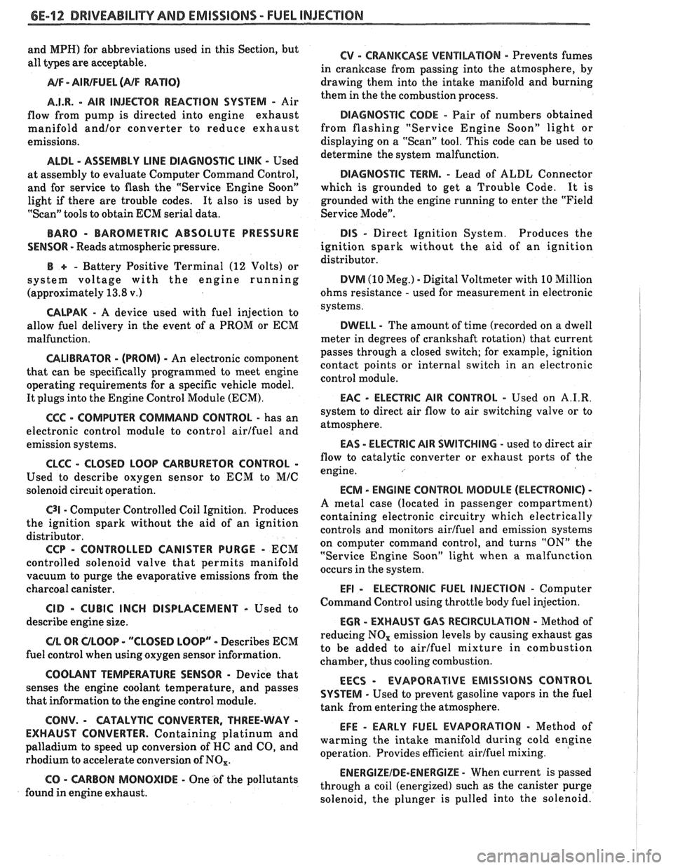
6E-12 DRIVEABILITY AND EMISSIONS - FUEL INJECUION
and MPH) for abbreviations used in this Section, but
all types are acceptable.
NA/F - AI WFUEL (NF RATIO)
A.I.R.
- AIR INJECTOR REACTION SYSTEM - Air
flow from pump is directed into engine exhaust
manifold
and/or converter to reduce exhaust
emissions.
ALDL - ASSEMBLY LINE DIAGNOSTIC LINK - Used
at assembly to evaluate Computer Command Control,
and for service to flash the "Service Engine Soon"
light
if there are trouble codes. It also is used by
"Scan" tools to obtain ECM serial data.
BARO - BAROMETRIC ABSOLUTE PRESSURE
SENSOR
- Reads atmospheric pressure.
B + - Battery Positive Terminal (12 Volts) or
system voltage with the engine running
(approximately 13.8
v.)
CALPAK - A device used with fuel injection to
allow fuel delivery in the event of a PROM or ECM
malfunction.
CALIBRATOR - (PROM) - An electronic component
that can be
specifically programmed to meet engine
operating requirements for a
specific vehicle model.
It plugs into the Engine Control Module
(ECM).
CCC - COMPUTER COMMAND CONTROL - has an
electronic control module to control airlfuel and
emission systems.
CLCC - CLOSED LOOP CARBURETOR CONTROL -
Used to describe oxygen sensor to ECM to MIC
solenoid circuit operation.
C3I - Computer Controlled Coil Ignition. Produces
the ignition spark without the aid of an ignition
distributor.
CCP - CONTROLLED CANISTER PURGE - ECM
controlled solenoid valve that permits manifold
vacuum to purge the evaporative emissions from the
charcoal canister.
CID - CUBIC INCH DISPLACEMENT - Used to
describe engine size.
UL OR ULOOP - "CLOSED LOOP" - Describes ECM
fuel control when using oxygen sensor information.
COOLANT TEMPERATURE SENSOR - Device that
senses the engine coolant temperature, and passes
that information to the engine control module.
CONV. - CATALYTIC CONVERTER, THREE-WAY -
EXHAUST CONVERTER. Containing platinum and
palladium to speed up conversion of
HC and CO, and
rhodium to accelerate conversion of NO,.
CO - CARBON MONOXIDE - One of the pollutants
found in engine exhaust.
6V - CRANKCASE VENTlhaflON - Prevents fumes
in crankcase from passing into the atmosphere, by
drawing them into the intake manifold and burning
them in the the combustion process.
DIAGNOSTIC CODE - Pair of numbers obtained
from flashing "Service Engine Soon" light or
displaying on a "Scan" tool. This code can be used to
determine the system malfunction.
DIAGNOSTIC TERM. - Lead of ALDL Connector
which is grounded to get a Trouble Code.
It is
grounded with the engine running to enter the "Field
Service Mode".
DIS - Direct Ignition System. Produces the
ignition spark without the aid of an ignition
distributor.
DVM (10 Meg.) - Digital Voltmeter with 10 Million
ohms resistance
- used for measurement in electronic
systems.
DWELL - The amount of time (recorded on a dwell
meter in degrees of crankshaft rotation) that current
passes through a closed switch; for example, ignition
contact points or internal switch in an electronic
control module.
EAC - ELECTRIC AIR CONTROL - Used on A.I.R.
system to direct air flow to air switching valve or to
atmosphere.
EAS - ELECTRIC AIR SWITCHING - used to direct air
flow to catalytic converter or exhaust ports of the
engine.
ECM - ENGINE CONTROL MODULE (ELECTRONIC) -
A metal case (located in passenger compartment)
containing electronic circuitry which electrically
controls and monitors airlfuel and emission systems
on computer command control, and turns
"ON" the
"Service Engine Soon" light when a malfunction
occurs in the system.
EFI - ELECTRONIC FUEL INJECTION - Computer
Command Control using throttle body fuel injection.
EGR - EXHAUST GAP REClRCUbATlON - Method of
reducing NO, emission levels by causing exhaust gas
to be added to airlfuel mixture in combustion
chamber, thus cooling combustion.
EECS - EVAPORATIVE EMISSIONS CONTROL
SYSTEM
- Used to prevent gasoline vapors in the fuel
tank from entering the atmosphere.
EFE - EARLY FUEL EVAPORATION - Method of
warming the intake manifold during cold engine
operation. Provides efficient airlfuel mixing.
ENERGIZEIDE-ENERGIZE - When current is passed
through a coil (energized) such as the canister purge
solenoid, the plunger is pulled into the solenoid.
Page 974 of 1825
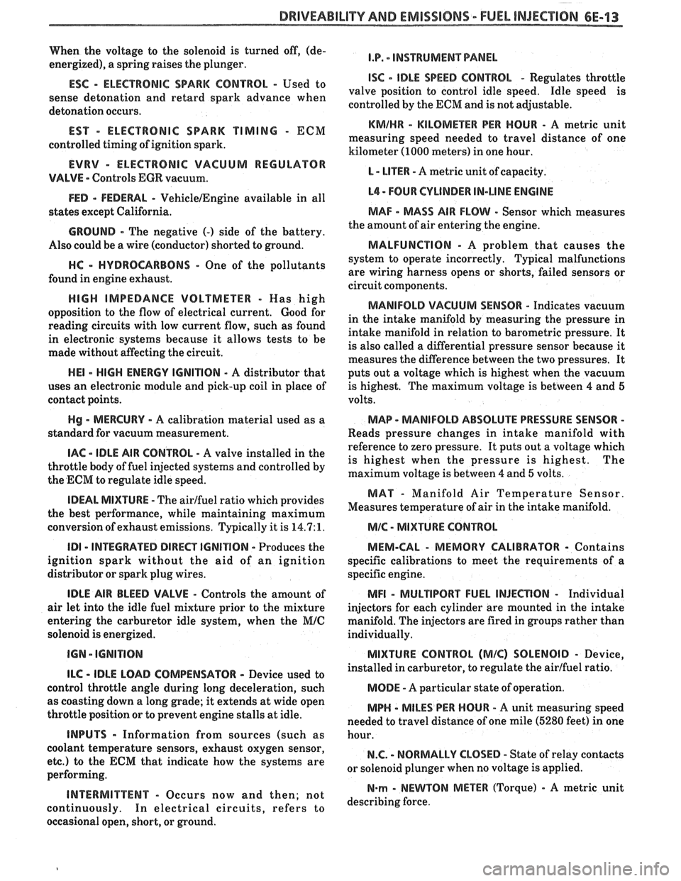
DRIVEABILIW AND EMISSIONS - FUEL INJECTION 6E-13
When the voltage to the solenoid is turned off, (de-
energized), a spring raises the plunger.
ESC - ELECTRONIC SPARK CONTROL - Used to
sense detonation and retard spark advance when
detonation occurs.
EST - ELECTRONIC SPARK TIMING - ECM
controlled timing of ignition spark.
EVRV - ELECTRONIC VACUUM REGULAWR
VALVE - Controls EGR vacuum.
FED - FEDEWL - VehicleIEngine available in all
states except California.
GROUND - The negative (-) side of the battery.
Also could be a wire (conductor) shorted to ground.
HC - HYDROCARBONS - One of the pollutants
found in engine exhaust.
HIGH IMPEDANCE VOLTMETER - Mas high
opposition to the flow of electrical current.
Good for
reading circuits with low current flow, such as found
in electronic systems because it allows tests to be
made without affecting the circuit.
HE1 - HIGH ENERGY IGNITION - A distributor that
uses an electronic module and pick-up coil in place of
contact points.
Hg - MERCURY - A calibration material used as a
standard for vacuum measurement.
IAC - IDLE AIR CONTROL - A valve installed in the
throttle body of fuel injected systems and controlled by
the ECM to regulate idle speed.
IDEAL MIXWRE - The airlfuel ratio which provides
the best performance, while maintaining maximum
conversion of exhaust emissions. Typically it is
14.7:1.
ID1 - INTEGRATED DIRECT IGNITION - Produces the
ignition spark without the aid of an ignition
distributor or spark plug wires.
IDLE AIR BLEED VALVE - Controls the amount of
air let into the idle fuel mixture prior to the mixture
entering the carburetor idle system, when the
MIC
solenoid is energized.
ILC - IDLE LOAD COMPENSATOR - Device used to
control throttle angle during long deceleration, such
as coasting down a long grade; it extends at wide open
throttle position or to prevent engine stalls at idle.
INPUTS - Information from sources (such as
coolant temperature sensors, exhaust oxygen sensor,
etc.) to the ECM that indicate how the systems are
performing.
INTERMITTENT - Occurs now and then; not
continuously. In electrical circuits, refers to
occasional open, short, or ground.
I.P. - INSTRUMENT PANEL
ISC - IDLE SPEED CONTROL - Regulates throttle
valve position to control idle speed. Idle speed is
controlled by the ECM and is not adjustable.
KMIHR - KILOMEnR PER HOUR - A metric unit
measuring speed needed to travel distance of one
kilometer (1000 meters) in one hour.
L - LITER - A metric unit of capacity.
L4 - FOUR CYLINDER IN-LINE ENGINE
MAF - MASS AIR FLOW - Sensor which measures
the amount of air entering the engine.
MALFUNCTION - A problem that causes the
system to operate incorrectly. Typical malfunctions
are wiring harness opens or shorts, failed sensors or
circuit components.
MANIFOLD VACUUM SENSOR - Indicates vacuum
in the intake manifold by measuring the pressure in
intake manifold in relation to barometric pressure. It
is also called a differential pressure sensor because
it
measures the difference between the two pressures. It
puts out a voltage which is highest when the vacuum
is highest. The maximum voltage is between 4 and 5
volts.
MAP - MANIFOLD ABSOLUTE PRESSURE SENSOR -
Reads pressure changes in intake manifold with
reference to zero pressure. It puts out a voltage which
is highest when the pressure is highest. The
maximum voltage is between
4 and 5 volts.
MAT - Manifold Air Temperature Sensor.
Measures temperature of air in the intake manifold.
MIC - MIXTURE CONTROL
MEM-CAL
- MEMORY CALIBRATOR - Contains
specific calibrations to meet the requirements of a
specific engine.
MFI - MULTlPORT FUEL INJECnON - Individual
injectors for each cylinder are mounted in the intake
manifold. The injectors are fired in groups rather than
individually.
MIXTURE CONTROL (MIC) SOLENOID - Device,
installed in carburetor, to regulate the airlfuel ratio.
MODE - A particular state of operation.
MPH - MILES PER HOUR - A unit measuring speed
needed to travel distance of one mile (5280 feet) in one
hour.
N.C. - NORMALLY CLOSED - State of relay contacts
or solenoid plunger when no voltage is applied.
N-rn - NEWTON METER (Torque) - A metric unit
describing force.
Page 1179 of 1825
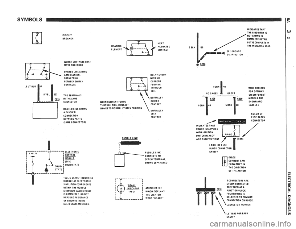
SYMBOLS
CIRCUIT BREAKER
SWITCH CONTACTS THAT
MOVE TOGETHER
DASHED LlNE SHOWS
A MECHANICAL
CONNECTION BETWEEN SWITCH
CONTACTS
~26 IN THE SAME
CONNECTOR
DASHED
LlNE SHOWS
A PHYSICAL
CONNECTION BETWEEN PARTS
(SAME
CONNECTORl
ELECTRONIC
CONTROL
MODULE
(ECM) SOLlO STATE
STATE1 .,, ,,,--=----,-a
"SOLIO STATE" IDENTIFIES
MODULE AS ELECTRONIC.
SIMPLIFIED COMPONENTS
WITHIN THE MOOULE
SHOW HOW EACH CIRCUIT
IS COMPLETED. DO NOT
MEASURE RESISTANCE
OF CIRCUITS
INSIDE SOLlO STATE MODULES. HEAT
HEATING
ACTUATED ELEMENT CONTACT
RELAY SHOWN
WlTH NO
CURRENT FLOWING
THROUGH
COIL
NORMALLY
WHEN CURRENT FLOWS CLOSE0
THROUGH COIL, CONTACT CONTACT
MOVES TO NORMALLY OPEN POSITION
NORMALLY
OPEN
CONTACT
FUSIBLE
LINK
I I
SCREW TERMINAL,
SHOWN SEPARATED
I BAAKE I INDICATOR I AN INDICATOR (RED, ! WHICH DISPLAYS
3 BLK
INDICATES THAT
THE CIRCUITRY IS
NOT SHOWN IN
COMPLETE DETAIL
BUT
IS COMPLETE IN
150 THE INOICATED CELL
SEE GROUND OlSTRlBUTlON
GZOO . -
WlRE CHOICES
FOR OPTIONS
GAGES OR DIFFERENT
SHOWN
AN0 LABELED
COLOR OF
- FUSE BLOCK - - - - - - - . . CONNECTOR
INOICAT / POWER IS SUPPLIED I $ I / WlTH IGNITION SWITCH IN ACCY /' AN0 RUN POSITIONS
LABEL OF FUSE
BLOCK CONNECTOR
CAVITY
DIODE CURRENT CAN
FLOW ONLY IN
N- THE DIRECTION
OF THE ARROW
3 CONNECTORS ARE
SHOWN CONNECTED
TOGETHER AT A
JUNCTION BLOCK.
FOURTH
WIRE IS
SOLDERED TO COMMON
CONNECTION ON BLOCK.
CONNECTOR NUMBER
LETTERS FOR EACH
CAVITY
Page 1211 of 1825
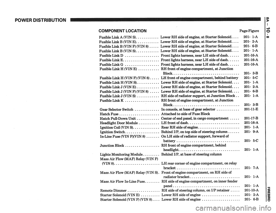
POWER DISTRIBUTION
COMPONENT LOCATlON Page-Figure
Fusible Link A (VIN S)
............ Lower RH side of engine. at Starter Solenoid ....
Fusible Link B (VIN E) ............ Lower RH side of engine. at Starter Solenoid ....
Fusible Link B (VIN F) (VIN 8) ..... Lower RH side of engine. at Starter Solenoid ....
............ Fusible Link B (VIN S) Lower
RH side of engine. at Starter Solenoid ....
Fusible Link D .................. Front lights harness. near LH side of dash ......
Fusible Link E ................... Front lights harness. near LH side of dash ......
Fusible Link G .................. Front lights harness. near LH side of dash ......
Fusible Link H (VIN E) ........... RH front of engine compartment. at Junction
Block
...................................
Fusible Link N (VIN F) (VIN 8) ..... LN front of engine compartment. behind battery
Fusible Link H (VIN S)
............ Lower RH side of engine. at Starter Solenoid ....
J (VIN E) ............ Lower RH side of engine, at Starter Solenoid ....
J (VIN F) (VIN 8) ..... Lower RH side of engine, at Starter Solenoid ....
J (VIN S) ............ RH side of radiator support. at Junction Block ..
.................. Fusible Link K RN front of engine compartment. at Junction
Block
...................................
Gear Selector Switch ............. In console, at base of gear selector ............
Hatch Fuse ..................... Attached to side of Fuse Block
Hatch Pull-Down Unit
............ Center of end panel, in cargo compartment .....
Headlight Door Module ........... LH front of dash ...........................
Ignition Coil (VIN S) .............. Rear RH side of engine ......................
Ignition Switch .................. Behind IIP. on top side of steering column ......
In-Line Fuse (VIN F)(VIN 8) ....... On LH side of radiator support. forward of
................................. battery
.................. Junction Block RH front of engine compartment. behind
................................ headlight
Lights Monitoring Module
......... Behind IIP. at base of steering column
Mass Air Flow (MAF) Relay (VIN
F)
........................ (VIN 8) LH rear corner of engine compartment, on relay
................................. bracket
Mass Air Flow (MAF) Relay (VIN S)
. Front of engine compartment. on RH side of
radiator bracket
..........................
Mass Air Flow In-Line Fuse ........ RN side of engine compartment, on inner fender
panel
...................................
Remote Dimmer ................. RH side of steering column. on IIP retainer .....
Starter Solenoid (VIN E) .......... Lower RH side of engine ....................
Starter Solenoid (VIN F) (VIN 8) .... Lower RH side of engine ....................
Page 1250 of 1825
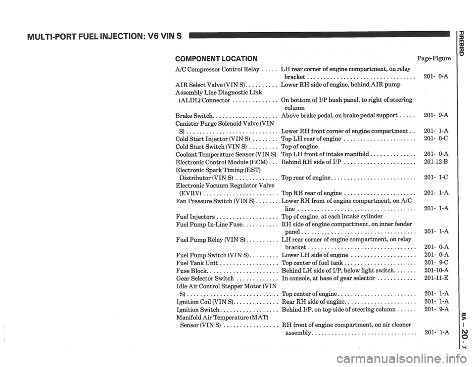
MULTI-PORT FUEL INJECTION: V6 VIN S
COMPONENT LOCATION
AIC Compressor Control Relay ..... LH rear corner of engine compartment, on relay
................................. bracket
AIR Select Valve (VIN S)
.......... Lower RN side of engine, behind AIR pump
Assembly Line Diagnostic Link
(ALDL) Connector
.............. On bottom of IIP hush panel, to right of steering
column
Brake Switch.
................... Above brake pedal, on brake pedal support .....
Canister Purge Solenoid Valve (VIN
............................ .. S) Lower RH front
corner of engine compartment
Cold Start Injector (VIN S)
........ Top LH rear of engine ......................
Cold Start Switch (VIN S) ......... Top of engine
Coolant Temperature Sensor (VIN S) Top LN front of intake manifold.
.............
Electronic Control Module (ECM) ... Behind RH side of IIP ......................
Electronic Spark Timing (EST)
......................... Distributor (VIN S) ............. Top rear of engine.
Electronic Vacuum Regulator Valve
(EVRV)
....................... TopRHrearofengine ......................
Fan Pressure Switch (VIN S) ....... Lower RH front of engine compartment, on AIC
line ....................................
Fuel Injectors ................... Top of engine, at each intake cylinder
Fuel Pump In-Line Fuse.
.......... RH side of engine compartment, on inner fender
panel
...................................
Fuel Pump Relay (VIN S) .......... LH rear corner of engine compartment, on relay
................................. bracket
Fuel Pump Switch (VIN S)
......... Lower LH side of engine ....................
Fuel Tank Unit .................. Top center of fuel tank ......................
Fuse Block. ..................... Behind LH side of IIP, below light switch. ......
Gear Selector Switch ............. In console, at base of gear selector ............
Idle Air Control Stepper Motor (VIN
S)
............................ Topcenterofengine ........................
Ignition Coil (VIN S). ............. Rear RH side of engine. .....................
Ignition Switch. ................. Behind IIP, on top side of steering column ......
Manifold Air Temperature (MAT)
................. Sensor (VIN S) RH front of engine compartment, on air cleaner
............................... assembly. Page-Figure