fuel cap PONTIAC FIERO 1988 Service Repair Manual
[x] Cancel search | Manufacturer: PONTIAC, Model Year: 1988, Model line: FIERO, Model: PONTIAC FIERO 1988Pages: 1825, PDF Size: 99.44 MB
Page 10 of 1825
GENERAL INFORMATION OA-7
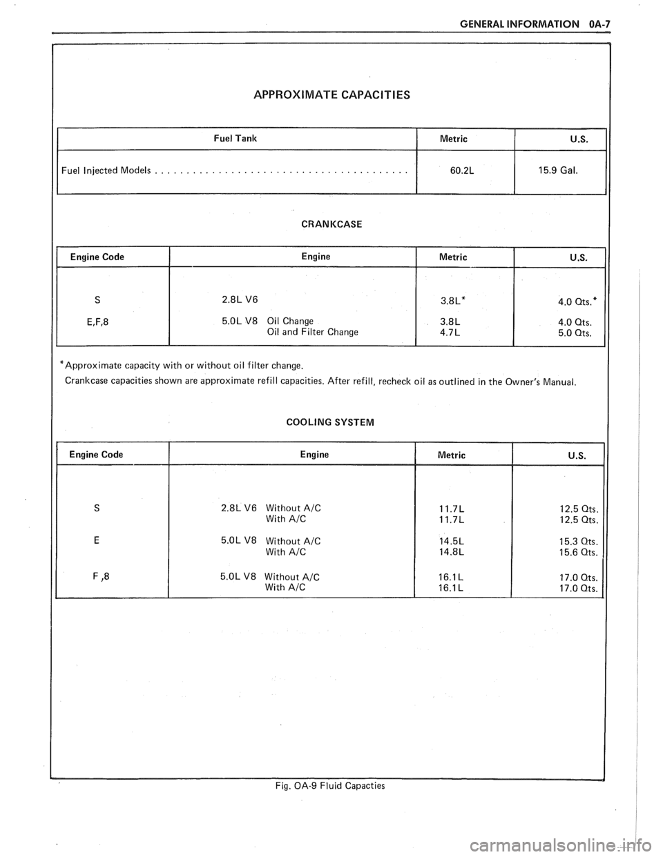
APPROXIMATE CAPACITIES
Fuel Injected Models . . . . . . . . . . . . . . . . . . . . . . . . . . . . . . . . . . . . . . . .
CRANKCASE
5.OL V8 Oil Change
*Approximate capacity with or without oil filter change.
Crankcase capacities shown are approximate refill capacities. After refill, recheck oil as outlined in the Owner's Manual.
COOLING SYSTEM
2.8L V6 Without A/C
5.OL V8 Without A/C
Fig. OA-9 Fluid Capacties
Page 20 of 1825
F CARLINE
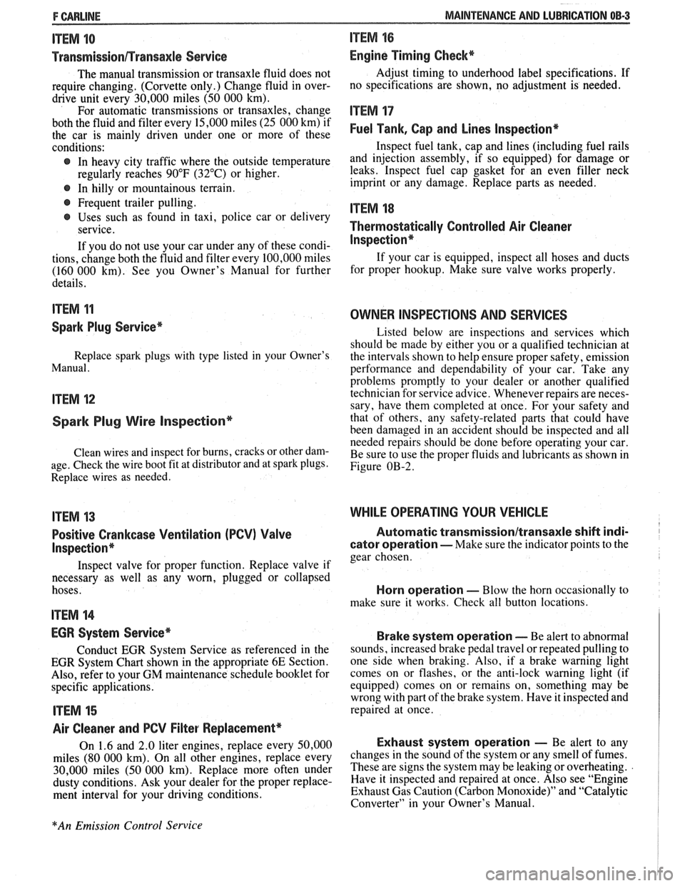
ITEM 10
TransmissionRransaxle Service
The manual transmission or transaxle fluid does not
require changing. (Corvette only.) Change fluid in over-
drive unit every 30,000 miles (50 000 km).
For automatic transmissions or transaxles, change
both the fluid and filter every 15,000 miles (25 000 km) if
the car is mainly driven under one or more of these
conditions:
@ In heavy city traffic where the outside temperature
regularly reaches 90°F (32°C) or higher.
@ In hilly or mountainous terrain.
@ Frequent trailer pulling.
@ Uses such as found in taxi, police car or delivery
service.
If you do not use your car under any of these condi-
tions, change both the fluid and filter every 100,000 miles
(160 000 km). See you Owner's Manual for further
details.
ITEM 11
Spark Plug Service*
Replace spark plugs with type listed in your Owner's
Manual.
ITEM 12
Spark Plug Wire Inspection*
Clean wires and inspect for burns, cracks or other dam-
age. Check the wire boot fit at distributor and at spark plugs.
Replace wires as needed.
ITEM 13
Positive Crankcase Ventilation (PCV) Valve
Inspection*
Inspect valve for proper function. Replace valve if
necessary as well as any worn, plugged or collapsed
hoses.
ITEM 14
EGR System Service*
Conduct EGR System Service as referenced in the
EGR System Chart shown in the appropriate 6E Section.
Also, refer to your GM maintenance schedule booklet for
specific applications.
ITEM 15
Air Cleaner and PCV Filter Replacement*
On 1.6 and 2.0 liter engines, replace every 50,000
miles (80 000 km). On all other engines, replace every
30,000 miles (50 000 km). Replace more often under
dusty conditions. Ask your dealer for the proper replace-
ment interval for your driving conditions.
MAINTENANCE AND LUBRICATION 08-3
ITEM 16
Engine Timing Check*
Adjust timing to underhood label specifications. If
no specifications are shown, no adjustment is needed.
ITEM 17
Fuel Tank, Cap and Lines Inspection*
Inspect fuel tank, cap and lines (including fuel rails
and injection assembly, if so equipped) for damage or
leaks. Inspect fuel cap gasket for an even filler neck
imprint or any damage. Replace parts as needed.
ITEM 18
Thermostatically Controlled Air Cleaner
Inspection*
If your car is equipped, inspect all hoses and ducts
for proper hookup. Make sure valve works properly.
OWNER INSPECTIONS AND SERVICES
Listed below are inspections and services which
should be made by either you or a qualified technician at
the intervals shown to help ensure proper safety, emission
performance and dependability of your car. Take any
problems promptly to your dealer or another qualified
technician for service advice. Whenever repairs are neces-
sary, have them completed at once. For your safety and
that of others, any safety-related parts that could have
been damaged in an accident should be inspected and all
needed repairs should be done before operating your car.
Be sure to use the proper fluids and lubricants as shown in
Figure OB-2.
WHILE OPERATING YOUR VEHICLE
Automatic transmissionltransaxle shift indi-
cator operation - Make sure the indicator points to the
gear chosen.
Horn operation - Blow the horn occasionally to
make sure it works. Check all button locations.
I
Brake system operation -- Be alert to abnormal
sounds, increased brake pedal travel or repeated pulling to
one side when braking. Also, if a brake warning light
comes on or flashes, or the anti-lock warning light (if
equipped) comes on or remains on, something may be
wrong with part of the brake system. Have it inspected and
repaired at once.
Exhaust system operation - Be alert to any
changes in the sound of the system or any smell of fumes.
These are signs the system may be leaking or overheating.
.
Have it inspected and repaired at once. Also see "Engine
Exhaust Gas Caution (Carbon Monoxide)" and "Catalytic
Converter" in your Owner's Manual.
*An Emission Control Service
Page 22 of 1825
MAINTENANCE AND LUBRICATION OB-5
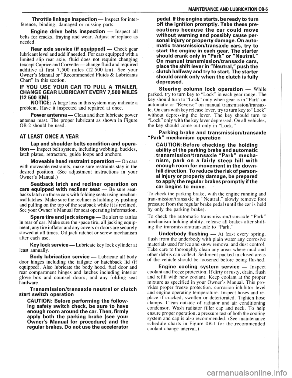
Throttle linkage inspection -- Inspect for inter-
ference, binding, damaged or missing parts.
Engine drive belts inspection - Inspect all
belts for cracks, fraying and wear. Adjust or replace as
needed.
Rear axle service (if equipped) - Check gear
lubricant level and add if needed. For cars equipped with a
limited slip rear axle, fluid does not require changing
(except Caprice and Corvette
- change fluid and required
additive at first
7,500 miles (12 500 km). See your
Owner's Manual or "Recommended Fluids
& Lubricants
Chart" in this section.
IF YOU USE YOUR GAR TO PULL A TRAILER,
CHANGE GEAR LUBRICANT EVERY 7,500 MILES
(12 500 KM).
NOTICE: A large loss in this system may indicate a
problem. Have it inspected and repaired at once.
Power antenna - Clean and then lubricate power
antenna mast. The proper lubricant as shown in Figure
OB-2 should be used.
AT LEAST ONCE A YEAR
Lap and shoulder belts condition and opera-
tion
- Inspect belt system, including webbing, buckles,
latch plates, retractors, guide loops and anchors.
Moveable head restraint operation - On cars
with moveable restraints, make sure restraints stay in the
desired position. (See adjustment instructions in your
Owner's Manual.)
Seatback latch and recliner operation on
cars equipped
with recliner seat --- Be sure seat-
backs latch on those cars with folding seats using mechan-
ical latches. Make sure the recliner is holding by pushing
and pulling on the top of the
seatback while it is reclined.
See your Owner's Manual for seat operating information.
Spare tire and jack storage- Be alert to rattles
in rear of car. Make sure the space tire, all jacking equip-
ment, any tire inflator and any covers or doors are securely
stowed at all times. Oil jack ratchet or screw mechanism
after each use.
Key lock service - Lubricate key lock cylinder at
least annually.
Body lubrication service - Lubricate all body
door hinges including the tailgate or hatchback lid (if
equipped). Also lubricate the body hood, fuel door and
rear compartment hinges and latches including interior
glove box and counsel doors, and any folding seat
hardware.
"Fansmissionltransaxle neutral or clutch
starl switch operation
CAUnON: Before pedorming the follow-
ing safety switch check, be sure to have
enough room around the car. Then, firmly
apply both the parking brake (see your
Owner's Manual for procedure) and the
regular brakes. Do not use the accelerator pedal.
If the engine
starls, be ready to turn
off the ignition promptly. Take these pre-
cautions because the car could move
without warning and possibly cause per-
sonal injury or properly damage. On auto-
matic transmissionltransaxle cars, try to
starl the engine in each gear. The starler
should crank only in "Park" or "Neutral."
On manual transmissionltransaxle cars,
place the
shiR lever in "Neutral," push the
clutch halfway and try to starl. The starler
should crank only when the clutch is fully
depressed.
Steering column lock operation
- While
parked, try to turn key to "Lock" in each gear range. The
key should turn to "Lock" only when gear is in "Park" on
automatic or "Reverse" on manual
transmissionltransax-
le. On cars with key release lever, try to turn key toULock"
without depressing the lever. The key should turn to
"Lock" only with the key lever depressed. On all vehicles,
the key should come out only in "Lock."
Parking brake and transmissionltransaxle
"Park" mechanism operation
CAUT1ON:Before checking the holding
ability of the parking brake and automatic
transmissionltransaxle "Park" mecha-
nism, park on a fairly steep hill with
enough room for movement in the down-
hill direction. To reduce the risk of person-
al injury or property damage, be prepared
to apply the regular brakes promptly if the
car begins to move.
To check the parking brake, with the engine running and
transmission/transaxle in "Neutral." slowly remove foot
pressure from the regular brake pedal (until the car is held
by only the parking brake).
To check the automatic transmissionltransaxle "Park"
mechanism holding ability, release all brakes after shift-
ing the transmissionltransaxle to "Park."
ljnderbody flushing - At least every spring,
tlush from the underbody with plain water any corrosive
materials used for ice and snow removal and dust control.
Take care to thoroughly clean any areas where mud and
other debris can collect.
Sediment packed in closed areas
of the vehicle should be loosened before being flushed.
Engine cooling system service - Inspect
coolant and freeze protection. If dirty or rusty, drain, flush
and refill with new coolant. Keep coolant
at the proper
mixture as specified in your Owner's Manual. This pro-
vides proper freeze protection. corrosion inhibitor level
and engine operating temperature. Inspect hoses and re-
place if cracked. swollen or deteriorated. Tighten hose
clamps. Clean outside of radiator and air conditioning
condensor. Wash radiator filler cap and neck.
To help
ensure proper operation. a pressure test of both the cooling
system and cap is also recommended. (See maintenance
schedule charts in Figure
OB-l for the recommended
coolant change interval.)
Page 234 of 1825
TIRES AND WHEELS 3E-3
METRIC WHEEL NUTS AND STUDS
Some models use metric wheel nuts and wheel
studs. The nut will have the word "metric" stamped on
its face and the stud will have the letter
"M" stamped
into the threaded end. The word "metric" is stamped
on its head.
The thread size of the metric wheel nuts and
wheel studs are
"MI2 x 1.5". These stand for:
M = Metric
12
= Diameter in millimeters
1.5
= Millimeters per thread
If a broken stud is found, see Section 3C (Front
Suspension) or Section 3D (Rear Suspension) for
replacement procedure.
INFLATION OF TIRES
The pressure recommended for any model is
carefully calculated to give a satisfactory ride,
handling, tread life and load carrying capacity.
Tire pressure, with tires cold, (after car has set for
three hours or more, or driven less than one mile)
should be checked monthly or before any extended trip
and set to the specifications on the tire placard located
on rear face of driver's door. Tire inflation pressure is
also given in Section OB.
Valve caps or extensions should be on the valves
to keep dust and water out.
1. For sustained driving at speeds up to 85
mph (140 km/h), in countries where such
speeds are allowed by law, your tires should be set
at the pressures recommended on your tire
placard.
Sustained driving at speeds
faster than
85 mph (140 km/h), where
permitted
by law, is not advised unless
your car has special high speed tires available
from many tire dealers.
2. Tire pressures may increase as much as 6 psi
when hot.
3. Higher
than recommended pressure can cause:
o Hard ride
o Tire bruising or carcass damage
Rapid tread wear at center of tire
4. Lower
than
recommended pressure can cause:
@ Tire squeal on turns
@ Hard steering
o Rapid and uneven wear on the edges of the
tread
Tire rim bruises and rupture
e Tire cord breakage
o High tire temperatures
o Reduced handling
High fuel consumption
5. Unequal pressure on same axle can cause:
Uneven braking
o Steering lead
o Reduced handling
e Swerve on acceleration
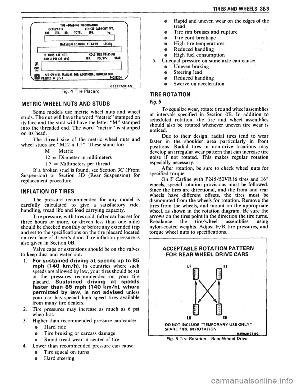
TlRE ROTATION
Fig. 5
To equalize wear, rotate tire and wheel assemblies
at intervals specified in Section OB. In addition to
scheduled rotation, the tire and wheel assemblies
should also be rotated whenever uneven tire wear is
noticed.
Due to their design, radial tires tend to wear
faster in the shoulder area particularly in front
positions. Radial
tires in non-drive
iocations may
develop an irregular wear pattern that can increase tire
noise if not rotated. This makes regular rotation
especially necessary.
After rotation, be sure to check wheel nuts for
specified torque.
On
F Carline with P245/50VR16 tires and 16"
wheels, special rotation provisions must be followed.
Since the tires are directional, and the front and rear
wheels have different offsets, the tires must be
dismounted from the wheels for rotation. Remove the
tires from the wheels, and mount on the appropriate
wheel, as shown in the rotation diagram. Be sure the
arrows on the tires point in the direction the tire turns.
Rebalance the
tire/wheel assemblies using
nylon-coated weights. Adjust
F/R tire pressures, and
torque wheel nuts to specifications.
ACCEPTABLE ROTATION PATTERN
FOR REAR WHEEL
DRIVE GARS
DO NOT INCLUDE "TEMPORARY USE ONLY" SPARE TlRE IN ROTATION
Fig. 5 Tire Rotation - Rear-Wheel Drive
Page 346 of 1825
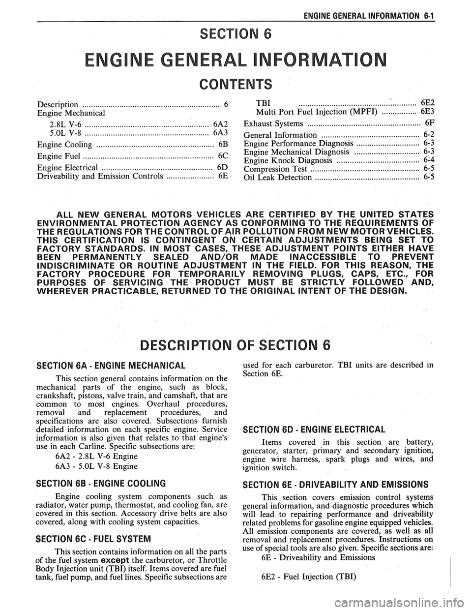
ENGINE GENERAL INFORMATION 6-1
SECTION 6
NE GENERAL NFORMAT
Description ............................................................... 6 TBI ...................................... .. ...... 6E2 ................ Engine Mechanical Multi Port Fuel Injection (MPFI) 6E3 -
............................................... 2.8L V-6 ....................................................... 6A2 Exhaust Systems 6F
5.OL V-8 ......................................................... 6A3 ~~~~~~l ~~f~~~~ti~~ ..................................... 6-2
............................ Engine Cooling ...................................................... 6B Engine Performance Diagnosis 6-3 ............................. Engine Fuel 6C Engine Mechanical Diagnosis
6-3 ........................................................... ................................... Engine Knock Diagnosis 6-4
Engine Electrical ................................................... 6D Compression Test ...................................... ... 6-5
................... Driveability and Emission Controls ...................... 6E Oil Leak Detection .. ..................... 6-5
ALL NEW GENERAL MOTORS VEHICLES ARE CERTIFIED BY THE UNITED STATES
ENVIRONMENTAL PROTECTION AGENCY AS CONFORMING TO THE REQUIREMENTS OF
THE REGULATIONS FOR THE CONTROL OF AIR POLLUTION FROM NEW MOTOR VEHICLES.
THlS CERTIFICATION IS CONTINGENT ON CERTAIN ADJUSTMENTS BEING SET TO
FACTORY STANDARDS. IN MOST CASES, THESE ADJUSTMENT POINTS EITHER HAVE
BEEN PERMANENTLY SEALED AND/OR MADE INACCESSIBLE TO PREVENT
INDISCRIMINATE OR ROUTINE ADJUSTMENT IN THE FIELD. FOR
THlS REASON, THE
FACTORY PROCEDURE FOR TEMPORARILY REMOVING PLUGS, CAPS, ETC., FOR
PURPOSES OF SERVICING THE PRODUCT MUST BE STRICTLY FOLLOWED AND,
WHEREVER PRACTICABLE, RETURNED TO THE ORIGINAL INTENT OF THE DESIGN.
DESCRIPTION OF: SECTION 6
SECTION 6A - ENGINE MECHANICAL used for each carburetor. TBI units are described in
This section general contains information on the Section 6E.
mechanical parts of the engine, such as block,
crankshaft, pistons, valve train, and camshaft, that are
common to most engines. Overhaul procedures,
removal and replacement procedures, and
s~ecifications are also covered. Subsections furnish
detailed information on each specific engine. Service
SECTION 6D - ENG l N E ELECTRICAL
information is also given that relates to that engine's
use in each
Carline. Specific subsections are: Items
covered in this section are battery,
generator, starter, primary and secondary ignition,
6A2
- 2.8L V-6 Engine
engine wire harness, spark plugs and wires, and
6A3
- 5.OL V-8 Engine
ignition switch.
SECTION 6B - ENGINE COOLING
Engine cooling system components such as
radiator, water pump, thermostat, and cooling fan, are
covered in this section. Accessory drive belts are also
covered, along with cooling system capacities.
SECTION 6C - FUEL SYSTEM
This section contains information on all the parts
of the fuel system
except the carburetor, or Throttle
Body Injection unit (TBI) itself. Items covered are fuel
tank, fuel pump, and fuel lines. Specific subsections are
SECTION 6E - DRIVEABILITY AND EMISSIONS
This section covers emission control systems
general information, and diagnostic procedures which
will lead to repairing performance and driveability
related problems for gasoline engine equipped vehicles.
All emission components are covered, as well as all
removal and replacement procedures. Instructions on
use of special tools are also given. Specific sections are:
6E
- Driveability and Emissions
6E2
- Fuel Injection (TBI)
Page 347 of 1825
6-2 ENGINE GENERAL INFORMATION
6E3 - Fuel Injection (Ported) This section has information
on all exhaust
system parts, such as tailpipes, mufflers, and the
SECTION 6F - EXHAUST SYSTEM catalytic converter.
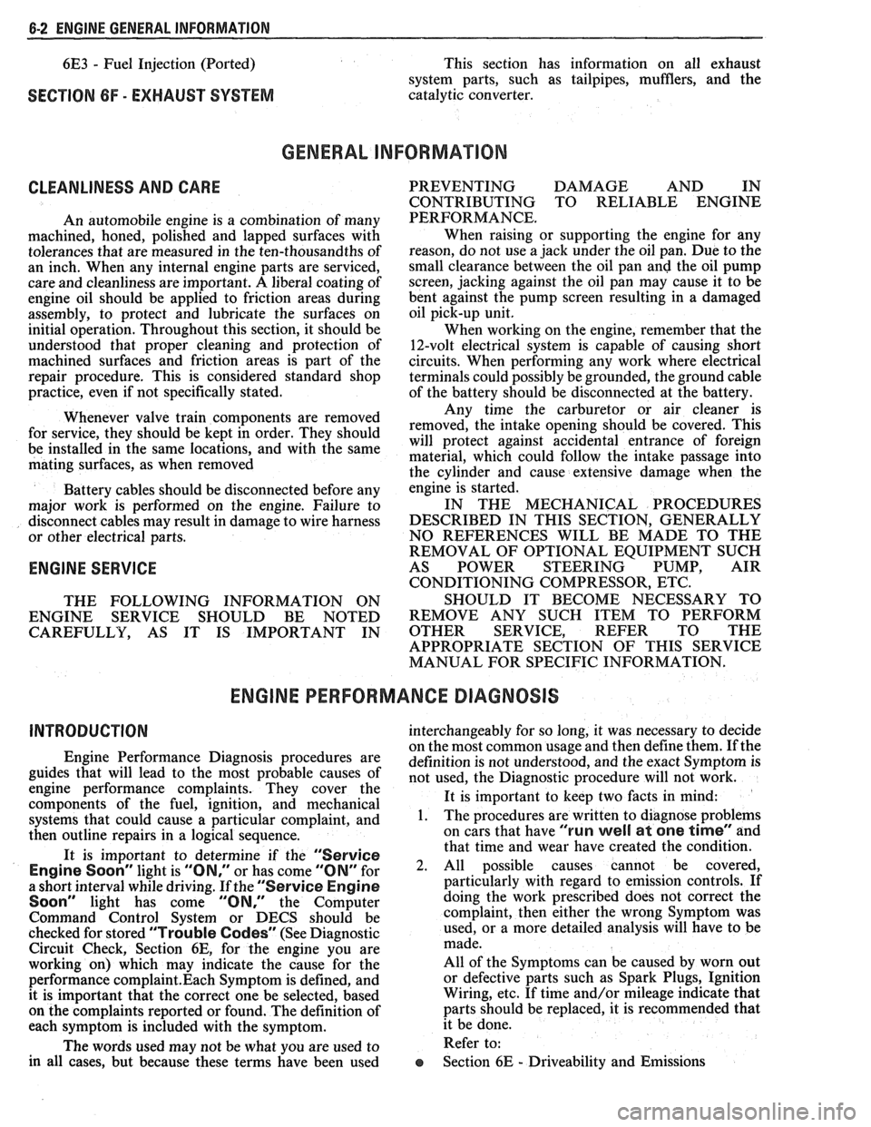
GENERAL INFORMAflION
CLEANLINESS AND CARE
An automobile engine is a combination of many
machined, honed, polished and lapped surfaces with
tolerances that are measured in the ten-thousandths of
an inch. When any internal engine parts are serviced,
care and cleanliness are important. A liberal coating of
engine oil should be applied to friction areas during
assembly, to protect and lubricate the surfaces on
initial operation. Throughout this section, it should be
understood that proper cleaning and protection of
machined surfaces and friction areas is part of the
repair procedure. This is considered standard shop
practice, even if not specifically stated. PREVENTING
DAMAGE AND IN
CONTRIBUTING TO RELIABLE ENGINE
PERFORMANCE.
When raising or supporting the engine for any
reason, do not use a jack under the oil pan. Due to the
small clearance between the oil pan and the oil pump
screen, jacking against the oil pan may cause it to be
bent against the pump screen resulting in a damaged
oil pick-up unit.
When working on the engine, remember that the
12-volt electrical system is capable of causing short
circuits. When performing any work where electrical terminals could possibly be grounded, the ground cable
of the battery should be disconnected at the battery.
Any time the carburetor or air cleaner is
train components are removed removed, the intake opening should be covered. This for service, they should be in order' will protect against entrance of foreign be installed in the same locations, and with the same material, which could follow the intake passage into mating surfaces, as when removed
the cylinder and cause extensive damage when the -
Battery cables should be disconnected before any engin; is started.
major work is performed on the engine. Failure to IN THE MECHANICAL PROCEDURES
disconnect cables may result in damage to wire harness DESCRIBED IN THIS SECTION, GENERALLY
or other electrical parts. NO
REFERENCES WILL BE MADE TO THE
REMOVAL OF OPTIONAL EQUIPMENT SUCH
ENGINE SERVICE AS POWER STEERING PUMP, AIR
CONDITIONING COMPRESSOR, ETC.
THE FOLLOWING INFORMATION ON SHOULD IT BECOME NECESSARY TO
ENGINE SERVICE SHOULD BE NOTED REMOVE ANY SUCH ITEM TO
PERFORM
CAREFULLY, AS IT IS IMPORTANT IN OTHER SERVICE, REFER TO THE
APPROPRIATE SECTION OF THIS SERVICE
MANUAL FOR SPECIFIC INFORMATION.
ENGINE PERFORMANCE DIAGNOSIS
INTRODUCTION interchangeably for so long, it was necessary to decide
on the most common usage and then define them. If the
Engine Performance procedures are definition is not understood, and the exact Symptom is
guides that will lead to the most probable causes of not used, the Diagnostic procedure will not work. engine performance complaints. They cover the
components of the fuel, ignition, and mechanical It
is important to keep two facts in mind:
systems that could cause a particular
complaint, and 1. The procedures are written to diagnose problems
then outline repairs in a logical sequence. on cars
that have
"run well at one time" and
that time and wear have created the condition.
It is important to determine if the
"Service ~~~i~~ soon- light is "ON,~' or has come for 2. All possible causes cannot be covered,
a short interval while driving. If the
"Service Engine particularly with regard to emission controls. If
Soon" light has come "ON," the Computer doing the work prescribed does not correct the
Command Control System or DECS should be complaint, then either the wrong Symptom was
checked for stored
"Trouble Codes" (See Diagnostic used, or a more detailed analysis will have to be
Circuit Check, Section 6E, for the engine you are made.
working on) which may indicate the cause for the All of the Symptoms can be caused by worn out
performance
complaint.Each Symptom is defined, and or defective parts such as Spark Plugs, Ignition
it is important that the correct one be selected, based Wiring, etc. If time and/or mileage indicate that
on the complaints reported or found. The definition of parts should be replaced, it is recommended that
each symptom is included with the symptom. it
be done.
The words used may not be what you are used to Refer to:
in all cases, but because these terms have been used
@ Section 6E - Driveability and Emissions
Page 349 of 1825
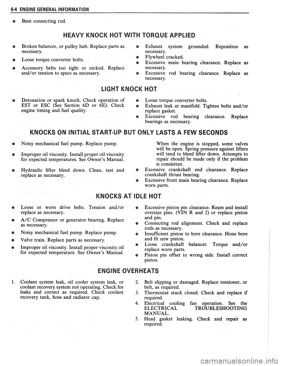
6-4 ENGINE GENERAL INFORMATION
Bent connecting rod.
HEAVY KNOCK H0"FVVI"F TORQUE APPLIED
Broken balancer, or pulley hub. Replace parts as e Exhaust system grounded. Reposition as
necessary. necessary.
Loose torque converter bolts. Flywheel
cracked.
e Excessive main bearing clearance. Replace as
Accessory belts too tight or nicked. Replace
necessary.
and/or tension to specs as necessary.
e Excessive rod bearing clearance. Replace as
necessary.
LIGHT KNOCK HOT
Detonation or spark knock. Check operation of e Loose torque converter bolts.
EST or ESC (See Section
6D or 6E). Check e Exhaust leak at manifold. Tighten bolts and/or
engine timing and fuel quality.
replace gasket.
8 Excessive rod bearing clearance. Replace
bearings as necessary.
KNOCKS ON INITIAL START-UP BUT ONLY LASTS A FEW SECONDS
Noisy mechanical fuel pump. Replace pump.
When the engine is stopped, some valves
will be open. Spring pressure against lifters
Improper oil viscosity. Install proper oil viscosity will
tend to bleed lifter down. Attempts to
for expected temperatures. See Owner's Manual. repair
should be made only if the problem
is consistent.
Hydraulic lifter bleed down. Clean, test and @ Excessive crankshaft end clearance. Replace
replace as necessary. crankshaft
thrust bearing.
@ Excessive front main bearing clearance. Replace
worn parts.
KNOCKS AT IDLE HOT
Loose or worn drive belts. Tension and/or @ Excessive piston pin clearance. Ream and install
replace as necessary. oversize pins. (VIN R and 2) or replace piston
A/C Compressor or generator bearing. Replace and
pin.
as necessary.
e Connecting rod alignment. Check and replace
rods as necessary.
Noisy mechanical fuel pump. Replace pump.
8 Insufficient piston to bore clearance. Hone bore
Valve train. Replace parts as necessary. and
fit new piston.
@ Loose crankshaft balancer. Torque and/or
Improper oil viscosity. Install proper viscosity oil
replace worn parts.
for expected temperature4 See Owner" e Piston pin offset to wrong side. Install correct
ENGINE OVERHEATS
Coolant system leak, oil cooler system leak, or
2. Belt slipping or damaged. Replace tensioner, or
coolant recovery system not operating. Check for belt, as required.
leaks and correct as required. Check coolant
3. Thermostat stuck closed. Check and replace if
recovery tank, hose and radiator cap.
required.
4. Electrical cooling fan operation. See the
ELECTRICAL TROUBLESHOOTING
MANUAL.
5. Head gasket leaking. Check and repair as
required.
Page 352 of 1825
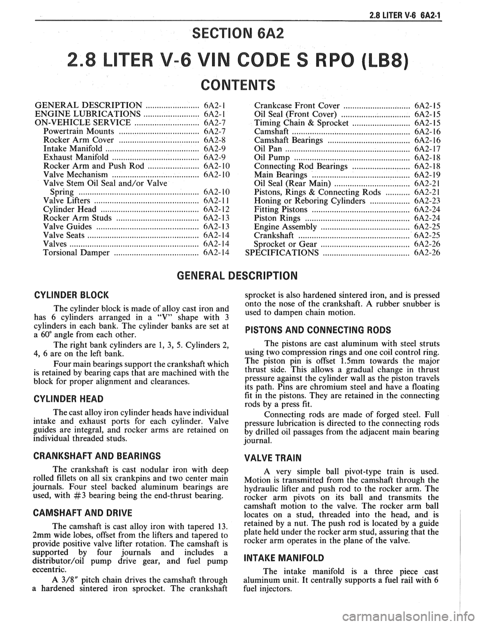
2.8 LITER V-6 BA2-1
TER V-6 V N CODES RPO
CONTENTS
GENERAL DESCRIPTION ........................ 6A2- 1
ENGINE LUBRICATIONS ......................... 6A2- 1
ON-VEHICLE SERVICE ............................. 6A2-7
Powertrain Mounts .................................... 6A2-7
Rocker Arm Cover .................................... 6A2-8
Intake Manifold .......................................... 6A2-9
Exhaust Manifold ................................... 6A2-9
Rocker Arm and Push Rod ....................... 6A2- 10
Valve Mechanism
....................................... 6A2- 10
Valve Stem Oil Seal and/or Valve
Spring
.................... .. .. ... ................... 6A2- 10
Valve Lifters
............................................. 6A2- l l
Cylinder Head ............................................ 6A2- 12
Rocker Arm Studs
.................................... 6A2- 13
Valve Guides
........................................... 6A2- 13
Valve Seats
................................................ 6A2- 14
Valves
......................................................... 6A2- 14
Torsional Damper
..................................... 6A2- 14 Crankcase
Front Cover
.............................. 6A2- 15
Oil Seal (Front Cover)
........................... .... 6A2- 15
Timing Chain
& Sprocket .......................... 6A2- 15
Camshaft
................................................... 6A2- 16
Camshaft Bearings
................................... 6A2- 16
Oil Pan
........................................................ 6A2- 17
Oil Pump
.................................................. 6A2- 18
Connecting Rod Bearings .......................... 6A2- 18
Main Bearings
............................................ 6A2- 19
Oil Seal (Rear Main)
.................................. 6A2-2 1
Pistons, Rings & Connecting Rods ........... 6A2-2 1
Honing or Reboring Cylinders .................. 6A2-23
Fitting Pistons ............................................ 6A2-24
.............................................. Piston Rings 6A2-24
Engine Assembly ...................................... 6A2-25
.................................................. Crankshaft 6A2-25
........................................ Sprocket or Gear 6A2-26
..................................... SPECIFICATIONS 6A2-26
GENERAL DESCRIPTION
CYLINDER BLOCK
The cylinder block is made of alloy cast iron and
has 6 cylinders arranged in a "V" shape with 3
cylinders in each bank. The cylinder banks are set at
a
60" angle from each other.
The right bank cylinders are
1, 3, 5. Cylinders 2,
4, 6 are on the left bank.
Four main bearings support the crankshaft which
is retained by bearing caps that are machined with the
block for proper alignment and clearances.
CYLINDER HEAD
The cast alloy iron cylinder heads have individual
intake and exhaust ports for each cylinder. Valve
guides are integral, and rocker arms are retained on
individual threaded studs.
CRANKSHAFT AND BEARINGS
The crankshaft is cast nodular iron with deep
rolled fillets on all six crankpins and two center main
journals. Four steel backed aluminum bearings are
used, with
#3 bearing being the end-thrust bearing.
CAMSHAFT AND DRIVE
sprocket is also hardened sintered iron, and is pressed
onto the nose of the crankshaft.
A rubber snubber is
used to dampen chain motion.
PISTONS AND CONNECTING RODS
The pistons are cast aluminum with steel struts
using two compression rings and one coil control ring.
The piston pin is offset
1.5mm towards the major
thrust side. This allows a gradual change in thrust
pressure against the cylinder wall as the piston travels
its path. Pins are chromium steel and have a floating
fit in the pistons. They are retained in the connecting
rods by a press fit.
Connecting rods are made of forged steel. Full
pressure lubrication is directed to the connecting rods
by drilled oil passages from the adjacent main bearing
journal.
VALVE TRAIN
A very simple ball pivot-type train is used.
Motion is transmitted from the camshaft through the
hydraulic lifter and push rod to the rocker arm. The
rocker arm
~ivots on its ball and transmits the
camshaft
mot'ion to the valve. The rocker arm ball
locates on a stud, threaded into the head, and is
The camshaft is cast alloy iron with tapered 13. by a nut. The push rod is located by a guide
2mm wide lobes, offset from the lifters and tapered to plate held under the rocker arm stud, assuring that the
provide positive valve lifter rotation. The camshaft is arm Operates in the plane the
support& by four journals and includes a
distributor/oil pump drive gear, and fuel pump INTAKE MANIFOLD - - eccentric.
The intake manifold is a three piece cast
A
3/8" pitch chain drives the camshaft through
aluminum unit. It centrally supports a fuel rail with 6
a hardened sintered iron sprocket. The crankshaft
fuel injectors.
Page 360 of 1825
2.8 LITER V-6 6A2-9
INTAKE MANIFOLD (FIGURE 6A2-7)
Removal
Disconnect battery.
Remove air cleaner.
Drain coolant.
Refer to Section 6E3 for removal of the following
PFI sub-assemblies.
e Plenum
e Fuel Rail
e Runner
Disconnect spark plug wires at spark plugs.
Disconnect wires at coil.
Remove distributor cap and spark plug wires.
Mark distributor position and remove hold down
bracket.
Remove distributor.
Remove air management hose, manual
transmission only.
Disconnect emission canister hoses. Remove pipe
bracket (front left valve cover).
Remove left valve cover.
Remove air management bracket, manual
transmission only.
Remove right valve cover.
Remove upper radiator hose.
Disconnect heater hose.
Disconnect coolant switches.
Remove manifold bolts.
Remove manifold. Discard manifold gaskets and
remove loose RTV from front and rear ridges of
cylinder case.
Installation
When installing intake gaskets, notice that the
gaskets are marked Right Side and Left Side
(carbureted only). Use them only as indicated to
maintain designed efficiency of this engine.
1. Make
sure that no oil or water is present on
surface when new RTV is applied. Place a 5mm
diameter
(3/16") bead of RTV, # 1052917 or
equivalent, on each ridge.
2. Install
new intake gaskets on cylinder heads.
Hold in place by extending ridge RTV bead up
6mm onto the gasket ends. The new intake
gaskets will have to be cut, where indicated, to
install behind push rods. Cut only those areas
that are necessary.
3. Install intake
manifold on engine. Make sure
areas between case ridges and intake are
completely sealed.
4. Install manifold retaining bolts and nuts and
torque in the sequence shown in Figure 6A2-7.
5. Install heater and radiator hose to manifold.
6. Install rocker covers as previously outlined.
7. Connect coolant switches.
8. Install air management bracket.
9. Install pipe bracket (front left rocker cover).
10. Install distributor, distributor cap and retaining
nut. Do not tighten.
11. Refer to Section 6E3 for installation of PFI
sub-assemblies removed. 12.
Connect
necessary wires and hoses.
13. Fill cooling system with
the proper mixture of
ethylene glycol anti-freeze and water. Do not
install radiator cap.
14. Start
engine, set intitial timing. After set, torque
distibutor hold down clamp bolt to 34
N-m (25
lb. ft.). Recheck timing after torquing bolt.
15. Let engine
run until radiator upper hose becomes
hot (thermostat open).
16. With
engine idling, add coolant to radiator, if
necessary, until level reaches bottom of filler
neck.
17. Install
radiator cap, making sure arrows on cap
line up with overflow tube.
Figure 6A2-8 Exhaust Manifold
EXHAUST MANIFOLD (FIGURE 6A2-8)
Removal (Left)
1. Disconnect battery.
2. Raise vehicle.
3. Disconnect exhaust pipe.
4. Remove
(4) rear manifold bolts and (1) nut.
5. Lower vehicle.
6. Disconnect air management, hoses and wires.
7. Remove power steering and fuel line bracket.
8. Remove manifold.
Installation (Left)
1. Clean mating surfaces on manifold and head,
then install manifold in position and install bolts.
2. Torque
manifold bolts to 34
N.m (25 ft. lbs.).
3. Install power steering bracket.
4. Raise vehicle.
5. Install exhaust pipe.
6. Lower vehicle.
7. Connect battery.
Removal (Right)
1. Disconnect battery.
2. Raise vehicle.
3. Disconnect exhaust pipe.
4. Lower vehicle.
Page 376 of 1825
2.8 LITER V-6 6A2-25
Fitting
1. Select rings comparable in size to the piston being
used.
2. Slip
the compression ring in the cylinder bore;
then press the ring down into the cylinder bore
about 6mm above ring travel. Be sure ring is
square with cylinder wall.
3. Measure the space or gap between the ends of the
ring with a feeler gage (Figure
6A2-33).
4. If
the gap between the ends of the ring is below
specifications, remove the ring and try another
for fit.
5. Fit each compression ring to the cylinder in
which it is going to be used.
6. If the pistons have not been cleaned and inspected
as previously outlined, do so.
7. Slip the outer surface of the top and second
compression ring into the respective piston ring
groove and roll the ring entirely around the
groove (Figure
6A2-34). If binding occurs at any
point, the cause should be determined. If there is
a ring groove, remove by dressing with a fine cut
file. If the binding is caused by a distorted ring,
check a new ring.
Installation
1. Install oil ring spacer in groove being sure ends
are butted and not overlapped.
2. Hold
spacer ends butted and install lower steel oil
ring rail.
3. Install upper
steel oil ring rail with gap staggered.
4. Flex
the oil ring assembly to make sure ring is
free. If binding occurs, the cause should be
detemined. If caused by ring groove, remove by
dressing groove with a fine cut file. If binding is
caused by a distorted ring, check a new ring.
5. Install second compression ring. Stagger gap
from other rings.
6. Install top compression ring with gap properly
located.
ENGINE ASSEMBLY
Removal
Disconnect battery.
Remove air cleaner.
Remove hood. Drain radiator.
Remove lower radiator hose.
Remove upper fan shroud.
Remove upper radiator hose and coolant
recovery hose.
Remove transmission cooler lines. Remove radiator.
Remove fan assembly.
Remove heater hoses.
Disconnect carburetor linkage, includes cruise
control detent cable.
Remove vacuum brake booster line.
Remove distributor cap and lay wiring aside.
Disconnect necessary wires and hoses.
Remove power steering pump and lay aside. Raise
vehicle.
Remove exhaust pipes at exhaust manifold.
Remove dust cover.
Remove converter bolts.
Disconnect starter wires.
Remove bell housing bolts.
Remove motor mount through bolts.
Disconnect fuel lines at fuel pump.
Lower vehicle. Support transmission.
Remove
A.I.R./Converter pipes bracket.
Remove engine, include removing wire from
bracket at rear left of engine.
Installation
Position engine assembly in vehicle.
Attach motor mount to engine brackets and
lower engine in place.
Remove engine lifting device.
Remove transmission floor jack.
Raise vehicle on hoist.
Install mount "through" bolts. Torque to
specifications.
Install bell housing bolts. Torque to
specifications.
On vehicles with automatic transmission, install
converter to flywheel attaching bolts. Torque to
specifications.
Install flywheel splash shield of conveter housing
cover as applicable. Torque attaching bolts to
specifications.
Install starter wires.
Connect fuel lines.
Connect exhaust pipe at manifold.
Lower vehicle on hoist.
Reinstall power steering pump, if so equipped.
Connect necessary wires and hoses.
Install radiator and fan shroud and reconnect
radiator and heater hoses.
Fill cooling system.
Fill crankcase with oil. See owner's manual for
specifications.
Install air cleaner.
Install hood.
Connect battery cables.
NOTICE: To avoid possible arcing of battery,
connect positive battery cable first.
22. Start engine, check for leaks and check timing.
CRANKSHAFT
The crankshaft can be removed while the engine
is dissasembled for overhaul, as previously outlined or
without complete disassembly.
Removal
1. With the engine removed from the vehicle,
remove the clutch assembly (if equipped) and
flywheel. Mount engine in stand and clamp
securely.