torque PONTIAC FIERO 1988 Service Repair Manual
[x] Cancel search | Manufacturer: PONTIAC, Model Year: 1988, Model line: FIERO, Model: PONTIAC FIERO 1988Pages: 1825, PDF Size: 99.44 MB
Page 2 of 1825
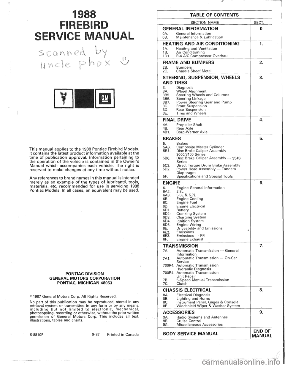
1988
SER
This manual applies to the 1988 Pontiac Firebird Models.
It contains the latest product information available at the
time of publication approval. lnformation pertaining to
the operation of the vehicle is contained in the Owner's
Manual which accompanies each vehicle. The right is
reserved to make changes at any time without notice.
Any references to brand names in this manual is intended
merely as an example of the types of
lubricant% tools,
materials, etc, recommended for use in servicing 1988
Pontiac Models. In all cases, an equivalent may be used.
PONTIAC DIVISION
GENERAL
MOTORS CORPORATION
PONTIAC, MICHIGAN 48053
1987 General Motors Corp. All Rights Reserved.
No part of this publication may be reproduced, stored in any
retrieval system or transmitted in any form or by any means,
including but not limited to electronic, mechanical,
photocopying, recording or otherwise, without the prior written
permission of General Motors Corp. This includes all text,
illustrations, tables and charts.
S-881 OF 9-87 Printed in Canada
TABLE OF CONTENTS
SECTION NAME
GENERAL INFORMATION
OA. General lnformation
OB. Maintenance & Lubrication
1 SECT.
HEATING AND AIR CONDITIONING
1A. Heating and Ventilation
1 B. Air Conditioning
1D1. R-4 AIC Com~ressor Overhaul
FRAME AND BUMPERS
2B. Bumpers 2C. Chassis Sheet Metal
STEERING, SUSPENSION, WHEELS
AND TIRES
3. Diagnosis
3A. Wheel Alignment
3B5. Steering Wheels and Columns 3B6. Steering Linkage 3B7. Power Steering Gear and Pump
3C. Front Suspension
3D. Rear Suspension
3E. Tires and Wheels
FINAL DRIVE
4A. Propeller Shaft
4B. Rear Axle
4B1. Bora-Warner Axle
BRAKES 5. Brakes 5A3. Comoosite Master Cvlinder 5B1. Disc r rake Caliper ~ssembly - 300013100 Series 5B6. Disc Brake Caliper Assembly - 3548
Series
5C3. Direct Torque Drum Brake Assembly 5D2. Power Head Assembly - Tandem Diaohraam 5F. ~~ecifications and Special Tools
ENGINE 6. Engine General lnformation 6A2. 2.8L 6A3. 5.OL & 5.7L 6B. Engine Cooling
6C. En~ine Fuel
6D. ~ngine Electrical 6D1. Battery 6D2. Cranking System 6D3. Charging System 6D4. Ignition System 6D5. Engine Wiring
6E. Driveabilitv and Emissions
6E2. ~missions' 6E3. Emissions - PFI
6F. Engine Exhaust
TRANSMISSION 7A. Automatic Transmission - General
lnformation
7A1. Automatic Transmission - On-Car
Service
700R4. Automatic Transmission Hydraulic Diagnosis
700R4. Automatic Transmission Unit Repair
76. 5-Speed Manual Transmission
7C. Clutch
CHASSIS ELECTRICAL 8A. Electrical Diagnosis
8B. Lighting and Horns
8C. Instrument
Panel, Gages
& Console
8E. Windshield Wiper &Washer System
ACCESSORIES 9A. Radio Systems and Antennas 9B. Cruise Control 9G. Miscellaneous Accessories
I BODY SERVICE MANUAL END
OF
MANUAL
Page 4 of 1825
GENERAL INFORMATION OA-1
SECTION (DA
GENERAL NFORMAT
CONTENTS
................................... General Description OA- 1 Prevailing Torque Fasteners ......................... OA-2
...................................... Body Number Plate OA- 1 Recommendations For Fastener Reuse ........ OA-2
..................... Vehicle Identification Number OA- 1 Vehicle Lifting Procedures ............ ., ............. OA-2
......................................... Metric Fasteners OA- 1 Precautions Against Tipping ........................ OA-7
................... Fastener Strength Identification OA-2 Automotive Abbreviations ................... .... 0.4- 1 1
GENERAL DESCRIPTION
Only general information appears in this section. left
of the windshield, see Figure 2. Refer to Figure 3
Detailed specifications on major units are given at the for detailed "VIN" code information.
For Engine V.I.
end of each respective section of this manual. N. Location, refer to Figure
4.
BODY NUMBER PLATE METRIC FASTENERS
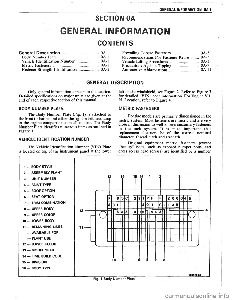
The Body Number Plate (Fig. 1) is attached to
Pontiac models are primarily dimensioned in the
the front tie bar behind either the right or left
headlamp metric system, Most fasteners are metric and are very in the engine On The close in dimension to well-known customary fasteners Number Plate identifies numerous items as outlined in in the inch system. It is most important that Figure 1. re~lacement fasteners be of the correct nominal
VEHICLE IDENTIFICATION NUMBER d&meter, thread pitch and strength.
Original equipment metric fasteners (except
The Vehicle Identification Number (VIN) Plate "beauty" bolts, such
as exposed bumper bolts, and
is located on top of the instrument panel at the lower cross
recess head screws) are identified by a number
1 -- BODY STYLE
2 ASSEMBLY PUNT
3 -- UNIT NUMBER
4 -- PAINT TYPE
5 - ROOF OPTION
6 -- SEAT OPTION
7 - TRIM COMBINATION
8 - UPPER BODY
9 - UPPER COLOR
10 -- LOWER BODY
11 - REMAINING LINES
- AVAILABLE FOR
--PLANT
USE
12 - LOWER COLOR
13 - MODEL YEAR
14 -- TIME BUILD CODE
15 - DIVISION
16 - BODY TvPE
6200224A
Fig. 1 Body Number Plate
Page 5 of 1825
OA-2 GENERAL INFORMATION
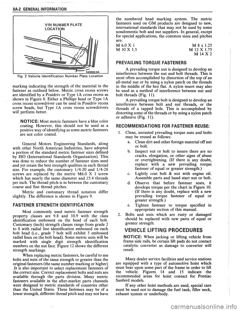
VIN NUMBER PLATE
LOCATION
Fig. 2 Vehicle Identification Number Plate Location
marking indicating the strength of the material in the
fastener as outlined below. Metric cross recess screws
are identified by a Posidriv or Type
1A cross recess as
shown in Figure 8. Either a Phillips head or Type
1A
cross recess screwdriver can be used in Posidriv recess
screw heads, but Type
1A cross recess screwdrivers
will perform better.
NOTICE: Most metric fasteners have a blue color
coating. However, this should not be used as a
positive way of identifying as some metric fasteners
are not color coated.
General Motors Engineering Standards, along
with other North American Industries, have adopted
a portion of the standard metric fastener sizes defined
by
IS0 (International Standards Organization). This
was done to reduce the number of fastener sizes used
and yet retain the best strength qualities in each thread
size. For example, the customary 1/4-20 and 1/4-28
screws are replaced by the metric
M6.0 X 1 screw
which has nearly the same diameter and
25.4 threads
per inch. The thread pitch is in between the customary
coarse and fine thread pitches.
Metric and customary thread notation differ
slightly. The difference is shown in Figure 9.
FASTENER STRENGTH ODENTIFIGATION
Most commonly used metric fastener strength
property classes are 9.8 and 10.9 with the class
identification embossed on the head of each bolt.
Customary (inch) strength classes range from grade 2
to 8 with radial line identification embossed on each
bolt head
(i.e., grade 7 bolt will exhibit 5 embossed
radial lines on the bolt head). Some metric nuts will be
marked with single digit strength identification
numbers on the nut face. Figure 12 shows the different
strength markings.
When replacing metric fasteners, be careful to use
bolts and nuts of the same strength or greater than the
original fasteners (the same number marking or higher)
.It is also important to select replacement fasteners of
the correct size. Correct replacement bolts and nuts are
available through the parts division. Many metric
fasteners available in the after-market parts channels
were designed to metric standards of countries other
than the United States. These fasteners may be of a
lower strength, different thread pitch and may not have the
numbered head marking system. The metric
fasteners used on GM products are designed to new,
international standards that may not be used by some
nondomestic bolt and nut suppliers. In general, except
for special applications, the common sizes and pitches
are:
M 6.0
X 1
M 8 x 1.25
M 10 X 1.5 M 12 X 1.75
M 14x2 I
PREVAILING TORQUE FASTENERS
A prevailing torque nut is designed to develop an
interference between the nut and bolt threads. This is
most often accomplished by distortion of the top of an
all-metal nut or by using a nylon patch on the threads
in the middle of the hex flat.
A nylon insert may also
be used as a method of interference between nut and
bolt threads (Fig. 11).
A prevailing torque bolt is designed to develop an
interference between bolt and nut threads, or the
threads of a tapped hole. This is accomplished by
distorting some of the threads or by using a nylon patch
or adhesive (Fig. 11).
RECOMMENDATIONS FOR FASTENER REUSE: I
Clean, unrusted prevailing torque nuts and bolts
may be reused as follows:
a. Clean dirt and other foreign material off nut
or bolt.
b. Inspect nut or bolt to insure there are no
cracks, elongation, or other signs of abuse
or overtightening. (If there is any doubt,
replace with a new prevailing torque
fastener of equal or greater strength.)
c. Lightly coat bolt
& nut with engine oil.
Assemble parts and hand start nut or bolt.
d. Observe that before fastener seats, it
develops torque per the chart in Figure
10.
(If there is any doubt, replace with a new
prevailing torque fastener of equal or
greater strength.)
e. Tighten fastener to torque specified in
appropriate section of this manual.
Bolts and nuts which are rusty or damaged
should be replaced with new parts of equal or
greater strength.
VEHICLE LIF"TING PROCEDURES
NOTICE: When jacking or lifting vehicle from
frame side rails, be certain lift pads do not contact
catalytic converter as damage to converter will
result.
Many dealer service facilities and service stations
are equipped with a type of automotive hoist which
must bear upon some part of the frame in order to lift
the vehicle. Figures 14 and 15 indicate the
recommended areas for hoist contact for Pontiac
Sunbird models.
If any other hoist methods are used, special care
must be used not to damage the fuel tank, filler neck,
I
exhaust system or underbody. I
Page 12 of 1825
GENERAL INFORMATION OA-9
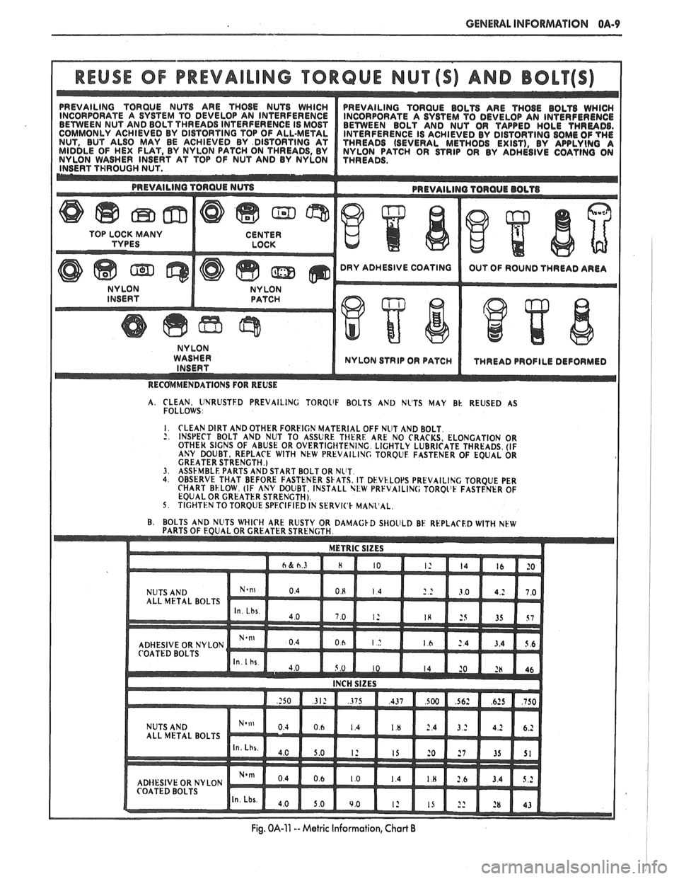
REUSE OF PREVAILING "TRQUE NUT AND BOLT
WASHER NYLON STRIP OR PATC
I
A. CLEAN, llNRUSTFD PREVAILING TORQllF BOLTS AND NL'TS MAY Bk. REUSED AS FOLL.0WS I I. CLEAN DIRT AND OTHER FORFICN MATERIAL OFF NUT AND BOLT. 2, INSPECT BOLT
AND NUT TO ASSURE THERE ARE NO CRACKS. ELONGATION OR OTHER SIGNS OF ABUSE OR OVERTIGIiTENING. LIGHTLY LUBRICATE THREADS. (IF
ANY DOUBT, REPLACE WITH NEW PREVAILING TOROLE FASTENER OF EQUAL OR
GREATER STRENGTH.)
3. ASSFMBLE PARTS AND START BOLT OR NLIT. 4. OBSERVE THAT BEFORE FASTENER SkATS. IT DEVk.LOPS PREVAILING TORQUE PER
CHART BELOW. (IF ANY DOUBT, INSTALL NliW PRFVAILIN(; TORQL'F FASTENER OF
EQUAL OR GREATER STRENGTH).
5. TIGHTEN TO TORQUE SPECIFIED IN SERVl('k MANl'AL,
Page 14 of 1825
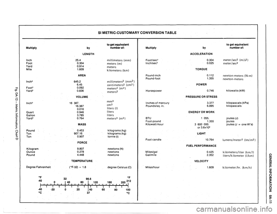
SI METRIC-CUSTOMARY CONVERSION TABLE
to get equivalent
by nurnber of: Multiply
to get equivalent
by number ol: Multiply
LENGTH ACCELERATION
Inch Foot
Yard
Mile millimeters (mm)
meters (m) meters
kilometers (km) TORQUE
AREA
newton-meters (N-m) newton-meters
millimeters2 (mm2) centimeters2 (cm2 ) meters' (m2) meters2
POWER
Horsepower
VOLUME PRESSURE
OR STRESS
3.377 6.895
mm3 cm3
liters (I)
liters
liters
meters3
(ma)
Inches of mercury
Poundslsq. in. kilopascals (kPa) kilopascals
Quart
Gallon
Yard3
ENERGY OR WORK
BTU
Foot-pound
Kilowatt-hour joules
(J)
joules
joules (J
= one W's) MASS
Pound
Ton Ton kilograms
(kg)
kilograms (kg)
tonne (t)
Foot candle
FORCE
FUEL PERFORMANCE
Kilogram
Ounce Pound newtons (N) newtons
newtons Mileslgal Gallmile kilometerslliter (km/l) literslkilometer (Ilkm)
TEMPERATURE
VELOCITY
1.609 Degree Fahrenheit
degree Celsius (C) Mileslhour
Page 16 of 1825
- -
GENERAL INFORMATION OA-13
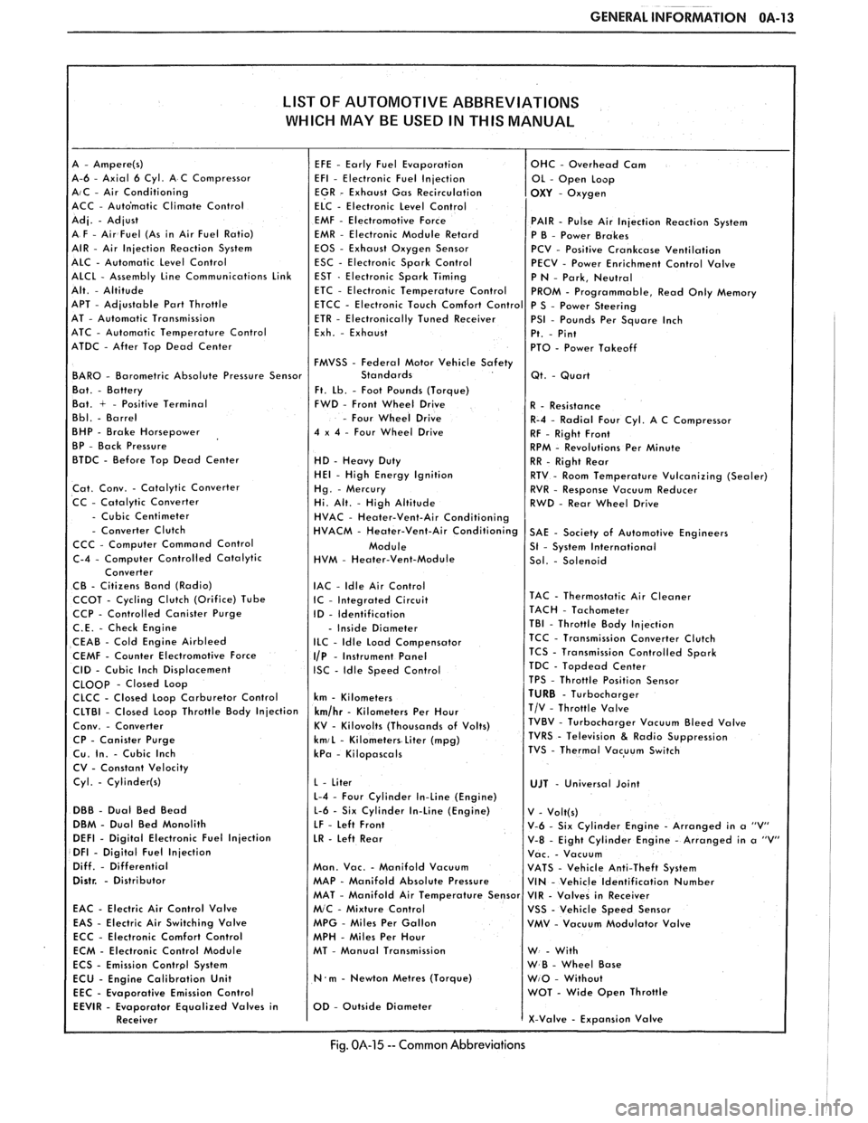
LIST OF AUTOMOTIVE ABBREVIATIONS
WHICH MAY
BE USED IN THIS MANUAL
A-6 - Axial 6 Cyl. A C Compressor AIC - Air Conditioning
ACC - Auto'matic Climate Control
EMF
- Electromotive Force PAIR - Pulse Air Injection Reaction System
EMR - Electronic Module Retard
P B - Power Brakes
EOS - Exhaust Oxygen Sensor
PCV - Positive Crankcase Ventilation
ESC - Electronic Spark Control
PECV - Power Enrichment Control Valve
APT
- Adjustable Part Throttle
AT - Automatic Transmission
ATC - Automatic Temperature Control
ATDC
- After Top Dead Center
FMVSS
- Federal Motor Vehicle Safety BAR0 - Barometric Absolute Pressure Sensor
Ft. Lb. - Foot Pounds (Torque)
Bat. + - Positive Terminal FWD - Front Wheel Drive
- Four Wheel Drive
BHP - Brake Horsepower 4 x 4 - Four Wheel Drive
BP - Back Pressure
BTDC - Before Top Dead Center
HD - Heavy Duty HE1 - High Energy Ignition
Cat. Conv. - Catalytic Converter
CC - Catalytic Converter
- Cubic Centimeter - Converter Clutch
CCC - Computer Command Control
HVM
- Heater-Vent-Module
IAC
- ldle Air Control CCOT - Cycling Clutch (Orifice) Tube IC - Integrated Circuit CCP - Controlled Canister Purge
ID - Identification
C.E. - Check Engine - Inside Diameter
CEAB - Cold Engine Airbleed ILC - Idle Load Compensator
CEMF - Counter Electromotive Force I/P - Instrument Panel
CID - Cubic Inch Displacement ISC - Idle Speed Control CLOOp - Closed Loop
CLCC - Closed Loop Carburetor Control km - Kilometers
CP
- Canister Purge kmiL - Kilometers Liter (mpg) Cu. In. - Cubic Inch kPa - Kilopascals
CV - Constant Velocity
Cyl.
- Cylinder(s)
L-4 - Four Cylinder In-Line (Engine)
DBB - Dual Bed Bead L-6 - Six Cylinder In-Line (Engine)
DBM - Dual Bed Monolith
LF - Left Front DEFl - Digital Electronic Fuel Injection LR - Left Rear DFI - Digital Fuel Injection
Diff. - Differential Man. Vac. - Manifold Vacuum Distr. - Distributor MAP - Manifold Absolute Pressure
EAC
- Electric Air Control Valve
EAS - Electric Air Switching Valve MPG - Miles Per Gallon
ECC - Electronic Comfort Control
MPH - Miles Per Hour
ECM - Electronic Control Module MT - Manual Transmission
N.m - Newton Metres (Torque)
Emission Control
Fig. 014-15 -- Common Abbreviations
Page 18 of 1825
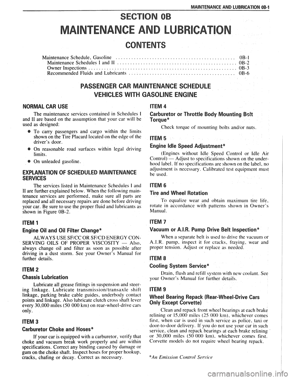
MAINTENANCE AND LUBRICATION OB-1
SECTION OB
NTENANCE AND LUBR
CONTENTS
Maintenance Schedule, Gasoline .............................................. OB-l
Maintenance Schedules I and 11 .............................................. OB-2
Owner Inspections
......................................................... OB-3
Recommended Fluids and Lubricants ......................................... OB-6
PASSENGER CAR MAINTENANCE SCHEDULE
VEHICLES
WITH GASOLINE ENGINE
NORMAL CAR USE ITEM 4
The maintenance services contained in Schedules I Carburetor or Throttle Body Mounting Bolt
and 11 are based on the assumption that your car will be Torque* used as designed:
Check torque of mounting bolts and/or nuts. @ To carry passengers and cargo within the limits
shown on the Tire Placard located on the edge of the ITEM 5 driver's door.
@ On reasonable road surfaces within legal driving Engine Idle Speed Adjustment*
limits. (Engines
without Idle Speed Control or Idle Air
Control) - Adjust to specifications shown on the under- @ On unleaded gasoline.
hood label. If no specifications are shown on the label, no
adjustment is necessary. Calibrated test equipment must
EXPLANATION OF SCHEDULED MAINTENANCE be used. SERVICES
The services listed in Maintenance Scheduies I and ITEM 6
11 are further explained below. When the following main- ~i~~ and wheel aotation tenance services are performed, make sure all parts are
replaced and all necessary repairs are done before driving To equalize wear and obtain maximum tire life,
your car. Be sure to use the proper fluid and lubricants as rotate in accordance with patterns shown in Owner's
shown in Figure OB-2. Manual.
ITEM 1
Engine Oil and Oil Filter Change*
ALWAYS USE SFICC OR SF/CD ENERGY CON-
SERVING OILS OF PROPER VISCOSITY
- Also.
always change oil and filter as soon as possible after
driving in a dust storm. See your Owner's Manual for
further details.
ITEM 2
Chassis Lubrication
Lubricate all grease fittings in suspension and steer-
ing linkage. Lubricate
transmissionltransaxle shift
linkage, parking brake cable guides, underbody contact
points and linkage. Also lubricate clutch cross shaft lever
every
30,000 miles (50 000 km) on rear-wheel-drive cars
only.
ITEM 3
Carburetor Choke and Hoses*
If your car is equipped with a carburetor, verify that
choke and vacuum break work properly and are within
specifications. Correct any binding caused by damage or
gum on the choke shaft. Inspect hoses for proper hookup,
cracks, chafing or decay. Correct as necessary.
Vacuum or A.I.R. Pump Drive Belt Inspection*
When a separate belt is used to drive the vacuum or
A.I.R.
pump, inspect it for cracks, fraying, wear and
proper tension. Adjust or replace as needed.
ITEM 8
Cooling System Service*
Drain, flush and refill system with new coolant. See
your Owner's Manual
for further details.
ITEM 9
Wheel Bearing Repack (Rear-Wheel-Drive Cars
Only Except Corvette)
Clean and repack front wheel bearings at each brake
relining or 15,000 miles
(25 000 km), whichever comes
first, when car is used in such service as police, taxi or
door-to-door delivery. If you do not use your car in such
service, clean and repack bearings at each brake relining
or 30,000 miles
(50 000 km), whichever comes first.
Corvette models do not require wheel bearing repack.
Page 47 of 1825
18-4 AIR CONDITIONING
If replacement of the pressure cycling switch is
necessary, it is important to note that this may be done
without removing the refrigerant charge.
A Schrader-
type valve is located in the pressure switch fitting.
During replacement of the pressure switch, a new
oiled O-ring must be installed and the switch assem-
bled to the specified torque of
6- 13 N*m (5- 10 lb. ft.).
Power Steering Gut-OH, or Anticipate
Switch
Engine idle quality on some cars is maintained
by cutting off the compressor (switch normally
closed) when high power steering loads are imposed.
On other cars the switch (normally open) provides a
signal to the ECM to allow engine control systems to
compensate for high-power steering loads.
Wide-Open Tkroale (WOT) Compressor
Cut-Out
Switch
A switch located on the throttle corltrols of some
carburetor equipped cars opens the circuit to the com-
pressor clutch during full throttle acceleration. The
switch activates a relay that controls the compressor
clutch. During full throttle acceleration
on cars
equipped with TBI or
Em, the TPS sends a signal to
the ECM, thereby controlling the compressor clutch.
Air Conditioning Time Delay Relay
This relay on some cars controls the current to
the entire air conditioning system and provides a short
delay of air conditioning operation upon start-up.
Constant Run Relay
Engine idle quality on some cars is maintained
by a "constant run" system (constant run relay) that
eliminates compressor cycling during engine idle for a
predetermined time after the vehicle has come to rest
from road speed.
If the idle period continues for an
extended time, the
A/C system may return to a con-
ventional C.C.O.T. mode for a short time to prevent
system freeze-up. The
A/C control relay and constant
run relays are both controlled by the Electronic Con-
trol Module (ECM) which determines operating con-
ditions by evaluating input from the distributor
(engine speed), vehicle speed sensor, air sensor and
A/C compressor "on" signal.
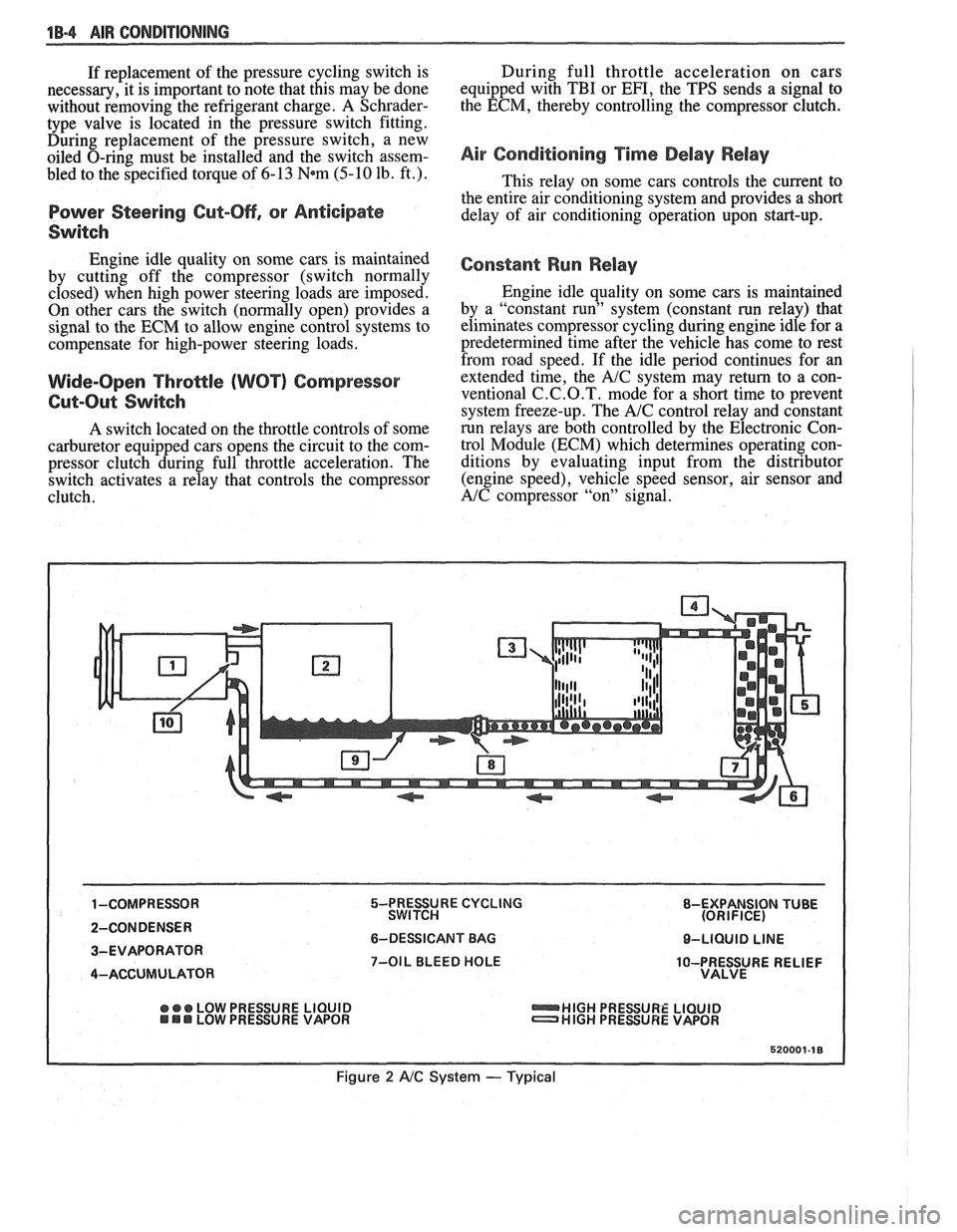
5-PRESSURE CYCLING 8-EXPANSION TUBE
SWITCH (ORIFICE)
6-DESSICANT BAG O-LIQUID LINE
7-OIL BLEED HOLE
10-PRESSURE RELIEF
VALVE
@ ee LOW PRESSURE LIQUID HIGH PRESSURE LIQUID LOW PRESURE VAPOR HIGH PRESSURE VAPOR
Figure 2 A/C System - Typical
Page 55 of 1825
18-12 AIR CONDITIONING
ELEGTRICAWACUUM SYSTEM
DIAGNOSIS
When diagnosing problems in the electrical sys-
tems of the air conditioning system, consult section
8A.
LEAK TESTING THE REFRIGERANT
SYSTEM
Whenever a refrigerant leak is suspected in the
system or a service operation performed which results
in disturbing lines or connections, it is advisable to
test for leaks.
Liquid Leak Detectors
There are a number of locations (fittings,
valves, etc.) on the air conditioning system where a
liquid leak detector solution may be used to pinpoint
refrigerant leaks.
By applying test solution to the area in question
with the swab that is attached to the bottle cap, bub-
bles will form within seconds if there is a leak.
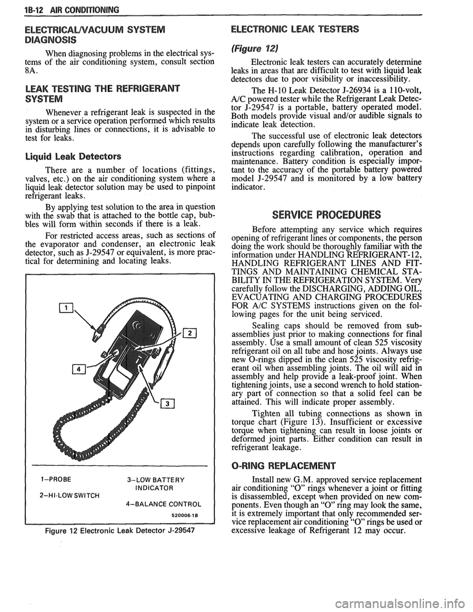
For restricted access areas, such as sections of
the evaporator and condenser, an electronic leak
detector, such as
5-29547 or equivalent, is more prac-
tical for determining and locating leaks.
3-LOW BATTERY
INDICATOR
2-HI-LOW SWITCH
4-BALANCE CONTROL
Figure 12 Electronic Leak Detector J-29547
ELECTRONIC LEAK TESTERS
(Figure 12)
Electronic leak testers can accurately determine
leaks in areas that are difficult to test with liquid leak
detectors due to poor visibility or inaccessibility.
The H-10 Leak Detector 5-26934 is a 110-volt,
A/C powered tester while the Refrigerant Leak Detec-
tor J-29547 is a portable, battery operated model.
Both models provide visual
and/or audible signals to
indicate leak detection.
The successful use of electronic leak detectors
depends upon carefully following the manufacturer's
instructions regarding calibration, operation and
maintenance. Battery condition is especially impor-
tant to the accuracy of the portable battery powered
model
5-29547 and is monitored by a low battery
indicator.
SERVICE PROCEDURES
Before attempting any service which requires
opening of refrigerant lines or components, the person
doing the work should be thoroughly familiar with the
information under HANDLING REFRIGERANT- 12,
HANDLING REFRIGERANT LINES AND FIT-
TINGS AND MAINTAINING CHEMICAL STA-
BILITY IN THE REFRIGERATION SYSTEM. Very
carefully follow the DISCHARGING, ADDING OIL,
EVACUATING AND CHARGING PROCEDURES
FOR
A/C SYSTEMS instructions given on the fol-
lowing pages for the unit being serviced.
Sealing caps should be removed from sub-
assemblies just prior to making connections for final
assembly. Use a small amount of clean 525 viscosity
refrigerant oil on all tube and hose joints. Always use
new O-rings dipped in the clean 525 viscosity refrig-
erant oil when assembling joints. The oil will aid in
assembly and help provide a leak-proof joint. When
tightening joints, use a second wrench to hold station-
ary part of connection so that
a solid feel can be
attained. This will indicate proper assembly.
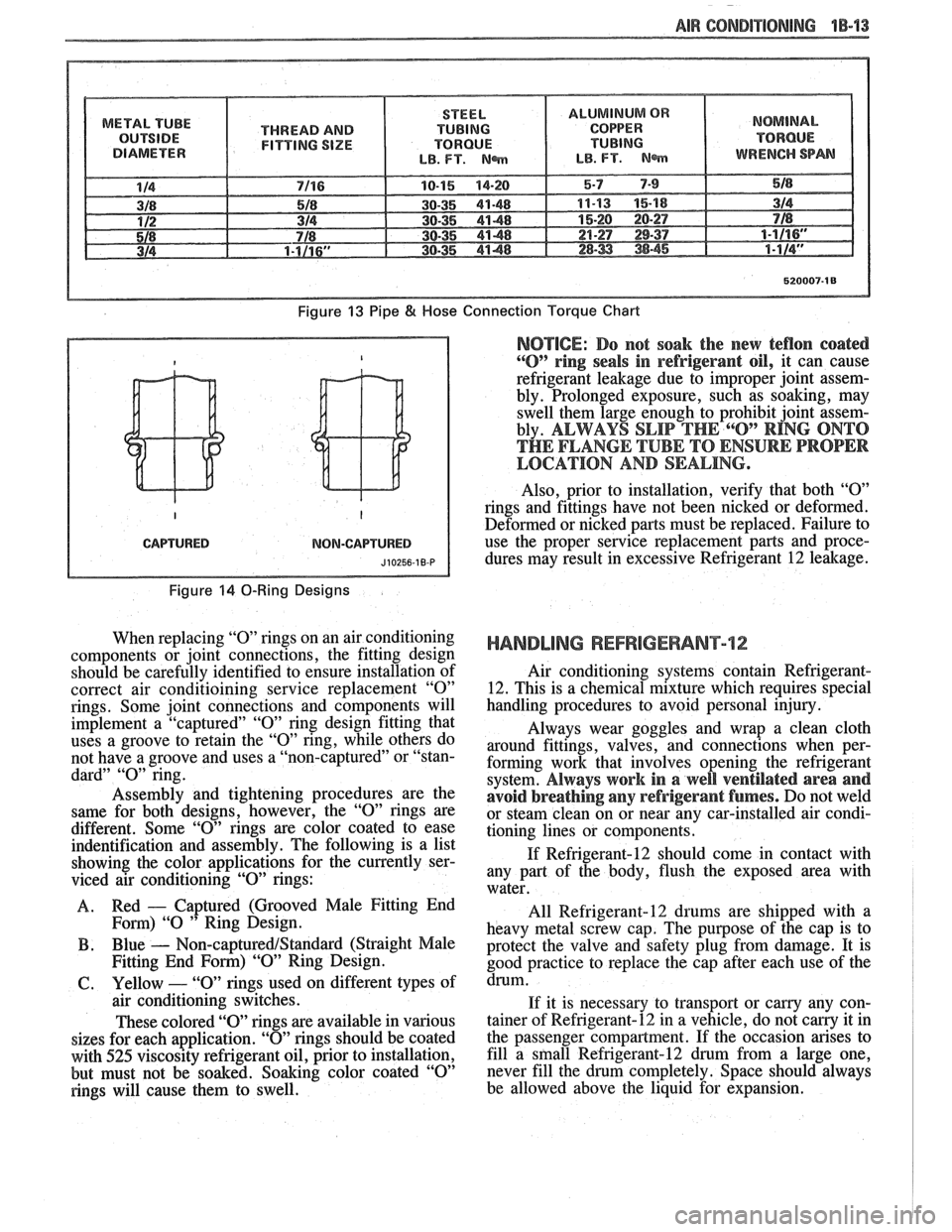
Tighten all tubing connections as shown in
torque chart (Figure
13). Insufficient or excessive
torque when tightening can result in loose joints or
deformed joint parts. Either condition can result in
refrigerant leakage.
O-RING REPWCEMENT
Install new G. M. approved service replacement
air conditioning
"0" rings whenever a joint or fitting
is disassembled, except when provided on new com-
ponents. Even though an
"0" ring may look the same,
it is extremely important that only recommended ser-
vice replacement air conditioning
"0" rings be used or
excessive leakage of Refrigerant 12 may occur.
Page 56 of 1825
-
AIR CONDlTlQNlNG 1B-'13
METAL TUBE
THREAD AND
FITTING SIZE
Figure 13 Pipe 8( Hose
CAPTURED NOM-CAPTURED
Figure 14 0-Ring Designs
When replacing "0" rings on an air conditioning
components or joint connections, the fitting design
should be carefully identified to ensure installation of
correct air conditioining service replacement
"0"
rings. Some joint connections and components will
implement a "captured"
"0" ring design fitting that
uses a groove to retain the
"0" ring, while others do
not have a groove and uses a "non-captured" or "stan-
dard"
"0" ring.
Assembly and tightening procedures are the
same for both designs, however, the
"0" rings are
different. Some
"0" rings are color coated to ease
indentification and assembly. The following is a list
showing the color applications for the currently ser-
viced air conditioning
"0" rings:
A. Red
- Captured
(Grooved Male Fitting End
Fom) "0 " Ring Design.
B . Blue - Non-captured/Standard (Straight Male
Fitting End
Form) "09' Ring Design.
61. Yellow - "0" rings used on different types of
air conditioning switches.
These colored "O" rings are available in various
sizes for each application.
"0" rings should be coated
with
525 viscosity refrigerant oil, prior to installation,
but must not be soaked. Soaking color coated
"0"
rings will cause them to swell.
Connection Torque Chart
NOTICE: Do not soak the new teflon coated
"0" ring seals in refrigerant oil, it can cause
refrigerant leakage due to improper joint assem-
bly. Prolonged exposure, such as soaking, may
swell them large enough to prohibit joint assem-
bly.
ALWAYS SLIP THE 6"O" RING ONTO
THE FLANGE TUBE TO ENSURE PROPER
LOCATION AND SEALING.
Also, prior to installation, verify that both "09'
rings and fittings have not been nicked or deformed.
Deformed or nicked
parts must be replaced. Failure to
use the proper service replacement parts and proce- dures may result in excessive Refrigerant
12 leakage.
HANDLING REFRIGERANT12
Air conditioning systems contain Refrigerant-
12. This is a chemical mixture which requires special
handling procedures to avoid personal injury.
Always wear goggles and wrap a clean cloth
around fittings, valves, and connections when per-
forming work that involves opening the refrigerant
system.
Always work in a well ventilated area and
avoid breathing
any refrigerant fumes. Do not weld
or steam clean on or near any car-installed air condi-
tioning lines or components.
If Refrigerant-12 should come in contact with
any part of the body, flush the exposed area with
water.
All
Refrigerant-12 drums are shipped with a
heavy metal screw cap. The purpose of the cap is to
protect the valve and safety plug from damage. It is
good practice to replace the cap after each use of the
drum.
If it is necessary to transport or carny any con-
tainer of Refrigerant-12 in a vehicle, do not
carry it in
the passenger compartment. If the occasion arises to
fill a
sfnall Refrigerant-12 drum from a large one,
never fill the drum completely. Space should always
be allowed above the liquid for expansion.