oil capacity PONTIAC FIERO 1988 Service Repair Manual
[x] Cancel search | Manufacturer: PONTIAC, Model Year: 1988, Model line: FIERO, Model: PONTIAC FIERO 1988Pages: 1825, PDF Size: 99.44 MB
Page 10 of 1825
GENERAL INFORMATION OA-7
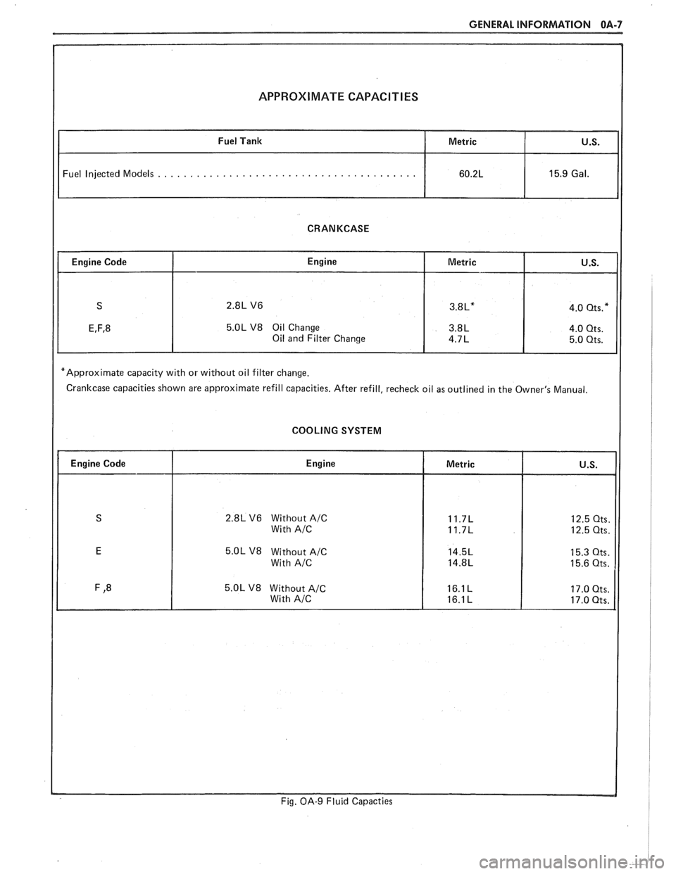
APPROXIMATE CAPACITIES
Fuel Injected Models . . . . . . . . . . . . . . . . . . . . . . . . . . . . . . . . . . . . . . . .
CRANKCASE
5.OL V8 Oil Change
*Approximate capacity with or without oil filter change.
Crankcase capacities shown are approximate refill capacities. After refill, recheck oil as outlined in the Owner's Manual.
COOLING SYSTEM
2.8L V6 Without A/C
5.OL V8 Without A/C
Fig. OA-9 Fluid Capacties
Page 57 of 1825
18-14 AIR CONDITIONING
HANDLING OF REFRIGERANT LINES AND
FI-INGS
Tighten all tubing connections as shown in
torque chart (Figure 13). INSUFFICIENT OR
EXCESSIVE TORQUE WHEN TIGHTENING CAN
RESULT IN LOOSE JOINTS OR DEFORMED
JOINT PARTS. Either condition can result in refrig-
erant leakage.
All metal tubing lines should be free of dents or
kinks to prevent loss of system capacity due to line
restriction.
@ The flexible hose lines should never be bent to a
radius of less than four (4) times the diameter of
the hose.
@ The flexible hose lines should never be allowed
to come within a distance of
63.5mm (2-112") of
the exhaust manifold.
@ Flexible hose lines should be inspected regularly
for leaks or brittleness and replaced with new
lines if deterioration or leaking is found.
@ When disconnecting any fitting in the refrigera-
tion system, the system must first be discharged
of all Refrigerant- 12. Proceed very cautiously
regardless of gauge readings. Open very slowly,
keeping face and hands away so that no injury
can occur if there happens to be liquid
Refriger-
ant-12 in the line. If pressure is noticed when
fitting is loosened, allow it to bleed off as
described under DISCHARGING, ADDING
OIL, EVACUATING AND CHARGING PRO-
CEDURES FOR
A/C SYSTEMS.
@ In the event any refrigerant line is opened to the
atmosphere, it should be immediately capped or
taped to prevent entrance of moisture and dirt,
which can cause internal compressor wear or
plugged lines, in the condenser and evaporator
core and expansion (orifice) tubes or compressor
inlet screens.
@ The use of the proper wrenches when making
connections on O-ring fittings is important. The
opposing fitting should always be backed up
with a wrench to prevent distortion of connecting
lines or components. When connecting the flexi-
ble hose connections, it is important that the
swaged fitting and the flare nut, as well as the
coupling to which it is attached, be held at the
same time using three
(3) different wrenches to
prevent turning the fitting and damaging the
ground seat.
@ O-rings and seats must be in perfect condition. A
burr or piece of dirt may cause a refrigerant leak.
When replacing the O-ring, first dip it in clean
525 viscosity refrigeration oil.
MAINTAINING CHEMICAL STABILITY IN
THE
REFRIGERATION SYSTEM
The efficient operation and life of the air condi-
tioning system is dependent upon the chemical stabil-
ity of the refrigeration system. When foreign materials, such as
dirt, air, or moisture, contaminate
the refrigeration system, they will change the stability
of the Refrigerant-12 and 525 viscosity compressor
oil. They will also affect pressure-temperature rela-
tionship, reduce efficient operation and possibly cause
interior corrosion and abnormal wear of moving parts.
The following general practices should be
observed to insure chemical stability in the system:
1. Before disconnecting a refrigerant connection,
wipe away any dirt or oil at and near the connec-
tion to reduce the possibility of dirt entering the
system. Both sides of the connection should be
capped, plugged or taped as soon as possible to
prevent the entry of dirt, foreign material and
moisture.
2. Keep tools clean and dry. This includes the
manifold gauge set and replacement parts.
3. When adding 525 viscosity refrigerant oil (see
ADDING OIL in the DISCHARGING,
ADDING OIL, EVACUATING AND
CHARGING PROCEDURES FOR
AIC SYS-
TEMS, the transfer device and container should
be clean and dry to assure that refrigeration oil
remains as moisture-free as possible.
4. When it is necessary to "open" an
AIC system,
have everything needed ready and handy so that
as little time as possible will be required to per-
form the operation. Do not leave the
AIC system
open any longer than is necessary.
5. Any time the
A/C system has been "opened," it
should be properly evacuated before recharging
with Refrigerant- 12 according to the DIS-
CHARGING, ADDING OIL, EVACUATING
& CHARGING PROCEDURES FOR AIC
SYSTEMS.
All service parts are dehydrated and sealed
prior to shipping. They should remain sealed until just
prior to making connections. All parts should be at
room temperature before uncapping. (This prevents
condensation of moisture from the air entering the
system.) If, for any reason, caps are removed but the
connections are not made, parts should be resealed as
soon as possible.
DISCHARGING, ADDING OIL,
EVACUATING AND CHARGING
PROCEDURES FOR NC SYSTEMS
The refrigerant system may be discharged,
evacuated and charged using air conditioning service
charging station J-23500-01 or equivalent, or the
manifold and gauge set
5-23575-01 and 420ml (14
oz.) disposable cans of Refrigerant-12 (Figure 16).
Charging lines from the charging station or
manifold and gauge set require the use of gauge
adapters to connect to the system service fitting.
A
straight gauge adapter 5-5420 and a 90" angle gauge
adapter
5-9459 are available (see A/C Special Tools).
Always wear goggles and wrap a clean cloth
around fittings and connections when doing work that
Page 418 of 1825
ENGINE COOLING BB-7
NOTICE: If recommended quality antifreeze is
used, supplemental inhibitors or additives claiming
to provide increased cooling capability are not
necessary. They may be detrimental to the efficient
operation of the system, and represent an
unnecessary operating expense.
Every 12 months or 15,000 miles, the cooling
system should be serviced as follows;
1. Wash radiator cap and filler neck with clean
water.
2. Check coolant for proper level and freeze
protection.
3. Pressure test system and radiator cap for proper
pressure holding capacity, 103
kPa (15 psi). If
replacement of cap is required, use the proper cap
specified for car model.
4. Tighten hose clamps and inspect all hoses. Replace
hoses whenever cracked, swollen or otherwise
deteriorated.
5. Clean frontal area of radiator core and air
conditioning condenser.
DRAINING AND REFILLING THE COOLING
SYSTEM
Replace hoses every 24 months or 30,000 miles or
earlier if cracked, swollen or otherwise deteriorated.
Every two years or 30,000 miles, whichever first
occurs, the cooling system should be flushed and
refilled using the following recommended procedure:
1. Remove radiator cap, or thermostat housing cap
(VIN
0, J, R and U), when engine is cool by:
a. Slowly
rotating cap counterclockwise to
detent. (Do not press down while rotating.)
b. Wait until any
residual pressure (indicated
by a hissing sound) is relieved.
c. After all hissing ceases, press down on cap
while continuing to rotate
counterclockwise.
CAUTION: To avoid the danger of
being burned, do not remove radiator
cap while engine and radiator are still
hot. Scalding fluid and steam may be
blown out under pressure.
2. Remove the thermostat by using the wire handle
to lift it out of the housing (VIN
0, J, R and U).
3. With the thermostat removed, reinstall the
thermostat housing cap (VIN
0, J, R and U).
4. Open radiator drain valve and block drain plugs
to drain coolant. On VIN R and
9 (P series)
engines, open coolant pipe plugs.
5. Close valve. Reinstall drain plugs, and add
sufficient water to fill system.
6. Run engine, drain and refill the system, as
described in steps
4 and 5 a sufficient number of
times, until the drained liquid is nearly colorless.
Important
BLOCK DRIVE WHEELS, place
transmission in PARK (automatic
transmission) or NEUTRAL (manual
transmission) and set the parking brake. 7.
Allow system to drain completely. Then close
radiator drain valve tightly, and reinstall block
drain plugs.
8. Remove recovery cap leaving hoses in place.
Remove coolant recovery tank and empty of
fluid. Flush tank with clean water, drain and
reinstall.
9. Add sufficient ethylene glycol coolant, meeting
GM specification 1825-M, to provide the
required freezing and corrosion protection
- at
least 50 percent solution -37°C (-34°F). Fill
radiator to the base of the radiator fill neck and
add sufficient coolant to the recovery tank to
raise level to the "FULL" mark. Reinstall
recovery tank cap.
10. Run engine, with radiator cap or thermostat
housing cap removed, until normal operating
temperature is reached. (Radiator upper hose
becomes hot.)
11. With engine idling, add coolant until level
reaches bottom of filler neck and reinstall cap,
making certain arrows line up with overflow tube.
CAUTION: Under some conditions, the
ethylene glycol in engine coolant is
flammable. To help avoid being
burned when adding coolant, DO NOT
spill
it on the exhaust system or hat
engine parts.
It is the owner's responsibility to keep the freeze
protection at a level appropriate to the
temperatures which may occur in the area of
vehicle operation.
a. Maintain
cooling system freeze protection
at
-37°C (-34"F), to ensure protection
against corrosion and loss of coolant from
boiling, even though freezing temperatures
are not expected.
b. Add ethylene glycol base coolant that meets
GM Specification 1825-M, when coolant
additions are required because of coolant
loss, or to provide additional protection
against
freezing at temperatures lower than
-37°C (-34°F).
NOTICE: Alcohol or methanol base coolants, or
plain water, are not recommended at any time.
DRlVE BELT
NOTICE: Routine inspection of the belt may
reveal cracks in the belt ribs. These cracks will
not impair belt performance and therefore should
not be considered a problem requiring belt
replacement. However, the belt should be
replaced if belt slip occurs or if sections of the
belt ribs are missing.
A single (serpentine) belt is used to drive all
engine accessories formerly driven by multiple drive
belts. All belt driven accessories are ridgedly mounted
with belt tension maintained by a spring loaded
tensioner.
The drive belt tensioner has the ability to control
belt tension over a fairly broad range of belt lengths.
Page 637 of 1825
6E2-C"1-2 DRIVEABILITY AND EMISSIONS - 5.OL (VIN E)
With this system, any blow-by in excess of the
system capacity (from a badly-worn engine, sustained
heavy load,
etc.) is exhausted into the air cleaner and
is drawn into the engine.
Proper operation of the PCV System is dependent
upon a sealed engine. If oil sludging or dilution is
noted, and the PCV System is functioning properly,
check engine for possible cause and correct to ensure
that system will function as intended.
Results of Incorrect PCV Operation
@ A plugged valve or hose may cause:
@ Rough idle.
@ Stalling or slow idle speed.
Oil leaks.
@ Oil in air clcaner.
@ Sludge in engine.
ON-CAR SERVICE
An engine which is operated without any
crankcase ventilation can be damaged. Therefore, it is
important to replace the
PCV valve and air cleaner
breather at intervals shown in Section
"OB".
Periodically, inspect the hoses and clamps and
replace any showing signs of deterioration.
PARTS INFORMATION
PART NAME GROUP
Air Cleaner ......................... 3.402
................ Valve Asm, UCase Vent 1.745
Page 802 of 1825
DRIVEABILITY AND EMISSIONS 2.8L (VIN S) 6E3-C13-1
SECTION C13
POSITIVE CRANKCASE VENTILATION (PC\/)
.... GENERAL DESCRIPTION ................ C13-1 FUNCTIONAL CHECK OF PCV VALVE C13-1
RESULTS OF INCORRECT OPERATION .... C13-1 ON-CAR SERVICE ..................... C13-2
DIAGNOSIS
......................... C13-1 PARTS INFORMATION ................. C13-2
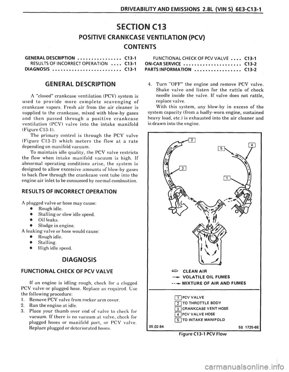
GENERAL DESCRIPTION 4. Turn "OFF" the engine and remove PCV valve.
Shake valve and listen for the rattle of check
A "closed" crankcase ventilation (PCV) system is needle inside
the valve. If valve does not rattle,
used to provide more complete scavenging of replace
v4 ~1 1 ve.
crankcase vapors. Fresh air from the air cleaner is With this
system, any blow-by in excess of the
slipplied to the crankcase, mixed with blow-by gases system capacity (from a badly-worn engine, sustained
and then passed through a positive crankcase heavy load, etc.) is exhausted into the air cleaner and
ventilation
(PCV) valve into the intake manifold isdrawn into theengine.
(Figure C13-1).
The primary control is through the PCV valve
(Figure
(213-2) which meters the flow at a rate
depending on manifold vacuum.
To maintain idle quality, the PCV valve restricts
the flow when intake manifold vacuum is high. If
abnormal operating conditions arise, the system is
designed to allow excessive amounts
of I,low-by gases
to back flow through the crankcase vent tube into the
engine air inlet to be consumed by normal combustion.
RESULTS OF INCORRECT OPERATION
A plugged valve or hose may cause:
@ Rough idle.
@ Stalling or slow idle speed.
@ Oil leaks.
@ Sludge in engine.
A leaking valve or hose would cause:
@ Rough idle.
@ Stalling.
@ Iiigh idle speed.
DIAGNOSIS
FUNCTIONAL CHECK OF PCV VALVE
If an engine is idling rough, check for a clogged
PCV valve or plugged hose. Replace as required. Use
the following procedure:
1. Remove PCV valve from rocker arm cover.
2. Run the engine at idle.
3. Place your thumb over end of vi~lcce to check for
vacuum. If there is
no vacuum at valve, chcck for
plugged hoses or
lrlanifold port, or 1'CV valve.
Replace plugged or dcterioratcd hoses.
a CLEAN AIR
VOLATILE OIL FUMES
---e- MIXTURE OF AIR AND FUMES
PCV VALVE
1 TO THROTTLE BODY
CRANKCASE VENT HOSE
1 PCV VALVE HOSE
150 INTAKE MANIFOLD
Figure C13-1 PCV Flow
Page 956 of 1825
DRIVEABILITY AND EMISSIONS 5.OL (VIN F) & 5.7L (VIN 8) 6E3-C13-1
SECTION C13
POSITIVE CRANKCASE VENTlLATlON (PCV)
CONTENTS
GENERAL DESCRIPTION ................ C13-1 FUNCTIONAL CHECK OF PCV VALVE .... C13-1
RESULTS OF INCORRECT OPERATION .... C13-1 ON-CARSERVICE ..................... C13-2
DIAGNOSIS
......................... C13-1 PARTS INFORMATION ................. C13-2
GENERAL DESCRIPTION
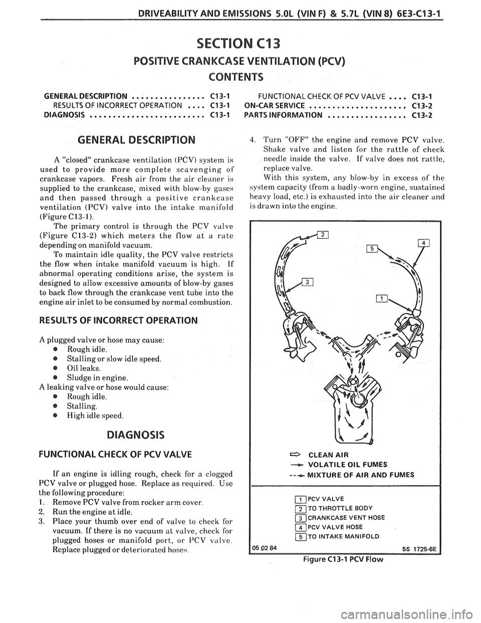
A "closed" crankcase ventilation (PCV) system is
used to provide more
cor~lplete scavenging of
crankcase vapors. Fresh air
from the air cleaner is
supplied to the crankcase, mixed with blow-by gases
and then passed through a positive crankcase
ventilation
(PCV) valve into the intake manifold
(Figure C13-I).
The primary control is through the PCV valve
(Figure
(213-2) which meters the flow at a rate
depending on manifold vacuum.
To maintain idle quality, the PCV valve restricts
the flow when intake manifold vacuum is high. If
abnormal operating conditions arise, the system is
designed to allow excessive amounts of blow-by gases
to back flow through the crankcase vent tube into the
engine air inlet to be consumed by normal combustion.
RESULTS OF INCORRECT OPERATION
A plugged valve or hose may cause:
@ Rough idle.
@ Stalling or slow idle speed.
@ Oil leaks.
@ Sludge in engine.
A leaking valve or hose would cause:
@ Rough idle.
@ Stalling.
@ High idle speed.
FUNCTIONAL CHECK OF PCV VALVE
If an engine is idling rough, check for a clogged
PCV valve or plugged hose. Replace as required. Use
the following procedure:
1. Remove PCV valve from rocker arm cover.
2. Run the engine at idle.
3. Place your thumb over end of valve lo check for
vacuum. If there is no vacuum at valve, check for
plugged hoses or manifold port, or
PCV valve.
Replace plugged or deteriorated hoses.
4. Turn "OFF" the engine and remove PCV valve.
Shake valve and listen for the rattle of check
needle inside the valve. If valve does not rattle,
replace valve.
With this system, any blow-by in excess of the
system capacity (from a badly-worn engine, sustained
heavy load,
etc.) is exhausted into the air cleaner and
is drawn into the engine.
a CLEAN AIR
VOLATILE OIL FUMES
--+- MIXTURE OF AIR AND FUMES
PCV VALVE
120 THROTTLE BODY
13 CRANKCASE VENT HOSE
1 PCV VALVE HOSE
I 150 INTAKE MANIFOLD I
Figure C13-1 PCV Flow
Page 974 of 1825
DRIVEABILIW AND EMISSIONS - FUEL INJECTION 6E-13
When the voltage to the solenoid is turned off, (de-
energized), a spring raises the plunger.
ESC - ELECTRONIC SPARK CONTROL - Used to
sense detonation and retard spark advance when
detonation occurs.
EST - ELECTRONIC SPARK TIMING - ECM
controlled timing of ignition spark.
EVRV - ELECTRONIC VACUUM REGULAWR
VALVE - Controls EGR vacuum.
FED - FEDEWL - VehicleIEngine available in all
states except California.
GROUND - The negative (-) side of the battery.
Also could be a wire (conductor) shorted to ground.
HC - HYDROCARBONS - One of the pollutants
found in engine exhaust.
HIGH IMPEDANCE VOLTMETER - Mas high
opposition to the flow of electrical current.
Good for
reading circuits with low current flow, such as found
in electronic systems because it allows tests to be
made without affecting the circuit.
HE1 - HIGH ENERGY IGNITION - A distributor that
uses an electronic module and pick-up coil in place of
contact points.
Hg - MERCURY - A calibration material used as a
standard for vacuum measurement.
IAC - IDLE AIR CONTROL - A valve installed in the
throttle body of fuel injected systems and controlled by
the ECM to regulate idle speed.
IDEAL MIXWRE - The airlfuel ratio which provides
the best performance, while maintaining maximum
conversion of exhaust emissions. Typically it is
14.7:1.
ID1 - INTEGRATED DIRECT IGNITION - Produces the
ignition spark without the aid of an ignition
distributor or spark plug wires.
IDLE AIR BLEED VALVE - Controls the amount of
air let into the idle fuel mixture prior to the mixture
entering the carburetor idle system, when the
MIC
solenoid is energized.
ILC - IDLE LOAD COMPENSATOR - Device used to
control throttle angle during long deceleration, such
as coasting down a long grade; it extends at wide open
throttle position or to prevent engine stalls at idle.
INPUTS - Information from sources (such as
coolant temperature sensors, exhaust oxygen sensor,
etc.) to the ECM that indicate how the systems are
performing.
INTERMITTENT - Occurs now and then; not
continuously. In electrical circuits, refers to
occasional open, short, or ground.
I.P. - INSTRUMENT PANEL
ISC - IDLE SPEED CONTROL - Regulates throttle
valve position to control idle speed. Idle speed is
controlled by the ECM and is not adjustable.
KMIHR - KILOMEnR PER HOUR - A metric unit
measuring speed needed to travel distance of one
kilometer (1000 meters) in one hour.
L - LITER - A metric unit of capacity.
L4 - FOUR CYLINDER IN-LINE ENGINE
MAF - MASS AIR FLOW - Sensor which measures
the amount of air entering the engine.
MALFUNCTION - A problem that causes the
system to operate incorrectly. Typical malfunctions
are wiring harness opens or shorts, failed sensors or
circuit components.
MANIFOLD VACUUM SENSOR - Indicates vacuum
in the intake manifold by measuring the pressure in
intake manifold in relation to barometric pressure. It
is also called a differential pressure sensor because
it
measures the difference between the two pressures. It
puts out a voltage which is highest when the vacuum
is highest. The maximum voltage is between 4 and 5
volts.
MAP - MANIFOLD ABSOLUTE PRESSURE SENSOR -
Reads pressure changes in intake manifold with
reference to zero pressure. It puts out a voltage which
is highest when the pressure is highest. The
maximum voltage is between
4 and 5 volts.
MAT - Manifold Air Temperature Sensor.
Measures temperature of air in the intake manifold.
MIC - MIXTURE CONTROL
MEM-CAL
- MEMORY CALIBRATOR - Contains
specific calibrations to meet the requirements of a
specific engine.
MFI - MULTlPORT FUEL INJECnON - Individual
injectors for each cylinder are mounted in the intake
manifold. The injectors are fired in groups rather than
individually.
MIXTURE CONTROL (MIC) SOLENOID - Device,
installed in carburetor, to regulate the airlfuel ratio.
MODE - A particular state of operation.
MPH - MILES PER HOUR - A unit measuring speed
needed to travel distance of one mile (5280 feet) in one
hour.
N.C. - NORMALLY CLOSED - State of relay contacts
or solenoid plunger when no voltage is applied.
N-rn - NEWTON METER (Torque) - A metric unit
describing force.