spark order PONTIAC FIERO 1988 Service Repair Manual
[x] Cancel search | Manufacturer: PONTIAC, Model Year: 1988, Model line: FIERO, Model: PONTIAC FIERO 1988Pages: 1825, PDF Size: 99.44 MB
Page 347 of 1825
6-2 ENGINE GENERAL INFORMATION
6E3 - Fuel Injection (Ported) This section has information
on all exhaust
system parts, such as tailpipes, mufflers, and the
SECTION 6F - EXHAUST SYSTEM catalytic converter.
GENERAL INFORMAflION
CLEANLINESS AND CARE
An automobile engine is a combination of many
machined, honed, polished and lapped surfaces with
tolerances that are measured in the ten-thousandths of
an inch. When any internal engine parts are serviced,
care and cleanliness are important. A liberal coating of
engine oil should be applied to friction areas during
assembly, to protect and lubricate the surfaces on
initial operation. Throughout this section, it should be
understood that proper cleaning and protection of
machined surfaces and friction areas is part of the
repair procedure. This is considered standard shop
practice, even if not specifically stated. PREVENTING
DAMAGE AND IN
CONTRIBUTING TO RELIABLE ENGINE
PERFORMANCE.
When raising or supporting the engine for any
reason, do not use a jack under the oil pan. Due to the
small clearance between the oil pan and the oil pump
screen, jacking against the oil pan may cause it to be
bent against the pump screen resulting in a damaged
oil pick-up unit.
When working on the engine, remember that the
12-volt electrical system is capable of causing short
circuits. When performing any work where electrical terminals could possibly be grounded, the ground cable
of the battery should be disconnected at the battery.
Any time the carburetor or air cleaner is
train components are removed removed, the intake opening should be covered. This for service, they should be in order' will protect against entrance of foreign be installed in the same locations, and with the same material, which could follow the intake passage into mating surfaces, as when removed
the cylinder and cause extensive damage when the -
Battery cables should be disconnected before any engin; is started.
major work is performed on the engine. Failure to IN THE MECHANICAL PROCEDURES
disconnect cables may result in damage to wire harness DESCRIBED IN THIS SECTION, GENERALLY
or other electrical parts. NO
REFERENCES WILL BE MADE TO THE
REMOVAL OF OPTIONAL EQUIPMENT SUCH
ENGINE SERVICE AS POWER STEERING PUMP, AIR
CONDITIONING COMPRESSOR, ETC.
THE FOLLOWING INFORMATION ON SHOULD IT BECOME NECESSARY TO
ENGINE SERVICE SHOULD BE NOTED REMOVE ANY SUCH ITEM TO
PERFORM
CAREFULLY, AS IT IS IMPORTANT IN OTHER SERVICE, REFER TO THE
APPROPRIATE SECTION OF THIS SERVICE
MANUAL FOR SPECIFIC INFORMATION.
ENGINE PERFORMANCE DIAGNOSIS
INTRODUCTION interchangeably for so long, it was necessary to decide
on the most common usage and then define them. If the
Engine Performance procedures are definition is not understood, and the exact Symptom is
guides that will lead to the most probable causes of not used, the Diagnostic procedure will not work. engine performance complaints. They cover the
components of the fuel, ignition, and mechanical It
is important to keep two facts in mind:
systems that could cause a particular
complaint, and 1. The procedures are written to diagnose problems
then outline repairs in a logical sequence. on cars
that have
"run well at one time" and
that time and wear have created the condition.
It is important to determine if the
"Service ~~~i~~ soon- light is "ON,~' or has come for 2. All possible causes cannot be covered,
a short interval while driving. If the
"Service Engine particularly with regard to emission controls. If
Soon" light has come "ON," the Computer doing the work prescribed does not correct the
Command Control System or DECS should be complaint, then either the wrong Symptom was
checked for stored
"Trouble Codes" (See Diagnostic used, or a more detailed analysis will have to be
Circuit Check, Section 6E, for the engine you are made.
working on) which may indicate the cause for the All of the Symptoms can be caused by worn out
performance
complaint.Each Symptom is defined, and or defective parts such as Spark Plugs, Ignition
it is important that the correct one be selected, based Wiring, etc. If time and/or mileage indicate that
on the complaints reported or found. The definition of parts should be replaced, it is recommended that
each symptom is included with the symptom. it
be done.
The words used may not be what you are used to Refer to:
in all cases, but because these terms have been used
@ Section 6E - Driveability and Emissions
Page 359 of 1825
6A2-8 2.8 LITER V-6
6. Install new mount.
7. Lower transmission.
8. Torque nuts to specifications.
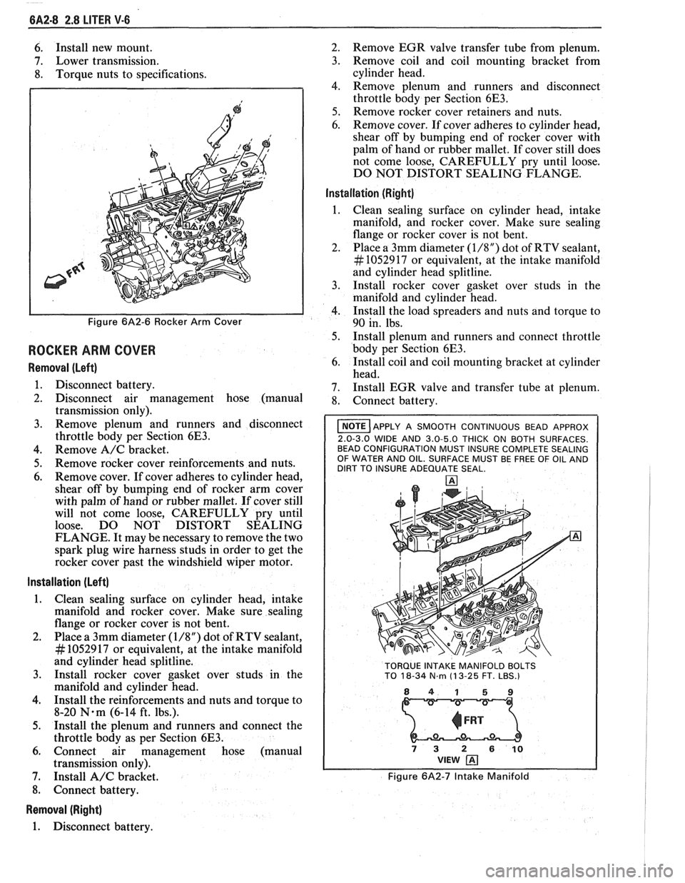
Figure 6A2-6 Rocker Arm Cover
ROCKER ARM COVER
Removal (Left)
1. Disconnect battery.
2. Disconnect air management hose (manual
transmission only).
3. Remove plenum and runners and disconnect
throttle body per Section
6E3.
4. Remove A/C bracket.
5. Remove rocker cover reinforcements and nuts.
6. Remove cover. If cover adheres to cylinder head,
shear off by bumping end of rocker arm cover
with palm of hand or rubber mallet. If cover still
will not come loose, CAREFULLY pry until
loose. DO NOT DISTORT SEALING
FLANGE. It may be necessary to remove the two
spark plug wire harness studs in order to get the
rocker cover past the windshield wiper motor.
Installation (Left)
1. Clean sealing surface on cylinder head, intake
manifold and rocker cover. Make sure sealing
flange or rocker cover is not bent.
2. Place a 3mm diameter
(1/8") dot of RTV sealant,
# 1052917 or equivalent, at the intake manifold
and cylinder head splitline.
3. Install rocker cover gasket over studs in the
manifold and cylinder head.
4. Install the reinforcements and nuts and torque to
8-20
N.m (6-14 ft. lbs.).
5. Install the plenum and runners and connect the
throttle body as per Section
6E3.
6. Connect air management hose (manual
transmission only).
7. Install
A/C bracket.
8. Connect battery.
Removal (Right)
1. Disconnect battery. 2.
Remove EGR valve transfer tube from plenum.
3. Remove coil and coil mounting bracket from
cylinder head.
4. Remove plenum and runners and disconnect
throttle body per Section
6E3.
5. Remove rocker cover retainers and nuts.
6. Remove cover. If cover adheres to cylinder head,
shear off by bumping end of rocker cover with
palm of hand or rubber mallet. If cover still does
not come loose, CAREFULLY pry until loose.
DO NOT DISTORT SEALING FLANGE.
Installation (Right)
Clean sealing surface on cylinder head, intake
manifold, and rocker cover. Make sure sealing
flange or rocker cover is not bent.
Place a 3mm diameter
(1/8") dot of RTV sealant,
# 1052917 or equivalent, at the intake manifold
and cylinder head splitline.
Install rocker cover gasket over studs in the
manifold and cylinder head.
Install the load spreaders and nuts and torque to
90 in. lbs.
Install plenum and runners and connect throttle
body per Section
6E3.
Install coil and coil mounting bracket at cylinder
head.
Install EGR valve and transfer tube at plenum.
Connect battery.
I NOTE ]APPLY A SMOOTH CONTINUOUS BEAD APPROX
2.0-3.0 WIDE AND 3.0-5.0 THICK ON BOTH SURFACES.
BEAD CONFIGURATION MUST INSURE COMPLETE SEALING
OF WATER AND OIL. SURFACE MUST BE FREE OF OIL AND
DIRT TO INSURE ADEQUATE SEAL.
TORQUE INTAKE MANIFOLD BOLTS
TO
18-34 N.m (1 3-25 FT. LBS.)
841 59
73 2 610 VIEW
Figure 6A2-7 Intake Manifold
Page 377 of 1825
6A2-26 2.8 LITER V-6
2. Remove the spark plugs. Installation
3. Remove
crankshaft pulley and torsional damper. 1. Install rear main bearing oil seal in cylinder block
4. Remove oil pan and oil pump. and
rear bearing cap grooves.
5. Remove water pump, crankcase front cover, 2. Lubricate seal with engine oil. Keep oil off
camshaft sprocket and timing chain. parting
line surface.
3. Install main bearings in cylinder block and main
6. Check the connecting rod caps for cylinder
bearing caps then lubricate bearing surface with
number identification. If necessary mark them.
engine oil.
7. Remove the connecting rod caps and
push the
4. 1n;tall crankshaft, being careful not to damage
pistons to top of bores.
bearing surfaces.
8. Remove main bearing caps and lift crankshaft out 5. Recheck bearing clearances using plastigage.
of cylinder block. 6.
Apply a thin coat of anaerobic sealant
# 1052357
9. Remove rear
main bearing oil seal and main or
equivalent to rear of the block mating surface
bearings from cylinder block and main bearing or corresponding
surface or rear main cap only.
caps. Do
not allow sealer on crankshaft or seal.
7. Install main bearing caps with arrow pointing
Cleaning and Inspection toward front of engine.
8. Torque all except
#3 main bearing cap bolts to
1. Wash crankshaft in solvent and dry with
specifications. Torque
#3 main bearing cap bolts
compressed air. to 14-16
N-m (10-12 lbs. ft.) then tap end of
2. Measure
dimensions of main bearing journals and crankshaft, first rearward then forward with a
crankpins with a micrometer for out-of-round, lead
hammer. This will line up rear main bearing
taper or undersize (See Specifications). and crankshaft
thrust surfaces.
Retorque all main
3. Check
crankshaft for run-out by supporting at bearing
cap bolts to specifications.
the front and rear main bearings journals in "V" 9. Measure crankshaft
end play with a feeler gage.
blocks and check at the front and rear Force crankshaft forward and measure clearance
intermediate journals with a dial indicator (See between the front of the
#3 main bearing and
Specifications). crankshaft thrust surface.
4. Replace or recondition the crankshaft if out of 10.
Install flywheel and torque to specifications.
specifications.
SPROCKET OR GEAR REPLACEMENT
Remove crankshaft sprocket using Tool J-5825,
install using Tool J-5590.
GENERAL DATA
TYPE .................................................................................................................................... 60" V-6
DISPLACEMENT
............................................................................................................. 2.8 Liter
RPO
........................................................................................................................................... LB8
BORE ......................................................................................................................................... 89
STROKE
................................... .... ............................................................................................... 76
COMPRESSION RATIO
....................................................................................................... 8.9: 1
FIRING ORDER
.......................................................................................................... 1-2-3-4-5-6
Cylinder Bore
DIAMETER .............................................................................................................. 88.992-88.070
OUT OF ROUND
............................................................................................................. .02 Max.
TAPER-THRUST SIDE
................................................................................................. .02 Max.
Piston
CLEARANCE .................................................................................................................. .O 17-,043
Piston Ring
Page 407 of 1825
6A3-28 V-8 ENGINE
16. Install
radiator and fan shroud and reconnect
radiator and heater hoses.
17. Fill cooling system.
18. Fill
crankcase with oil. See owner's manual for
specifications.
19. Install air cleaner.
20. Install hood.
21. Connect battery cables.
NOTICE: To avoid possible arcing of battery,
connect positive battery cable first.
22. Start engine, check for leaks and check timing.
CRANKSHAFT
The crankshaft can be removed while the engine
is disassembled for overhaul, as previously outlined, or
without complete disassembly.
Removal
With the engine removed from the vehicle and the
transmission and/or clutch housing removed
from the engine, mount engine in stand and
clamp securely.
Remove the oil dip stick and oil dip stick tube, (if
applicable).
Remove the starting motor, clutch assembly (if
equipped) and flywheel.
Remove the spark plugs.
Remove crankshaft pulley and torsional damper.
Remove oil pan and oil pump.
Remove crankcase front cover, and if so
equipped, remove timing chain and camshaft
sprocket.
Check the connecting rod caps for cylinder
number identification. If necessary, mark them.
Remove the connecting rod caps and push the
pistons to top of bores.
Remove main bearing caps and lift crankshaft out
of cylinder block.
Remove rear main bearing oil seal and main
bearings from cylinder block and main bearing
caps.
Cleaning and Inspection
1. Wash crankshaft in solvent and dry with
compressed air.
2. Measure dimensions of main bearing journals and
crankpins with a micrometer for out-of-round,
taper or undersize. (See Specifications.) 3.
Check crankshaft for run-out by supporting at
the front and rear main bearings journals in
"V"
blocks and check at the front and rear
intermediate journals with a dial indicator. (See
Specifications.)
4. Replace or recondition the crankshaft if out of
specifications.
SPROCKET OR GEAR REPLACEMENT
e Remove crankshaft sprocket using Tool
5-5825, install using Tool J-5590.
Installation
1.
Install rear main bearing oil seal in cylinder block
and rear main bearing cap grooves. Install with
lip of seal toward front of engine. Where seal has
two lips install lip with helix towards front of
engine.
2. Lubricate lips of seal with engine oil. Keep oil off
parting line surface.
3. Install main bearings in cylinder block and main
bearing caps then lubricate bearing surface with
engine oil.
4. Install crankshaft, being careful not to damage
bearing surfaces.
5. Recheck bearing clearances using plastigage.
6. Apply a thin coat of brush-on type oil sealing
compound to block mating surface and
corresponding surface of cap only. Do not allow
sealant on crankshaft or seal.
7. Install main bearing caps with arrows pointing
toward front of engine.
8. Torque all except rear main bearing cap bolts to
specifications. Torque rear main bearing cap bolts
to 10-12 lbs. ft. (14-16
N.m)then tap end of
crankshaft, first rearward then forward with a
lead hammer. This will line up rear main bearing
and crankshaft thrust surfaces.
Retorque all main
bearing cap bolts to specifications.
9. Measure crankshaft end play with a feeler gage.
Force crankshaft forward and measure clearance
between the front of the rear main bearing and the
crankshaft thrust surface.
10. Install flywheel and torque to specifications. A
wood block placed between the crankshaft and
cylinder block will prevent crankshaft from
rotating.
Align dowel hole in flywheel with dowel
hole in crankshaft. On vehicles equipped
with automatic transmissions, install
flywheel with the converter attaching pads
towards transmission.
GENERAL DATA
TYPE .................................................................................................................................. 90" V-8
DISPLACEMENT
............................................................................... 305 Cu. In., 350 Cu. In.
......................................................... LITER (VIN) ................................... ...... 5.0, (E), (F), 5.7 (8)
RPO ......................................................................................................................... L03, LB9, L98
BORE ........................................................................................................................ 3.736, 4.000
STROKE
........................... .. ....................................................................................... 3.480, 3.480
COMPRESSION RATIO
................................................................................... 931, 931, 9.5:1
FIRING ORDER .................................................................................................... 1-8-4-3-6-5-7-2
Page 890 of 1825
DRIVEABILITY AND EMISSIONS 5.OL (VIN F) & 5.7L (VIN 8) 6E3-CZ-3
Deceleration Mode
The ECM looks at changes in throttle position and
air flow to reduce the amount of fuel. When
deceleration is very fast, the ECM may shut off fuel
completely for short periods.
Battery Voltage Correction Mode
When battery voltage is low, the ECM can
compensate for the weak spark delivered by the
distributor by:
@ Increasing the amount of fuel delivered;
@ Increasing the idle rpm; and
@ Increasing ignition dwell time.
Fuel Cutoff Mode
No fuel is delivered by the injector when the
ignition is "OFF". This prevents dieseling. Also, fuel
is not delivered if no reference pulses are seen from
the distributor, which means the engine is not
running. This prevents flooding.
FUEL CONTROL SYSTEM
Basic System Operation
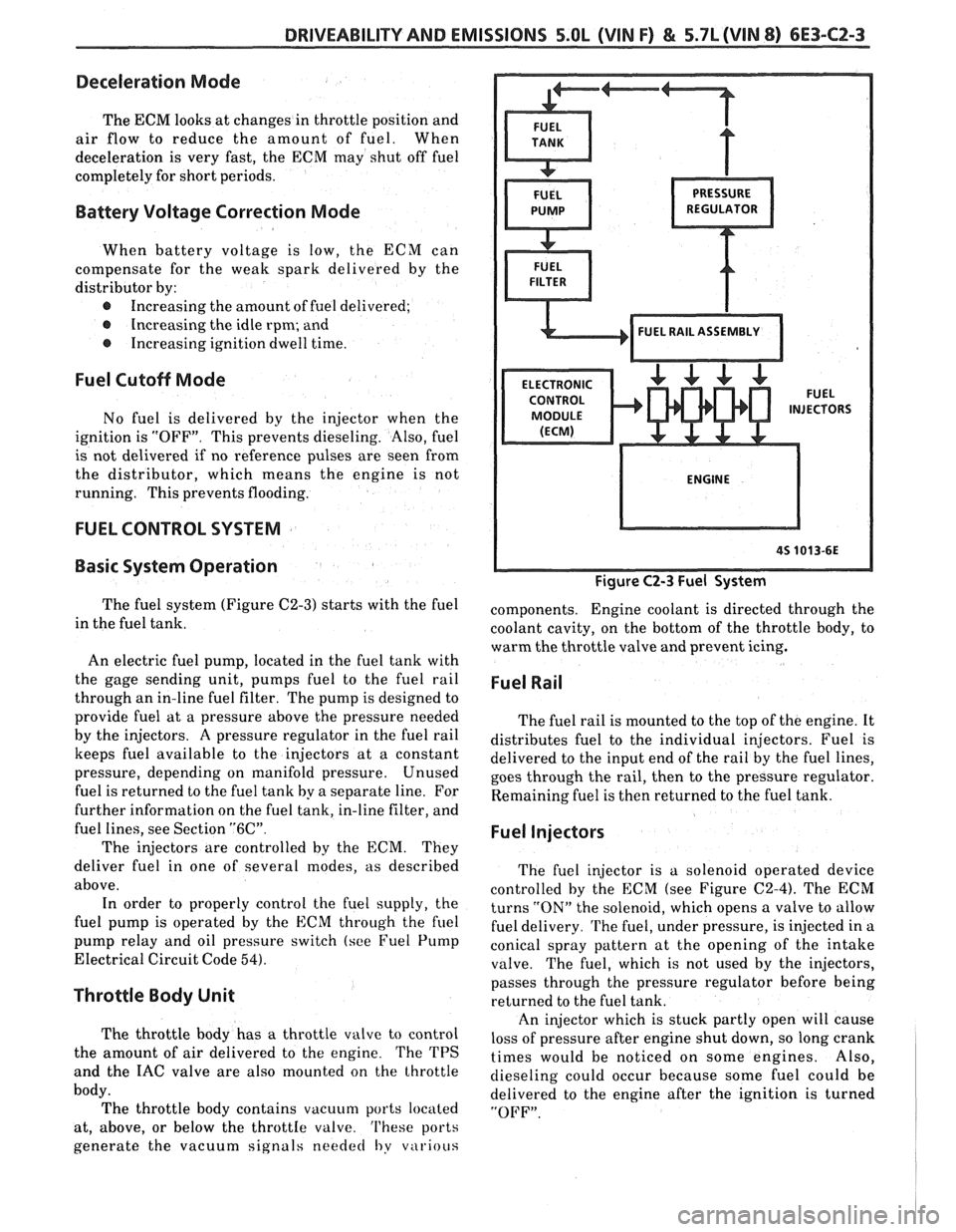
The fuel system (Figure C2-3) starts with the fuel
in the fuel tank.
An electric fuel pump, located in the fuel tank with
the gage sending unit, pumps
fuel to the fuel rail
through an in-line fuel filter. The pump is designed to
provide fuel at a pressure above the pressure needed
by the injectors. A pressure regulator in the fuel rail
keeps fuel available to the injectors at
a constant
pressure, depending on manifold pressure. Unused
fuel is returned to the fuel tank by a separate line. For
further information on the fuel tank, in-line filter, and
fuel lines, see Section
"6C".
The injectors are controlled by the ECM. They
deliver fuel in one of several modes, as described
above. In order to properly control the fuel supply, the
fuel pump is operated by the
ECM through the fuel
pump relay and oil pressure switch (see Fuel Pump
Electrical Circuit Code
54).
Throttle Body Unit
The throttle body has a throttle valve to control
the amount of air delivered to the engine. The TPS
and the IAC valve are also mounted on the throttle
body. The throttle body contains vacuum ports located
at, above, or below the
throttIe valve. 'I'hese ports
generate the vacuum signals
needed I,y v~irious
Figure C2-3 Fuel System
components. Engine coolant is directed through the
coolant cavity, on the bottom of the throttle body, to
warm the throttle valve and prevent icing.
Fuel Rail
The fuel rail is mounted to the top of the engine. It
distributes fuel to the individual injectors. Fuel is
delivered to the input end of the rail by the fuel lines,
goes through the rail, then to the pressure regulator.
Remaining fuel is then returned to the fuel tank.
Fuel Injectors
The fuel injector is a solenoid operated device
controlled by the ECM (see Figure
C2-4). The ECM
turns
"ON" the solenoid, which opens a valve to allow
fuel delivery.
The fuel, under pressure, is injected in a
conical spray pattern at the opening of the intake
valve. The fuel, which is not used by the injectors,
passes through the pressure regulator before being
returned to the fuel tank.
An injector which is stuck partly open will cause
loss of pressure after engine shut down, so long crank
times would be noticed on some engines. Also,
dieseling could occur because some fuel could be
delivered to the engine after the ignition is turned
"OFF".
Page 972 of 1825
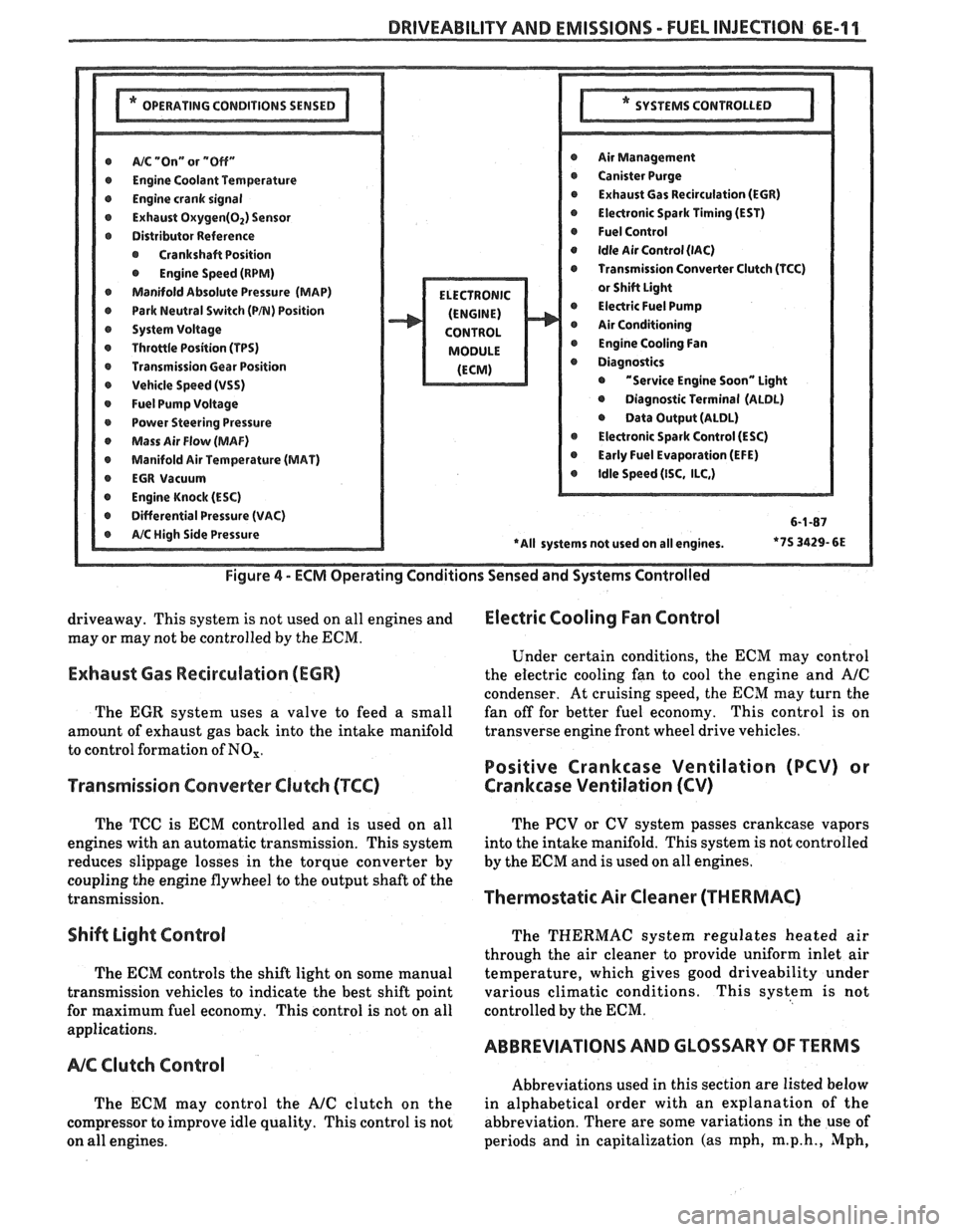
DRIVEABILITY AND EMISSIONS - FUEL INJEC"F0N 6E-11
@ A/% "On" or "Off" r Air Management
r Engine Coolant Temwrature r Canister Purge
@ Engine crank signal r Exhaust Gas Recirculation (EGR)
@ Exhaust Oxygen(02) Sensor @ Electronic Spark Timing (EST)
r Distributor Reference @ Fuel Control
@ Crankshaft Position @ Idle Air Control (lAC)
@ Engine Speed (RPM) Transmission Converter Clutch (TCC)
Manifold Absolute Pressure (MAP)
@ Park Neutral Switch (PB) Position @ Electric Fuel Pump
r System Voltage Air Conditioning
r Throttle Position (TPS) @ Engine Cooling Fan
r Transmission Gear Position
r Vehicle Speed (VSS) @ "Service Engine Soon" Light
@ Fuel Pump Voltage @ Diagnostic Terminal (ALDL)
r Power Steering Pressure @ Data Output (ALDL)
Mass Air Flow (MAF) @ Electronic Spark Control (ESC)
@ Manifold Air Temperature (MAT) @ Early Fuel Evaporation (EFE)
r EGR Vacuum @ Idle Speed (ISC, ILC,)
@ Engine Knock (ESC)
r Differential Pressure (VAC) 6-1-87
*7S
3429- 6E
Figure
4 - ECM Operating Conditions Sensed and Systems Controlled
driveaway. This system is not used on all engines and Electric Cooling Fan Control
may or may not be controlled by the ECM.
Under certain conditions, the
ECM may control
Exhaust Gas Recirculation (ECR) the electric cooling fan to cool the engine and A/C
condenser. At cruising speed, the ECM may turn the
The
EGR system uses a valve to feed a small fan
off for better fuel economy. This control is on
amount of exhaust gas back into the intake manifold transverse
engine front wheel drive vehicles.
to control formation of
NO,.
Positive Crankcase Ventilation (PCV) or
Transmission Converter
Clutch (TCC) Crankcase Ventilation (CV)
The TCC is ECM controlled and is used on all
engines with an automatic transmission. This system
reduces slippage losses in the torque converter by
coupling the engine flywheel to the output shaft of the
transmission.
Shift Light Control
The ECM controls the shift light on some manual
transmission vehicles to indicate the best shift point
for maximum fuel economy. This control is not on all
applications.
NC Clutch Control
The ECM may control the AJC clutch on the
compressor to improve idle quality. This control is not
on all engines. The
PCV or CV system passes crankcase vapors
into the intake manifold. This system is not controlled
by the
ECM and is used on all engines.
Thermostatic Air Cleaner (THERMAC)
The THERMAC system regulates heated air
through the air cleaner to provide uniform inlet air
temperature, which gives good driveability under
various climatic conditions. This system is not
controlled by the
ECM.
ABBREVIATIONS AND GLOSSARY OF TERMS
Abbreviations used in this section are listed below
in alphabetical order with an explanation of the
abbreviation. There are some variations in the use of
periods and in capitalization (as mph,
m.p.h., Mph,
Page 1553 of 1825
RADIO I
(Continued from previous page) from back of Radio
If noise persists with replacement antenna, the
problem must be repaired at the source of noise
(generator, ignition system, accessory, etc.). See
Delco Manual for noise "Sniffing" procedures.
Ignition Noise
Trv the following. fixes in the piven order: 8. Install a braided ground strap on the hood. Replace
defective antenna with a good antenna.
If noise disappears repair or replace the defective
antenna. Check antenna ground, Coaxial Cable
Braid, and ground at connectors.
unplugged
- -
1. Check
for loose or defective spark plug wire.
2. Check for defective spark plug.
3. Move all wiring away from Ignition System
and spark plug wires. Antenna
noise
4. Reroute spark plug wires laying against
anything that could possibly transmit noise
to the Radio (car
g or sensor leads that
travel into the passenger compartment).
5. Inspect Ignition system for the following
and replace if necessary:
r Distributor cap carbon ball eroded away,
cracked or loose cap.
A rotor with burned black spot on wiper or
pits in wiper surface.
r A defective coil.
r An oily film on some of the lead terminals or
inside the cap.
Defective
WE1 module; can cause ignition
noise on
FM only.
6. Replace distributor cap and rotor.
9. Check Heater Core ground; clean or install a
braided ground strap if necessary.
10. Check air conditioner accumulator ground;
clean or install a braided ground strap if
necessarv.
TO STEERING
BRAIDED
GROUN GO LUMN
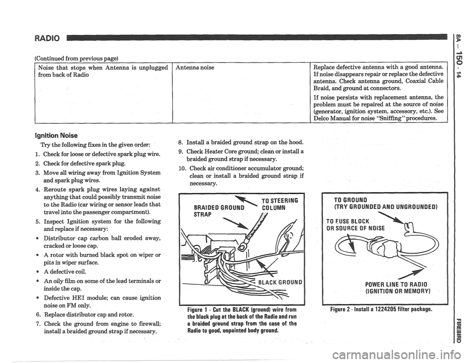
Figure 1 - Gut the BLACK (ground) wire from
the black plug
at the back of the Radio and run
7. Check the ground from engine to firewall, a braided ground strap from the ease of the
install a braided ground strap if necessary. Radio to good, unpainted body ground.
(TRY GROUNDED AND UNGROUNDED)
POWER LlNE TO RADIO
(IGNITION OR MEMORY)
Figure 2 - install a 1224205 filter package.