PORSCHE 911 TURBO 2014 6.G Owners Manual
Manufacturer: PORSCHE, Model Year: 2014, Model line: 911 TURBO, Model: PORSCHE 911 TURBO 2014 6.GPages: 300, PDF Size: 10.61 MB
Page 261 of 300
Minor Repairs 259
If a wheel needs to be changed, the procedure described below must be adhered to exactly, as otherwise the wheel may loosen, resulting in damage. Porsche cannot be held liable if this happens.To achieve the high tightening torque required for the central bolt, a suitable, commercially available 443 ftlb. (600 Nm) torque wrench must be used. Alternatively, a corresponding tool with torque multiplier (part no. 997.450.323.90) is available from Porsche Motorsport. When a torque multiplier is used, the torque must be reduced in accordance with the tool’s operating instructions.
When loosening and fastening the wheel, a second person is needed to prevent the wheel from turning by firmly braking it.
The high mounting forces involved can cause the vehicle to roll away and slip off the jack.fAlways use a lifting platform if there is one available.
Risk of damage due to vehicle tipping over or falling off lifting equipment or using the wrong tool.
The high mounting forces involved can cause the vehicle to roll away and slip off the jack. An impact wrench can damage the central lock.fAlways use a lifting platform if there is one available.fDo not use an impact wrench .
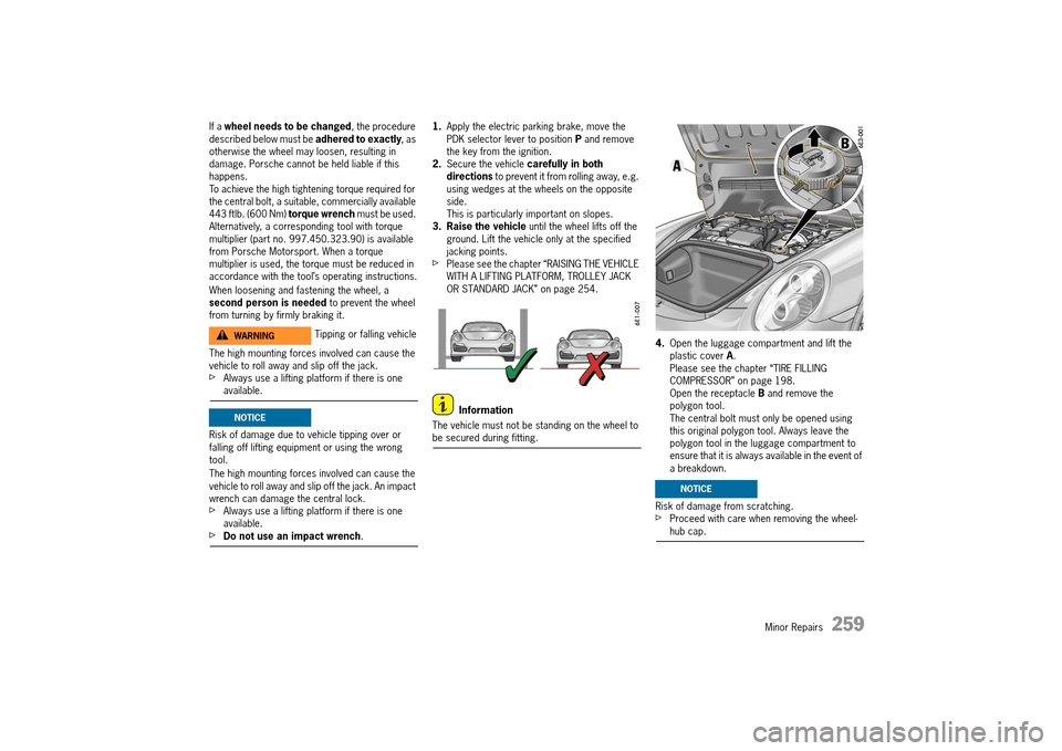
1. Apply the electric parking brake, move the PDK selector lever to position P and remove the key from the ignition.2. Secure the vehicle carefully in both directions to prevent it from rolling away, e.g. using wedges at the wheels on the opposite side.This is particularly important on slopes.3. Raise the vehicle until the wheel lifts off the ground. Lift the vehicle only at the specified jacking points.fPlease see the chapter “RAISING THE VEHICLE WITH A LIFTING PLATFORM, TROLLEY JACK OR STANDARD JACK” on page 254.
Information
The vehicle must not be standing on the wheel to be secured during fitting.
4. Open the luggage compartment and lift the plastic cover A. Please see the chapter “TIRE FILLING COMPRESSOR” on page 198.Open the receptacle B and remove the polygon tool.The central bolt must only be opened using this original polygon tool. Always leave the polygon tool in the luggage compartment to ensure that it is always available in the event of a breakdown.
Risk of damage from scratching.fProceed with care when removing the wheel-hub cap.
Tipping or falling vehicleWARNINGh
NOTICE
NOTICE
14_991_Turbo_21.book Seite 259 Mittwoch, 9. April 2014 2:19 14
Page 262 of 300
260 Minor Repairs
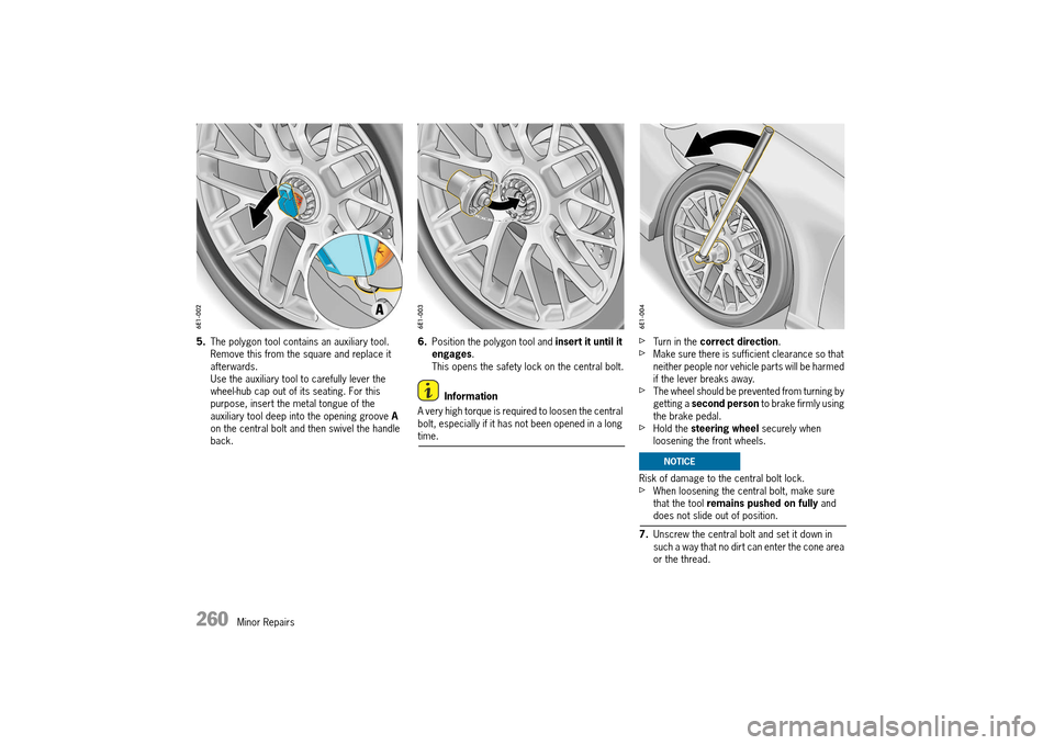
5.The polygon tool contains an auxiliary tool. Remove this from the square and replace it afterwards.Use the auxiliary tool to carefully lever the wheel-hub cap out of its seating. For this purpose, insert the metal tongue of the auxiliary tool deep into the opening groove A on the central bolt and then swivel the handle back.
6. Position the polygon tool and insert it until it engages . This opens the safety lock on the central bolt.
Information
A very high torque is required to loosen the central bolt, especially if it has not been opened in a long time.
fTurn in the correct direction.fMake sure there is sufficient clearance so that neither people nor vehicle parts will be harmed if the lever breaks away.fThe wheel should be prevented from turning by getting a second person to brake firmly using the brake pedal.fHold the steering wheel securely when loosening the front wheels.
Risk of damage to the central bolt lock.fWhen loosening the central bolt, make sure that the tool remains pushed on fully and does not slide out of position.
7. Unscrew the central bolt and set it down in such a way that no dirt can enter the cone area or the thread.
NOTICE
14_991_Turbo_21.book Seite 260 Mittwoch, 9. April 2014 2:19 14
Page 263 of 300
Minor Repairs 261
There is a risk of damage to brake disks on vehicles with Porsche Ceramic Composite Brake (PCCB).fDo not tilt the wheel when removing it.
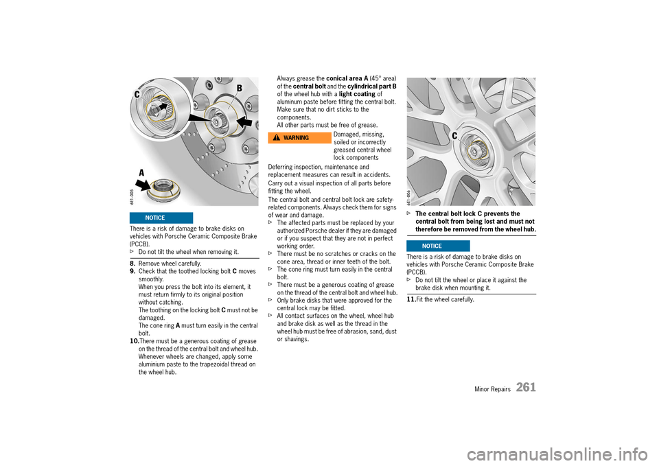
8. Remove wheel carefully. 9. Check that the toothed locking bolt C moves smoothly.When you press the bolt into its element, it must return firmly to its original position without catching.The toothing on the locking bolt C must not be damaged.The cone ring A must turn easily in the central bolt.10. There must be a generous coating of grease on the thread of the central bolt and wheel hub. Whenever wheels are changed, apply some aluminium paste to the trapezoidal thread on the wheel hub.
Always grease the conical area A (45° area) of the central bolt and the cylindrical part B of the wheel hub with a light coating of aluminum paste before fitting the central bolt. Make sure that no dirt sticks to the components.All other parts must be free of grease.
Deferring inspection, maintenance and replacement measures can result in accidents.
Carry out a visual inspection of all parts before fitting the wheel.
The central bolt and central bolt lock are safety- related components. Always check them for signs of wear and damage.fThe affected parts must be replaced by your authorized Porsche dealer if they are damaged or if you suspect that they are not in perfect working order.fThere must be no scratches or cracks on the cone area, thread or inner teeth of the bolt.fThe cone ring must turn easily in the central bolt.fThere must be a generous coating of grease on the thread of the central bolt and wheel hub.fOnly brake disks that were approved for the central lock may be fitted.fAll contact surfaces on the wheel, wheel hub and brake disk as well as the thread in the wheel hub must be free of abrasion, sand, dust or shavings.
fThe central bolt lock C prevents the central bolt from being lost and must not therefore be removed from the wheel hub.
There is a risk of damage to brake disks on vehicles with Porsche Ceramic Composite Brake (PCCB).fDo not tilt the wheel or place it against the brake disk when mounting it.
11. Fit the wheel carefully.
NOTICE
Damaged, missing, soiled or incorrectly greased central wheel lock components
WARNINGh
NOTICE
14_991_Turbo_21.book Seite 261 Mittwoch, 9. April 2014 2:19 14
Page 264 of 300
262 Minor Repairs
Information
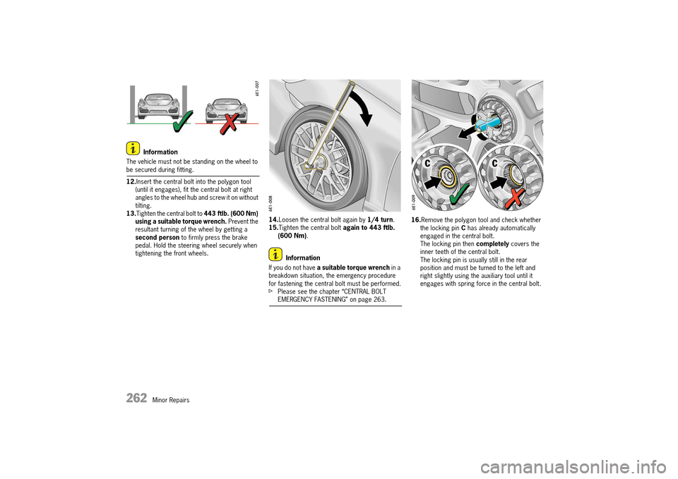
The vehicle must not be standing on the wheel to be secured during fitting.
12. Insert the central bolt into the polygon tool (until it engages), fit the central bolt at right angles to the wheel hub and screw it on without tilting.13.Tighten the central bolt to 443 ftlb. (600 Nm) using a suitable torque wrench. Prevent the resultant turning of the wheel by getting a second person to firmly press the brake pedal. Hold the steering wheel securely when tightening the front wheels.
14. Loosen the central bolt again by 1/4 turn. 15. Tighten the central bolt again to 443 ftlb. (600 Nm) .
Information
If you do not have a suitable torque wrench in a breakdown situation, the emergency procedure for fastening the central bolt must be performed.fPlease see the chapter “CENTRAL BOLT EMERGENCY FASTENING” on page 263.
16. Remove the polygon tool and check whether the locking pin C has already automatically engaged in the central bolt. The locking pin then completely covers the inner teeth of the central bolt. The locking pin is usually still in the rear position and must be turned to the left and right slightly using the auxiliary tool until it engages with spring force in the central bolt.
14_991_Turbo_21.book Seite 262 Mittwoch, 9. April 2014 2:19 14
Page 265 of 300
Minor Repairs 263
Deferring inspection measures can result in accidents.fNever drive when the locking pin is not engaged.
Risk of damage due to central bolt lock not engaging.fNever drive when the locking pin is not engaged.
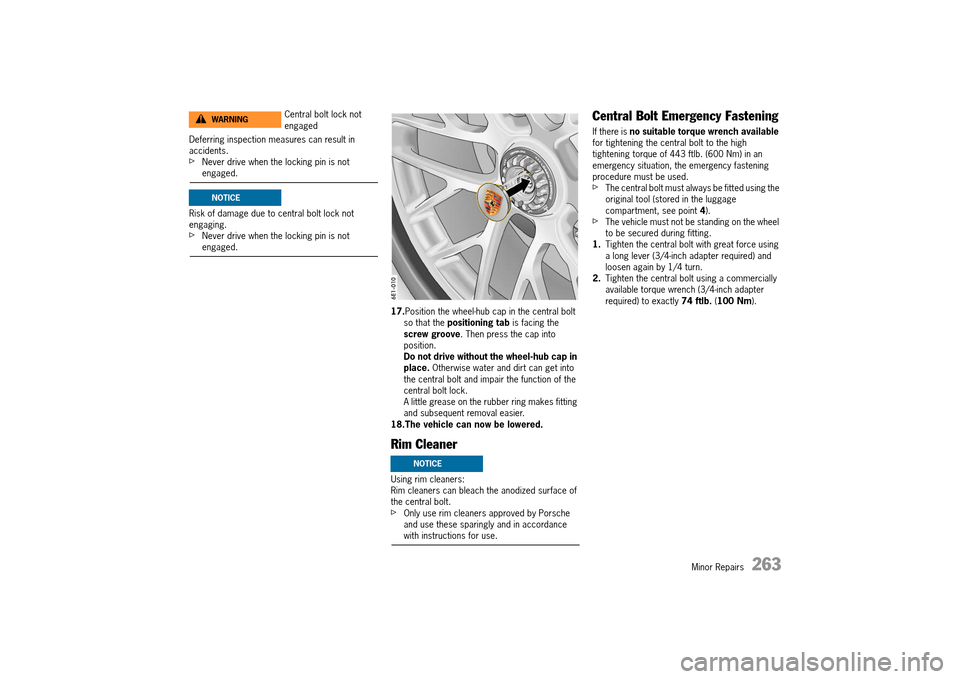
17. Position the wheel-hub cap in the central bolt so that the positioning tab is facing the screw groove . Then press the cap into position.Do not drive without the wheel-hub cap in place. Otherwise water and dirt can get into the central bolt and impair the function of the central bolt lock.A little grease on the rubber ring makes fitting and subsequent removal easier.18.The vehicle can now be lowered.
Rim Cleaner
Using rim cleaners: Rim cleaners can bleach the anodized surface of the central bolt.fOnly use rim cleaners approved by Porsche and use these sparingly and in accordance with instructions for use.
Central Bolt Emergency Fastening
If there is no suitable torque wrench available for tightening the central bolt to the high tightening torque of 443 ftlb. (600 Nm) in an emergency situation, the emergency fastening procedure must be used.fThe central bolt must always be fitted using the original tool (stored in the luggage compartment, see point 4).fThe vehicle must not be standing on the wheel to be secured during fitting.1. Tighten the central bolt with great force using a long lever (3/4-inch adapter required) and loosen again by 1/4 turn.2. Tighten the central bolt using a commercially available torque wrench (3/4-inch adapter required) to exactly 74 ftlb. (100 Nm).
Central bolt lock not engagedWARNINGh
NOTICE
NOTICE
14_991_Turbo_21.book Seite 263 Mittwoch, 9. April 2014 2:19 14
Page 266 of 300
264 Minor Repairs
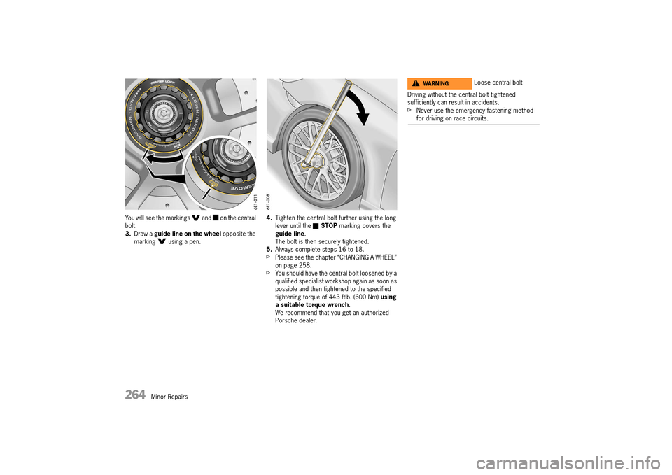
You will see the markings and on the central bolt.3. Draw a guide line on the wheel opposite the marking using a pen.
4. Tighten the central bolt further using the long lever until the STOP marking covers the guide line . The bolt is then securely tightened.5. Always complete steps 16 to 18.fPlease see the chapter “CHANGING A WHEEL” on page 258.fYou should have the central bolt loosened by a qualified specialist workshop again as soon as possible and then tightened to the specified tightening torque of 443 ftlb. (600 Nm) using a suitable torque wrench . We recommend that you get an authorized Porsche dealer.
Driving without the central bolt tightened sufficiently can result in accidents.fNever use the emergency fastening method for driving on race circuits.
Loose central boltWARNINGh
14_991_Turbo_21.book Seite 264 Mittwoch, 9. April 2014 2:19 14
Page 267 of 300
Minor Repairs 265
Flat Tire
1.Stop the vehicle as far away from the driving lane as possible.The vehicle must be parked on a firm and flat surface offering adequate grip.2. Switch emergency flasher on. 3. Apply the parking brake. 4. Move the PDK selector lever to position P. 5. Straighten the front wheels. 6. Remove the ignition key, or the control unit on vehicles with Porsche Entry & Drive, in order to lock the steering and prevent the engine from being started.7. Get all passengers to leave the vehicle. 8. Set up the warning triangle at a suitable distance.
Filling in tire sealant
The tire sealant can be found in the right-hand box in the luggage compartment. The compressor is located under the cover in the luggage compartment.
The tire sealant can be used to seal small cuts, especially in the tire tread.
Sealing the tire with the tire sealant is only an emergency solution so you can drive to the nearest workshop. Even if the tire is air-tight, it may only be used for short journeys in an emergency.
The tire sealant set comprises: – a filler bottle– a filler hose– a valve turner– a spare valve insert– a sticker with the maximum permitted speed– a compressor– operating instructions
Always observe the following points:fUse the tire sealant only in the case of cuts or punctures no larger than 0.15 in. (4 mm).fNever use the tire sealant if the rim is damaged.
The sealant is highly flammable and harmful to health.fFire, naked flame and smoking are prohibited when handling tire sealant.fAvoid contact with skin, eyes or clothing due to caustic chemical properties of the tire sealant.fKeep tire sealant away from children.fDo not inhale vapors, due to the consequent harm to personal health resulting in serious personal injury or death.
In the event of contact with sealant:
fIf sealant gets on your skin or into your eyes, thoroughly rinse the affected part of your body immediately with plenty of water.fChange soiled clothing immediately.fSee a doctor immediately in the event of an allergic reaction.fIf sealant is swallowed, thoroughly rinse out the mouth without delay and drink plenty of water. Do not induce vomiting.See a doctor immediately.
Limits on Tire Sealant Use
Tire Sealant Flammability
WARNINGh
WARNINGh
14_991_Turbo_21.book Seite 265 Mittwoch, 9. April 2014 2:19 14
Page 268 of 300
266 Minor Repairs
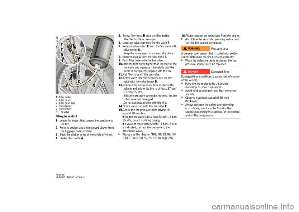
A- Filler bottle B - Filler hose C - Filler hose plug D - Valve turner E - Valve insert F - Tire valve
Filling in sealant
1. Leave the object that caused the puncture in the tire.2. Remove sealant and the enclosed sticker from the luggage compartment.3. Stick the sticker in the driver’s field of vision. 4. Shake filler bottle A.
5. Screw filler hose B onto the filler bottle. The filler bottle is now open.6. Unscrew valve cap from the tire valve F. 7. Remove valve insert E from the tire valve with valve turner D. Keep the valve insert in a clean, dry place.8. Remove plug C from the filler hose B. 9. Push filler hose onto the tire valve. 10. Hold the filler bottle higher than the level of the tire valve and squeeze it forcefully until the bottle is completely emptied into the tire.11. Pull filler hose off the tire valve. 12. Screw valve insert E securely into the tire valve with the valve turner D. 13. Connect the compressor to a socket in the vehicle and inflate the tire to at least 37 psi/2.5 bar/25 kPa.If this tire pressure cannot be reached, the tire is too severely damaged.Do not continue driving with this tire.14. Screw valve cap onto the tire valve F. 15. Check the tire pressure after driving for around 10 minutes.If the tire pressure is less than 22 psi/1.5 bar/15 kPa, do not continue driving.If a value of more than 22 psi/1.5 bar/15 kPa is indicated, correct the pressure to the prescribed value.fPlease see the chapter “TIRE PRESSURE FOR COLD TIRES (68 °F/ 20 °C)” on page 287.
16. Please contact an authorized Porsche dealer.fAlso follow the separate operating instructions for the tire sealing compound.
A tire pressure sensor that is soiled with sealant cannot determine the tire pressure correctly.fWhen the defective tire is replaced, the tire pressure sensor must be replaced.
Damaged tires could burst causing loss of control of the vehicle.fHave the tire replaced by a specialist workshop as soon as possible.fAvoid hard acceleration and high cornering speeds.fObserve maximum speed of 50 mph (80 km/h).fAlways observe the safety and operating instructions, which can be found in the separate operating instructions for the sealant and on the compressor.
Pressure Loss
Damaged Tires
WARNINGh
DANGERh
14_991_Turbo_21.book Seite 266 Mittwoch, 9. April 2014 2:19 14
Page 269 of 300
Minor Repairs 267
Electrical System
In order to avoid damage and faults in electrical or electronic systems, electrical accessories should be installed at an authorized Porsche dealerfUse only accessories approved by Porsche.
Replacing fuses or relays with the engine running or the ignition on could cause electrical shock.fDisconnect the negative terminal on the battery during all work on the electrical system.fPlease see the chapter “BATTERY (12 VOLT)” on page 271.
Relays
Relays should be checked or changed only at an authorized workshop.
Changing fuses
In order to prevent damage to the electrical system due to short circuits and overloads, the individual circuits are protected by fuses.
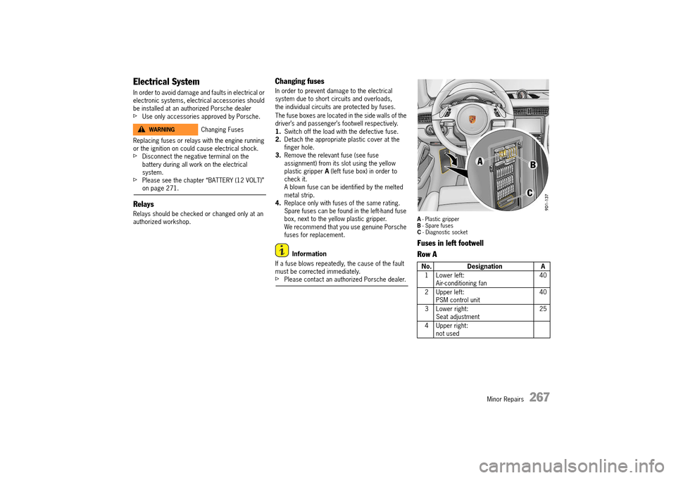
The fuse boxes are located in the side walls of the driver’s and passenger’s footwell respectively. 1. Switch off the load with the defective fuse. 2. Detach the appropriate plastic cover at the finger hole.3. Remove the relevant fuse (see fuse assignment) from its slot using the yellow plastic gripper A (left fuse box) in order to check it.A blown fuse can be identified by the melted metal strip.4. Replace only with fuses of the same rating. Spare fuses can be found in the left-hand fuse box, next to the yellow plastic gripper.We recommend that you use genuine Porsche fuses for replacement.
Information
If a fuse blows repeatedly, the cause of the fault must be corrected immediately.fPlease contact an authorized Porsche dealer.
A - Plastic gripper B - Spare fuses C - Diagnostic socket
Fuses in left footwell
Row A
Changing FusesWARNINGh
No. Designation A
1 Lower left: Air-conditioning fan 40
2 Upper left: PSM control unit 40
3 Lower right: Seat adjustment 25
4 Upper right: not used
14_991_Turbo_21.book Seite 267 Mittwoch, 9. April 2014 2:19 14
Page 270 of 300
268 Minor Repairs
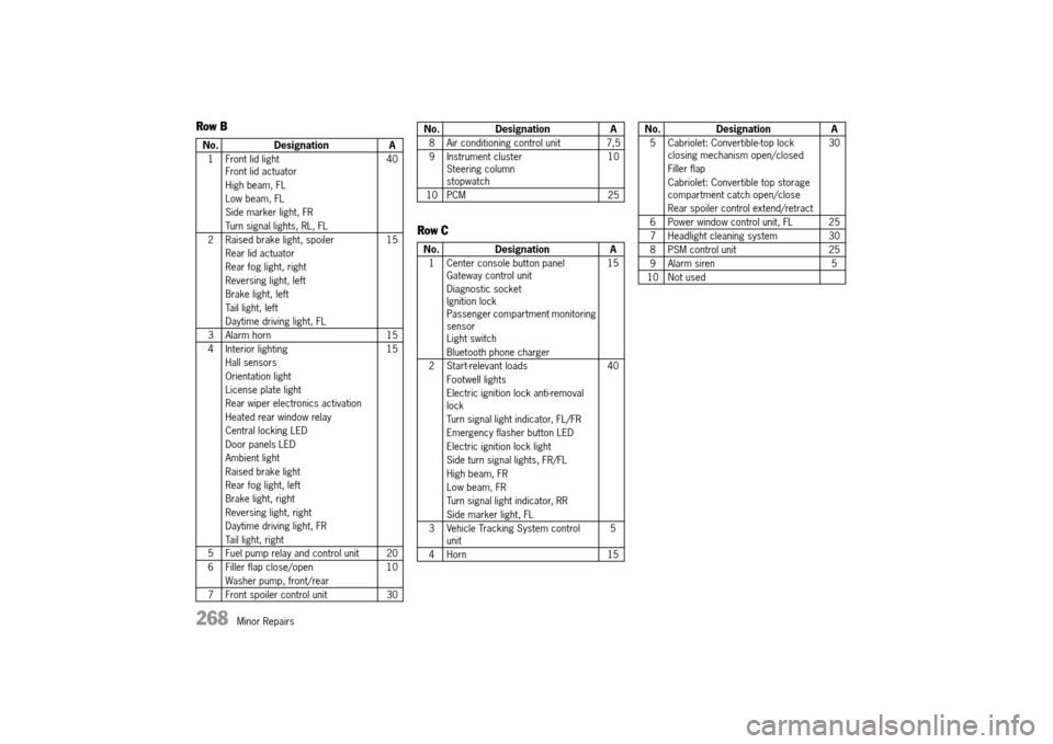
Row B
Row C
No. Designation A
1 Front lid light Front lid actuator
High beam, FL
Low beam, FL
Side marker light, FR
Turn signal lights, RL, FL
40
2 Raised brake light, spoiler
Rear lid actuator
Rear fog light, right
Reversing light, left
Brake light, left
Tail light, left
Daytime driving light, FL
15
3 Alarm horn 15
4 Interior lighting
Hall sensors
Orientation light
License plate light
Rear wiper electronics activation
Heated rear window relay
Central locking LED
Door panels LED
Ambient light
Raised brake light
Rear fog light, left
Brake light, right
Reversing light, right
Daytime driving light, FR
Tail light, right
15
5 Fuel pump relay and control unit 20
6 Filler flap close/open
Washer pump, front/rear
10
7 Front spoiler control unit 30
8 Air conditioning control unit 7,5
9 Instrument cluster Steering columnstopwatch
10
10 PCM 25
No. Designation A
1 Center console button panel Gateway control unit
Diagnostic socket Ignition lock Passenger compartment monitoring sensorLight switch
Bluetooth phone charger
15
2 Start-relevant loads
Footwell lights
Electric ignition lock anti-removal lock
Turn signal light indicator, FL/FR
Emergency flasher button LED
Electric ignition lock light
Side turn signal lights, FR/FL
High beam, FR
Low beam, FR
Turn signal light indicator, RR
Side marker light, FL
40
3 Vehicle Tracking System control unit 5
4 Horn 15
No. Designation A
5 Cabriolet: Convertible-top lock closing mechanism open/closed
Filler flap
Cabriolet: Convertible top storage compartment catch open/close
Rear spoiler control extend/retract
30
6 Power window control unit, FL 25
7 Headlight cleaning system 30
8 PSM control unit 25
9 Alarm siren 5
10 Not used
No. Designation A
14_991_Turbo_21.book Seite 268 Mittwoch, 9. April 2014 2:19 14