display Ram 1500 2020 Owner's Manual
[x] Cancel search | Manufacturer: RAM, Model Year: 2020, Model line: 1500, Model: Ram 1500 2020Pages: 674, PDF Size: 32.69 MB
Page 419 of 674

STARTING AND OPERATING 417
GAIN Adjustment Buttons (+/-)
Pushing these buttons will adjust the brake control power
output to the trailer brakes in 0.5 increments. The GAIN
setting can be increased to a maximum of 10 or decreased to
a minimum of 0 (no trailer braking).
GAIN
The GAIN setting is used to set the trailer brake control for
the specific towing condition and should be changed as
towing conditions change. Changes to towing conditions
include trailer load, vehicle load, road conditions and
weather.
Adjusting GAIN
NOTE:
This should only be performed in a traffic free environment
at speeds of approximately 20–25 mph (30–40 km/h).
1. Make sure the trailer brakes are in good working condi-
tion, functioning normally and properly adjusted. See
your trailer dealer if necessary.
2. Hook up the trailer and make the electrical connections according to the trailer manufacturer's instructions.
3. When a trailer with electric/EOH brakes is plugged in, the trailer connected message should appear in the
instrument cluster display (if the connection is not recog -nized by the ITBM, braking functions will not be avail
-
able), the GAIN setting will illuminate and the correct
type of trailer must be selected from the instrument
cluster display options.
4. Push the UP or DOWN button on the steering wheel until “TRAILER TOW” appears on the screen.
5. Push the RIGHT arrow on the steering wheel to enter “TRAILER TOW”.
6. Push the UP or DOWN buttons until the Trailer Brake Type appears on the screen.
7. Push the RIGHT arrow and then push the UP or DOWN buttons until the proper Trailer Brake Type appears on
the screen.
8. In a traffic-free environment, tow the trailer on a dry, level surface at a speed of 20–25 mph (30–40 km/h) and
squeeze the manual brake control lever completely.
9. If the trailer wheels lockup (indicated by squealing tires), reduce the GAIN setting; if the trailer wheels turn freely,
increase the GAIN setting.
Repeat steps 8 and 9 until the GAIN setting is at a point just
below trailer wheel lockup. If towing a heavier trailer, trailer
wheel lockup may not be attainable even with the maximum
GAIN setting of 10.
5
2020_DT_1500_OM_US.book Page 417
Page 420 of 674

418 STARTING AND OPERATING
*The suggested selection depends and may change
depending on the customer preferences for braking perfor-
mance. Condition of the trailer brakes, driving and road state
may also affect the selection.
Display Messages
The trailer brake control interacts with the instrument cluster
display. Display messages, along with a single chime, will be
displayed when a malfunction is determined in the trailer
connection, trailer brake control, or on the trailer. Refer to
“Instrument Cluster Display” in “Getting To Know Your
Instrument Panel” for further information. NOTE:
• An aftermarket controller may be available for use with
trailers with air or electric-over-hydraulic trailer brake
systems. To determine the type of brakes on your trailer
and the availability of controllers, check with your trailer
manufacturer or dealer.
• Removal of the ITBM will cause errors and it may cause damage to the electrical system and electronic modules of
the vehicle. See your authorized dealer if an aftermarket
module is to be installed.
Light Electric Heavy Electric
Light EOHHeavy EOH
Type of Trailer Brakes Electric Trailer Brakes Electric Trailer Brakes Electric over Hydraulic
Trailer BrakesElectric over Hydraulic
Trailer Brakes
Load *Under 10,000 lbs *Above 10,000 lbs *Under 10,000 lbs *Above 10,000 lbs
WARNING!
Connecting a trailer that is not compatible with the
ITBM system may result in reduced or complete loss of
trailer braking. There may be a increase in stopping
distance or trailer instability which could result in
personal injury.
CAUTION!
Connecting a trailer that is not compatible with the
ITBM system may result in reduced or complete loss of
trailer braking. There may be a increase in stopping
distance or trailer instability which could result in
damage to your vehicle, trailer, or other property.
2020_DT_1500_OM_US.book Page 418
Page 433 of 674
431
IN CASE OF EMERGENCY
HAZARD WARNING FLASHERS
The Hazard Warning switch is located on the upper
switch bank just below the radio.
NOTE:
If your vehicle is equipped with a 12–inch Uconnect display,
the Hazard Warning switch is located above the display.
Push the switch to turn on the Hazard Warning flasher.
When the switch is activated, all directional turn signals will
flash on and off to warn oncoming traffic of an emergency.
Push the switch a second time to turn off the Hazard
Warning flashers.
This is an emergency warning system and it should not be
used when the vehicle is in motion. Use it when your vehicle
is disabled and it is creating a safety hazard for other motor -
ists.
When leaving the vehicle to seek assistance, the Hazard
Warning flashers will continue to operate even though the
ignition is placed in the OFF position. NOTE:
With extended use the Hazard Warning flashers may wear
down your battery.
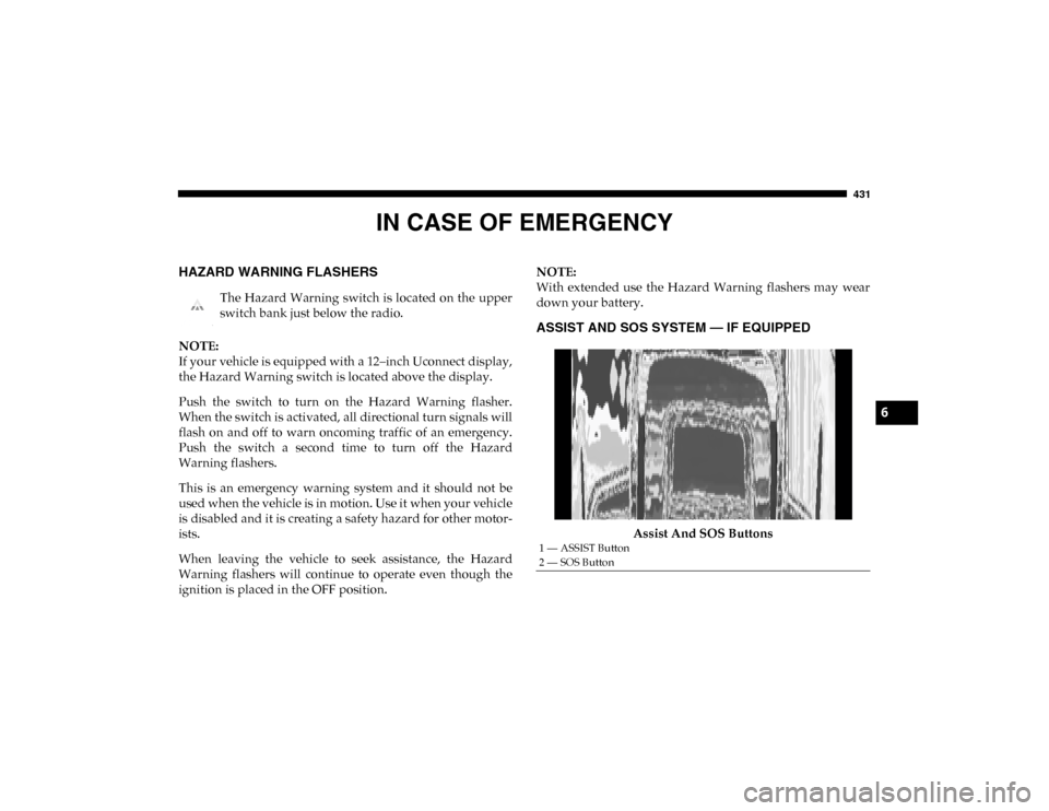
ASSIST AND SOS SYSTEM — IF EQUIPPED
Assist And SOS Buttons
1 — ASSIST Button
2 — SOS Button
6
2020_DT_1500_OM_US.book Page 431
Page 436 of 674
434 IN CASE OF EMERGENCY
(Continued)
SOS Call System Limitations
Vehicles sold in Mexico DO NOT have SOS Call system
capabilities.
SOS or other emergency line operators in Mexico may not
answer or respond to SOS system calls.
If the SOS Call system detects a malfunction, any of the
following may occur at the time the malfunction is detected,
and at the beginning of each ignition cycle:
• The overhead console light located between the ASSIST and SOS buttons will continuously be illuminated red.
• The Device Screen will display the following message: “Vehicle device requires service. Please contact your
dealer.”
• An In-Vehicle Audio message will state “Vehicle device requires service. Please contact your dealer.”
• Never place anything on or near the vehicle’s operable
network and GPS antennas. You could prevent oper -
able network and GPS signal reception, which can
prevent your vehicle from placing an emergency call.
An operable network and GPS signal reception is
required for the SOS Call system to function properly.
• The SOS Call system is embedded into the vehicle’s electrical system. Do not add aftermarket electrical
equipment to the vehicle’s electrical system. This may
prevent your vehicle from sending a signal to initiate
an emergency call. To avoid interference that can cause
the SOS Call system to fail, never add aftermarket
equipment (e.g., two-way mobile radio, CB radio, data
recorder, etc.) to your vehicle’s electrical system or
modify the antennas on your vehicle. IF YOUR
VEHICLE LOSES BATTERY POWER FOR ANY
REASON (INCLUDING DURING OR AFTER AN
ACCIDENT), THE UCONNECT FEATURES, APPS
AND SERVICES, AMONG OTHERS, WILL NOT
OPERATE.
• Modifications to any part of the SOS Call system could cause the air bag system to fail when you need it. You
could be injured if the air bag system is not there to
help protect you.WARNING! (Continued)
WARNING!
• Ignoring the overhead console light could mean you will not have SOS Call services. If the overhead console
light is illuminated, have your authorized dealer
service the SOS Call system immediately.
2020_DT_1500_OM_US.book Page 434
Page 484 of 674

482
SERVICING AND MAINTENANCE
SCHEDULED SERVICING
Your vehicle is equipped with an automatic oil change indi-
cator system. The oil change indicator system will remind
you that it is time to take your vehicle in for scheduled main -
tenance.
Based on engine operation conditions, the oil change indi -
cator message will illuminate. This means that service is
required for your vehicle. Operating conditions such as
frequent short-trips, trailer tow, and extremely hot or cold
ambient temperatures will influence when the “Oil Change
Required” message is displayed. Severe Operating Condi -
tions can cause the change oil message to illuminate as early
as 3,500 miles (5,600 km) since last reset. Have your vehicle
serviced as soon as possible, within the next 500 miles
(805 km).
An authorized dealer will reset the oil change indicator
message after completing the scheduled oil change. If a
scheduled oil change is performed by someone other than your authorized dealer, the message can be reset by referring
to the steps described under “Instrument Cluster Display” in
“Getting To Know Your Instrument Panel”.
NOTE:
Under no circumstances should oil change intervals exceed
10,000 miles (16,000 km), 12 months or 350 hours of engine
run time, whichever comes first. The 350 hours of engine run
or idle time is generally only a concern for fleet customers.
Severe Duty All Models
NOTE:
Change Engine Oil at 4,000 miles (6,500 km) or 350 hours of
engine run time if the vehicle is operated in a dusty and off
road environment or is operated predominantly at idle, or
only very low engine RPM. This type of vehicle use is consid
-
ered Severe Duty.
2020_DT_1500_OM_US.book Page 482
Page 559 of 674

557
MULTIMEDIA
UCONNECT SYSTEMS
For detailed information about your Uconnect system, refer
to your Uconnect Owner’s Manual Supplement.
NOTE:
Uconnect screen images are for illustration purposes only
and may not reflect exact software for your vehicle.
DRAG & DROP MENU BAR
The Uconnect features and services in the main menu bar are
easily changed for your convenience. Simply follow these
steps:Uconnect 4C NAV With 12-inch Display Main Menu
9
2020_DT_1500_OM_US.book Page 557
Page 561 of 674

MULTIMEDIA 559
NOTE:
• FCA US LLC or your dealer may contact you directlyregarding software updates.
• To help further improve vehicle security and minimize the potential risk of a security breach, vehicle owners should:
• Routinely check www.driveuconnect.com (U.S. Resi-
dents) or www.driveuconnect.ca (Canadian Residents)
to learn about available Uconnect software updates.
• Only connect and use trusted media devices (e.g. personal mobile phones, USBs, CDs).
Privacy of any wireless and wired communications cannot
be assured. Third parties may unlawfully intercept informa -
tion and private communications without your consent. For
further information, refer to “Data Collection & Privacy” in
your Uconnect Owner’s Manual Supplement or “Onboard
Diagnostic System (OBD II) Cybersecurity” in “Getting To
Know Your Instrument Panel”.UCONNECT SETTINGS
The Uconnect system uses a combination of buttons on the
touchscreen and buttons on the faceplate located on the
center of the instrument panel that allows you to access and
change the customer programmable features. Many features
can vary by vehicle.
Uconnect 3 Settings
Uconnect 3 With 5-inch Display Buttons On The Touchscreen And Buttons On The Faceplate
1 — Uconnect Buttons On The Touchscreen
2 — Uconnect Buttons On The Faceplate
9
2020_DT_1500_OM_US.book Page 559
Page 562 of 674
560 MULTIMEDIA
Push the MORE or SETTINGS button on the faceplate, then
press the Settings button on the touchscreen (if equipped) to
display the Settings menu screen. In this mode, the Uconnect
system allows you to access programmable features that may
be equipped such as Display, Units, Voice, Clock, Safety &
Driving Assistance, Brakes, Lights, Doors & Locks, Power
Side Steps (if equipped), Auto-On Comfort (if equipped),
Engine Off Options, Suspension (if equipped), Trailer Brake,
Audio, Phone/Bluetooth®, SiriusXM® Setup (if equipped),
Restore Settings, Clear Personal Data, and System Informa-
tion.
NOTE:
Only one category may be selected at a time. When making a selection, press the button on the touch
-
screen to enter the desired mode. Once in the desired mode,
press and release the preferred setting until the button is
highlighted. Once the setting is complete, either press the
Back arrow or the Done button on the touchscreen. Pressing
the Up or Down arrow buttons on the touchscreen on the
right side of the screen will allow you to toggle up or down
through the list of available settings.
NOTE:
All settings should be changed with the ignition in the ON/
RUN position.
2020_DT_1500_OM_US.book Page 560
Page 563 of 674
MULTIMEDIA 561
Language
After pressing the Language button on the touchscreen, the following settings will be available:
Display
After pressing the Display button on the touchscreen, the following settings will be available.Setting Name
Selectable Options
Set Language EnglishFrançais Español
NOTE:
When the “Set Language” feature is selected, you may select one of multiple languages (English / Français / Español) for all
display nomenclature, including the trip functions and the navigation system (if equipped). Press the Set Language button
on the touchscreen, and then press the desired language button on the touchscreen until a check-mark appears next to the
language, showing that setting has been selected.
Setting Name Selectable Options
Display Mode AutoManual
Touchscreen Beep OnOff
Fuel Saver Display OnOff
NOTE:
The “Fuel Saver Display” feature will allow you to enable fuel saver mode and will be displayed in the instrument cluster
display.
9
2020_DT_1500_OM_US.book Page 561
Page 565 of 674
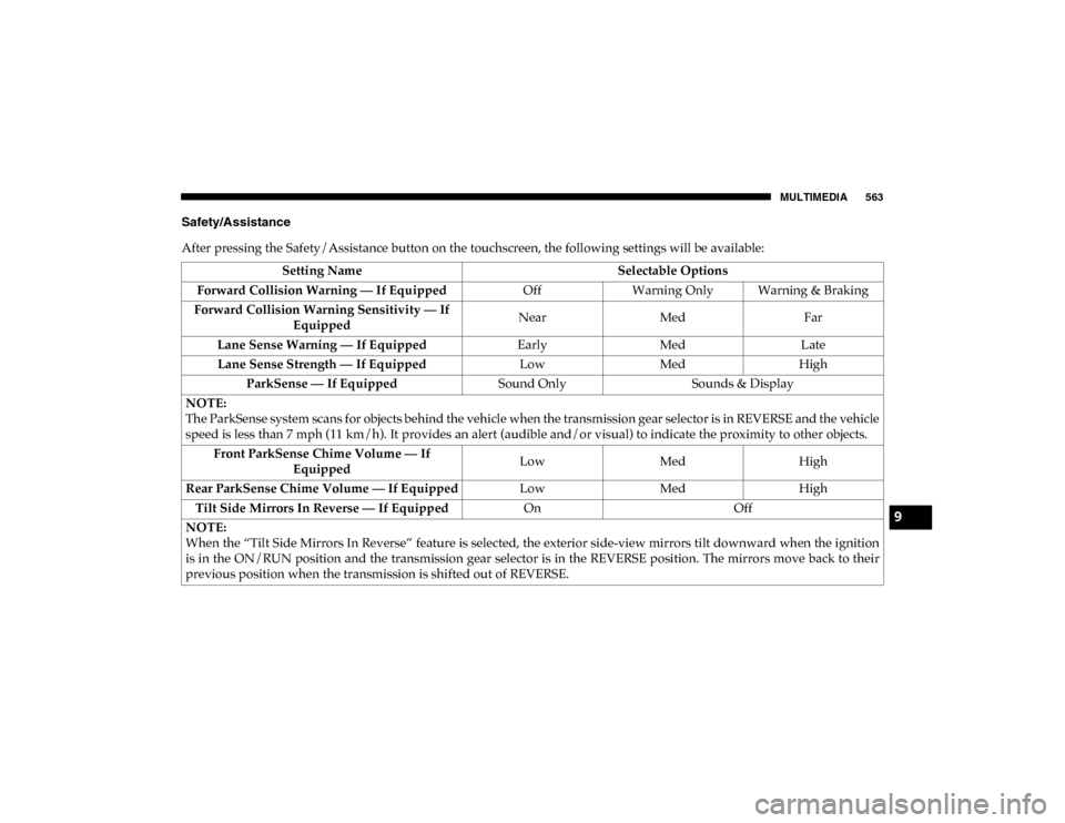
MULTIMEDIA 563
Safety/Assistance
After pressing the Safety/Assistance button on the touchscreen, the following settings will be available:Setting Name Selectable Options
Forward Collision Warning — If Equipped OffWarning Only Warning & Braking
Forward Collision Warning Sensitivity — If Equipped Near
Med Far
Lane Sense Warning — If Equipped EarlyMedLate
Lane Sense Strength — If Equipped LowMedHigh
ParkSense — If Equipped Sound OnlySounds & Display
NOTE:
The ParkSense system scans for objects behind the vehicle when the transmission gear selector is in REVERSE and the vehicle
speed is less than 7 mph (11 km/h). It provides an alert (audible and/or visual) to indicate the proximity to other objects. Front ParkSense Chime Volume — If Equipped Low
MedHigh
Rear ParkSense Chime Volume — If Equipped LowMedHigh
Tilt Side Mirrors In Reverse — If Equipped OnOff
NOTE:
When the “Tilt Side Mirrors In Reverse” feature is selected, the exterior side-view mirrors tilt downward when the ignition
is in the ON/RUN position and the transmission gear selector is in the REVERSE position. The mirrors move back to their
previous position when the transmission is shifted out of REVERSE.
9
2020_DT_1500_OM_US.book Page 563