RAM 1500 2023 Owners Manual
Manufacturer: RAM, Model Year: 2023, Model line: 1500, Model: RAM 1500 2023Pages: 416, PDF Size: 20.59 MB
Page 361 of 416
SERVICING AND MAINTENANCE359
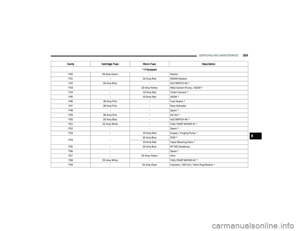
F4040 Amp Green –Starter
F41 –10 Amp RedIRCAM Heaters
F42 20 Amp Blue –AUX SWITCH #5 *
F43 –20 Amp Yellow MGU Coolant Pump / ADCM *
F44 –10 Amp RedTrailer Camera *
F45 –10 Amp RedADCM *
F46 30 Amp Pink –Fuel Heater *
F47 30 Amp Pink –Rear Defroster
F48 ––Spare *
F49 30 Amp Pink –Htr Ctrl *
F50 20 Amp Blue –AUX SWITCH #6 *
F51 25 Amp White –FUEL PUMP MOTOR #1 *
F52 ––Spare *
F53 –10 Amp RedSupply / Purging Pump *
F54 –15 Amp Blue
PCM *
10 Amp Red Vapor Blocking Valve *
F55 –15 Amp BlueRT HID Headlamp
F56 ––Spare *
F57 –20 Amp Yellow Horn
F58 25 Amp White –FUEL PUMP MOTOR #2 *
F59 –25 Amp ClearInjectors / IGN Coil / Glow Plug Module *
Cavity Cartridge Fuse Micro Fuse Description
* If Equipped
8
23_DT_OM_EN_USC_t.book Page 359
Page 362 of 416

360SERVICING AND MAINTENANCE
Internal Power Distribution Center
The Power Distribution Center is located under the driver’s
side instrument panel. This center contains cartridge
fuses, micro fuses, relays, and circuit breakers.
Fuse Cover Panel
See the following steps for accessing the interior fuses:
1. Locate and remove the two screws from the lower
portion of the fuse panel cover.
Fuse Panel Screw Locations
2. After removing the screws, gently pull both the left and right side of the fuse panel cover to release the
fastener clips.
Interior Fuse Box Location
3. Reverse the procedure to reinstall the fuse panel cover.
F60
–20 Amp Yellow ECM / PCM / ACT Short Running Valve / LTR Coolant Pump *
F61 –15 Amp BlueLT HID Headlamp
F62 60 Amp Blue
–Glow Plug *
40 Amp Green LTR Coolant Pump *
F63 20 Amp Blue –NOx Sensor *
F64 –10 Amp RedPM Sensor *
Cavity Cartridge Fuse Micro Fuse Description
* If Equipped
23_DT_OM_EN_USC_t.book Page 360
Page 363 of 416
SERVICING AND MAINTENANCE361
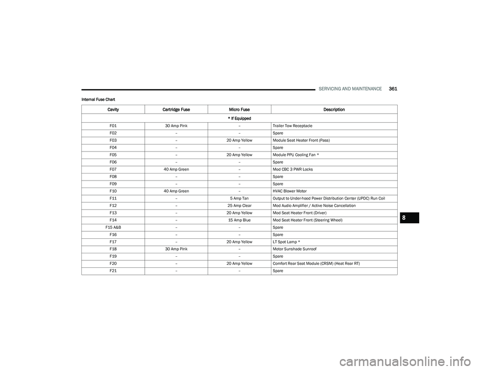
Internal Fuse Chart
CavityCartridge Fuse Micro Fuse Description
* If Equipped
F01 30 Amp Pink –Trailer Tow Receptacle
F02 ––Spare
F03 –20 Amp Yellow Module Seat Heater Front (Pass)
F04 ––Spare
F05 –20 Amp Yellow Module PPU Cooling Fan *
F06 ––Spare
F07 40 Amp Green –Mod CBC 3 PWR Locks
F08 ––Spare
F09 ––Spare
F10 40 Amp Green –HVAC Blower Motor
F11 –5 Amp TanOutput to Under-hood Power Distribution Center (UPDC) Run Coil
F12 –25 Amp ClearMod Audio Amplifier / Active Noise Cancellation
F13 –20 Amp Yellow Mod Seat Heater Front (Driver)
F14 –15 Amp BlueMod Seat Heater Front (Steering Wheel)
F15 A&B ––Spare
F16 ––Spare
F17 –20 Amp Yellow LT Spot Lamp *
F18 30 Amp Pink –Motor Sunshade Sunroof
F19 ––Spare
F20 –20 Amp Yellow Comfort Rear Seat Module (CRSM) (Heat Rear RT)
F21 ––Spare
8
23_DT_OM_EN_USC_t.book Page 361
Page 364 of 416
362SERVICING AND MAINTENANCE
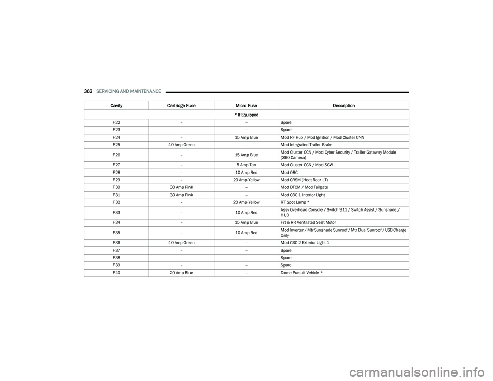
F22 ––Spare
F23 ––Spare
F24 –15 Amp BlueMod RF Hub / Mod Ignition / Mod Cluster CNN
F25 40 Amp Green –Mod Integrated Trailer Brake
F26 –15 Amp BlueMod Cluster CCN / Mod Cyber Security / Trailer Gateway Module
(360 Camera)
F27 –5 Amp TanMod Cluster CCN / Mod SGW
F28 –10 Amp RedMod ORC
F29 –20 Amp Yellow Mod CRSM (Heat Rear LT)
F30 30 Amp Pink –Mod DTCM / Mod Tailgate
F31 30 Amp Pink –Mod CBC 1 Interior Light
F32 –20 Amp Yellow RT Spot Lamp *
F33 –10 Amp RedAssy Overhead Console / Switch 911 / Switch Assist / Sunshade /
HUD
F34 –15 Amp BlueFrt & RR Ventilated Seat Motor
F35 –10 Amp RedMod Inverter / Mtr Sunshade Sunroof / Mtr Dual Sunroof / USB Charge
Only
F36 40 Amp Green –Mod CBC 2 Exterior Light 1
F37 ––Spare
F38 ––Spare
F39 ––Spare
F40 20 Amp Blue –Dome Pursuit Vehicle *
Cavity Cartridge Fuse Micro Fuse Description
* If Equipped
23_DT_OM_EN_USC_t.book Page 362
Page 365 of 416

SERVICING AND MAINTENANCE363
F41 A&B –15 Amp BlueLumbar Support & Pass SW / Steering Column Control Module / HVAC
Control Module / ICS Switch Bank / Upper Switch Bank
F42 A&B –10 Amp RedMod Transfer Case Switch Module (TCSM) / SBW / Electric Park Brake
SW / Module TPM Trailer / Module Gateway Can-C Trailer TPM / Seat
LT & RT Vent
F43 A&B –10 Amp RedPort Diagnostics / Front & Rear USB
F44 –20 Amp Yellow Radio / DCSD / Telematics Box Mod / Trailer Gateway Module (360)
F45 30 Amp Pink –Mod Door MUX Driver
F46 30 Amp Pink –Mod Door MUX Passenger
F47 ––Spare
F48A –10 Amp RedRear View Mirror / SW Window Passenger / Rear USB / Wireless
Charging Pad Mod
F49 –15 Amp BlueMod CVPM / SNSR Blind Spot / HDLP Adaptive Front Lighting Sensor
(AFLS)
F50A –10 Amp RedBattery PACK Control Mod (BPCM) *
F51 A&B ––Spare
F52 20 Amp Blue –Direct Battery Feed *
F53 –10 Amp RedTrailer Reverse Steering Control / Trailer Steering Control Knob
F54 A&B –20 Amp YellowPower Outlet Center Seat Battery Feed Position
Power Outlet Center Seat Ignition Feed Position
F55 25 Amp White –Upfitter *
F56 30 Amp Pink –Mod Network Interface *
F57 20 Amp Blue –Direct Battery Feed *
Cavity Cartridge Fuse Micro Fuse Description
* If Equipped
8
23_DT_OM_EN_USC_t.book Page 363
Page 366 of 416
364SERVICING AND MAINTENANCE
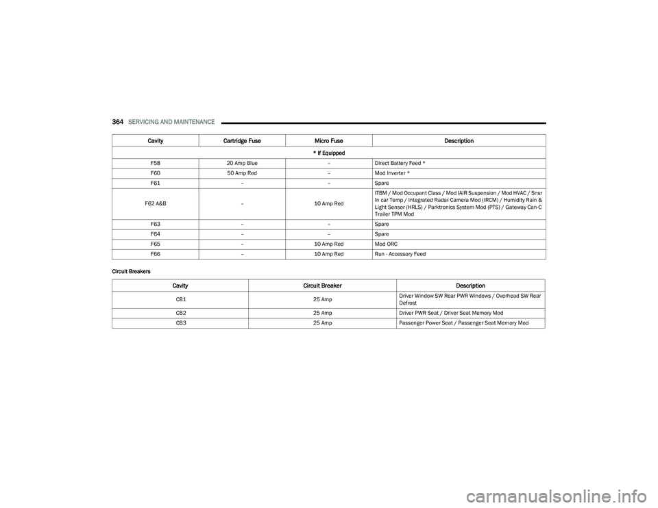
Circuit BreakersF58
20 Amp Blue –Direct Battery Feed *
F60 50 Amp Red –Mod Inverter *
F61 ––Spare
F62 A&B –10 Amp RedITBM / Mod Occupant Class / Mod IAIR Suspension / Mod HVAC / Snsr
In car Temp / Integrated Radar Camera Mod (IRCM) / Humidity Rain &
Light Sensor (HRLS) / Parktronics System Mod (PTS) / Gateway Can-C
Trailer TPM Mod
F63 ––Spare
F64 ––Spare
F65 –10 Amp RedMod ORC
F66 –10 Amp RedRun - Accessory Feed
Cavity Cartridge Fuse Micro Fuse Description
* If Equipped
Cavity Circuit Breaker Description
CB125 AmpDriver Window SW Rear PWR Windows / Overhead SW Rear
Defrost
CB2 25 AmpDriver PWR Seat / Driver Seat Memory Mod
CB3 25 AmpPassenger Power Seat / Passenger Seat Memory Mod
23_DT_OM_EN_USC_t.book Page 364
Page 367 of 416
SERVICING AND MAINTENANCE365
BULB REPLACEMENT
Replacement Bulbs, Names, And Part Numbers
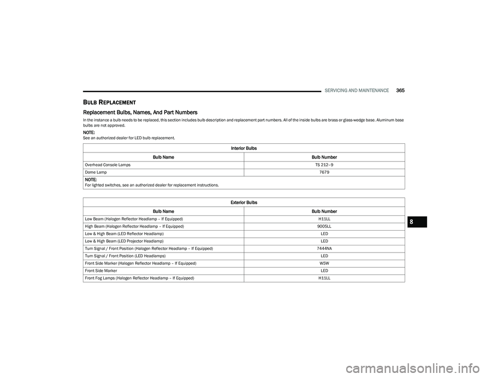
In the instance a bulb needs to be replaced, this section includes bulb description and replacement part numbers. All of the inside bulbs are brass or glass-wedge base. Aluminum base
bulbs are not approved.
NOTE:See an authorized dealer for LED bulb replacement.
Interior Bulbs
Bulb Name Bulb Number
Overhead Console Lamps TS 212–9
Dome Lamp 7679
NOTE:For lighted switches, see an authorized dealer for replacement instructions.
Exterior Bulbs
Bulb Name Bulb Number
Low Beam (Halogen Reflector Headlamp – If Equipped) H11LL
High Beam (Halogen Reflector Headlamp – If Equipped) 9005LL
Low & High Beam (LED Reflector Headlamp) LED
Low & High Beam (LED Projector Headlamp) LED
Turn Signal / Front Position (Halogen Reflector Headlamp – If Equipped) 7444NA
Turn Signal / Front Position (LED Headlamps) LED
Front Side Marker (Halogen Reflector Headlamp – If Equipped) W5W
Front Side Marker LED
Front Fog Lamps (Halogen Reflector Headlamp – If Equipped) H11LL8
23_DT_OM_EN_USC_t.book Page 365
Page 368 of 416
366SERVICING AND MAINTENANCE
Replacing Exterior Bulbs
BASE QUAD: LOW BEAM HEADLAMP, HIGH
BEAM HEADLAMP, FRONT PARK AND TURN —
IF EQUIPPED
Low Beam
See the following steps to replace:
1. Open the hood.
2. Disconnect and isolate the negative battery cable.
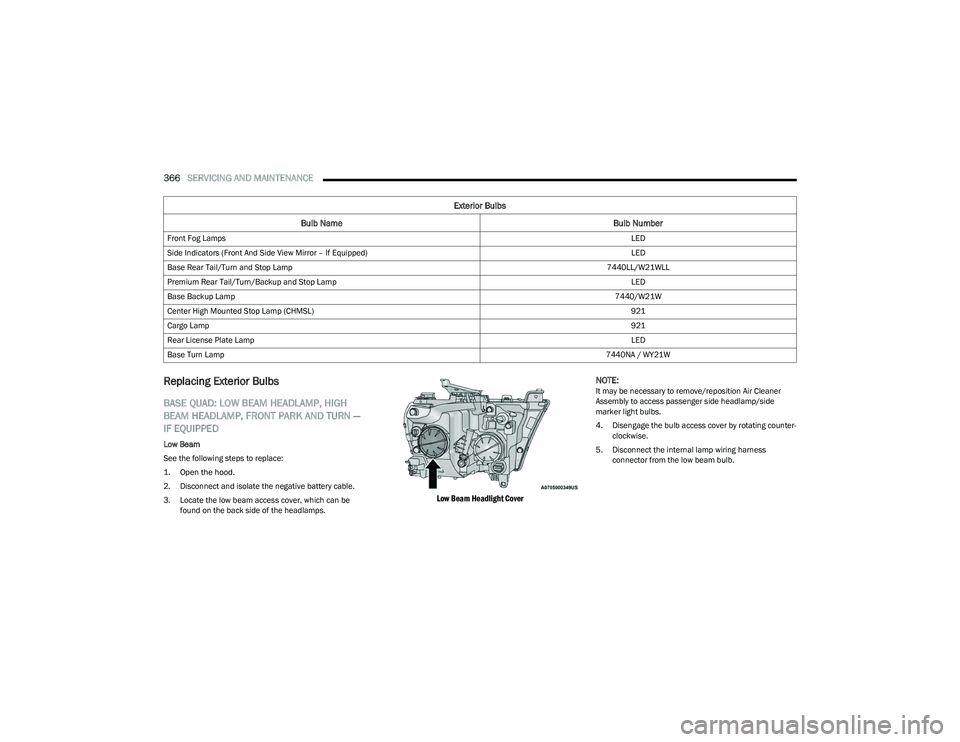
3. Locate the low beam access cover, which can be
found on the back side of the headlamps.
Low Beam Headlight Cover
NOTE:
It may be necessary to remove/reposition Air Cleaner
Assembly to access passenger side headlamp/side
marker light bulbs.
4. Disengage the bulb access cover by rotating counter
-
clockwise.
5. Disconnect the internal lamp wiring harness connector from the low beam bulb.
Front Fog Lamps
LED
Side Indicators (Front And Side View Mirror – If Equipped) LED
Base Rear Tail/Turn and Stop Lamp 7440LL/W21WLL
Premium Rear Tail/Turn/Backup and Stop Lamp LED
Base Backup Lamp 7440/W21W
Center High Mounted Stop Lamp (CHMSL) 921
Cargo Lamp 921
Rear License Plate Lamp LED
Base Turn Lamp 7440NA / WY21W
Exterior Bulbs
Bulb Name Bulb Number
23_DT_OM_EN_USC_t.book Page 366
Page 369 of 416
SERVICING AND MAINTENANCE367
6. Rotate the bulb counterclockwise a quarter turn to
unlock the bulb from the lamp.
7. Pull the bulb straight out from the housing.
8. Reverse the procedure for installation of new bulb and covers.
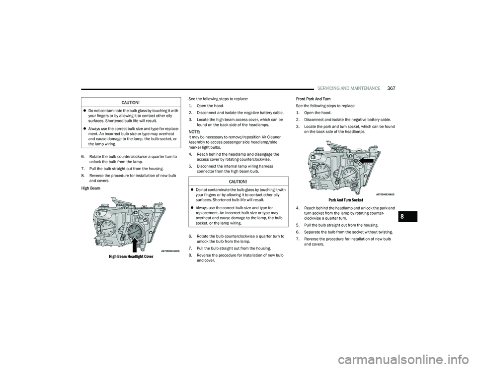
High Beam
High Beam Headlight Cover
See the following steps to replace:
1. Open the hood.
2. Disconnect and isolate the negative battery cable.
3. Locate the high beam access cover, which can be found on the back side of the headlamps.
NOTE:It may be necessary to remove/reposition Air Cleaner
Assembly to access passenger side headlamp/side
marker light bulbs.
4. Reach behind the headlamp and disengage the access cover by rotating counterclockwise.
5. Disconnect the internal lamp wiring harness connector from the high beam bulb.
6. Rotate the bulb counterclockwise a quarter turn to unlock the bulb from the lamp.
7. Pull the bulb straight out from the housing.
8. Reverse the procedure for installation of new bulb and cover. Front Park And Turn
See the following steps to replace:
1. Open the hood.
2. Disconnect and isolate the negative battery cable.
3. Locate the park and turn socket, which can be found
on the back side of the headlamps.
Park And Turn Socket
4. Reach behind the headlamp and unlock the park and turn socket from the lamp by rotating counter -
clockwise a quarter turn.
5. Pull the bulb straight out from the housing.
6. Separate the bulb from the socket without twisting.
7. Reverse the procedure for installation of new bulb and covers.
CAUTION!
Do not contaminate the bulb glass by touching it with
your fingers or by allowing it to contact other oily
surfaces. Shortened bulb life will result.
Always use the correct bulb size and type for replace -
ment. An incorrect bulb size or type may overheat
and cause damage to the lamp, the bulb socket, or
the lamp wiring.
CAUTION!
Do not contaminate the bulb glass by touching it with
your fingers or by allowing it to contact other oily
surfaces. Shortened bulb life will result.
Always use the correct bulb size and type for
replacement. An incorrect bulb size or type may
overheat and cause damage to the lamp, the bulb
socket, or the lamp wiring.
8
23_DT_OM_EN_USC_t.book Page 367
Page 370 of 416
368SERVICING AND MAINTENANCE
Side Marker Lamp
See the following steps to replace:
1. Open the hood.
2. Disconnect and isolate the negative battery cable.
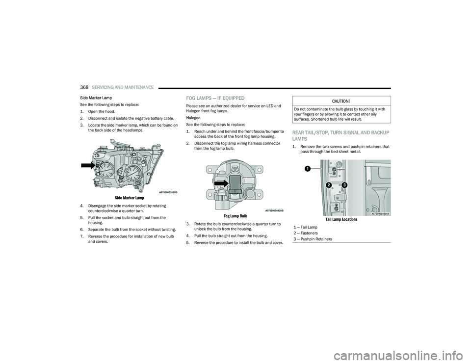
3. Locate the side marker lamp, which can be found on
the back side of the headlamps.
Side Marker Lamp
4. Disengage the side marker socket by rotating counterclockwise a quarter turn.
5. Pull the socket and bulb straight out from the housing.
6. Separate the bulb from the socket without twisting.
7. Reverse the procedure for installation of new bulb and covers.
FOG LAMPS — IF EQUIPPED
Please see an authorized dealer for service on LED and
Halogen front fog lamps.
Halogen
See the following steps to replace:
1. Reach under and behind the front fascia/bumper to access the back of the front fog lamp housing.
2. Disconnect the fog lamp wiring harness connector from the fog lamp bulb.
Fog Lamp Bulb
3. Rotate the bulb counterclockwise a quarter turn to unlock the bulb from the housing.
4. Pull the bulb straight out from the housing.
5. Reverse the procedure to install the bulb and cover.
REAR TAIL/STOP, TURN SIGNAL AND BACKUP
LAMPS
1. Remove the two screws and pushpin retainers that pass through the bed sheet metal.
Tail Lamp Locations
CAUTION!
Do not contaminate the bulb glass by touching it with
your fingers or by allowing it to contact other oily
surfaces. Shortened bulb life will result.
1 — Tail Lamp
2 — Fasteners
3 — Pushpin Retainers
23_DT_OM_EN_USC_t.book Page 368