ignition Ram 3500 2020 Owner's Manual
[x] Cancel search | Manufacturer: RAM, Model Year: 2020, Model line: 3500, Model: Ram 3500 2020Pages: 568
Page 312 of 568
310STARTING AND OPERATING
When the vehicle is shifted out of REVERSE
(with Camera delay turned on), the rear Camera
image will be displayed for up to 10 seconds
after shifting to another gear, unless the vehicle
speed exceeds 8 mph (13 km/h), the
transmission is shifted into PARK, the ignition is
placed in the OFF position, or the touchscreen
button “X” to disable display of the Rear View
Camera image is pressed.
Whenever the Rear View Camera image is
activated through the "Backup Camera" button
in the "Controls" menu, and the vehicle speed is
greater than, or equal to, 8 mph (13 km/h), a
display timer for the image is initiated. The
image will continue to be displayed until the
display timer exceeds 10 seconds.
NOTE:
If the vehicle speed remains below 8 mph
(13 km/h), the Rear View Camera image will
be displayed continuously until deactivated
via the touchscreen button "X", the transmis -
sion is shifted into PARK, or the ignition is
placed in the OFF position.
The touchscreen button "X" to disable display
of the camera image is made available ONLY
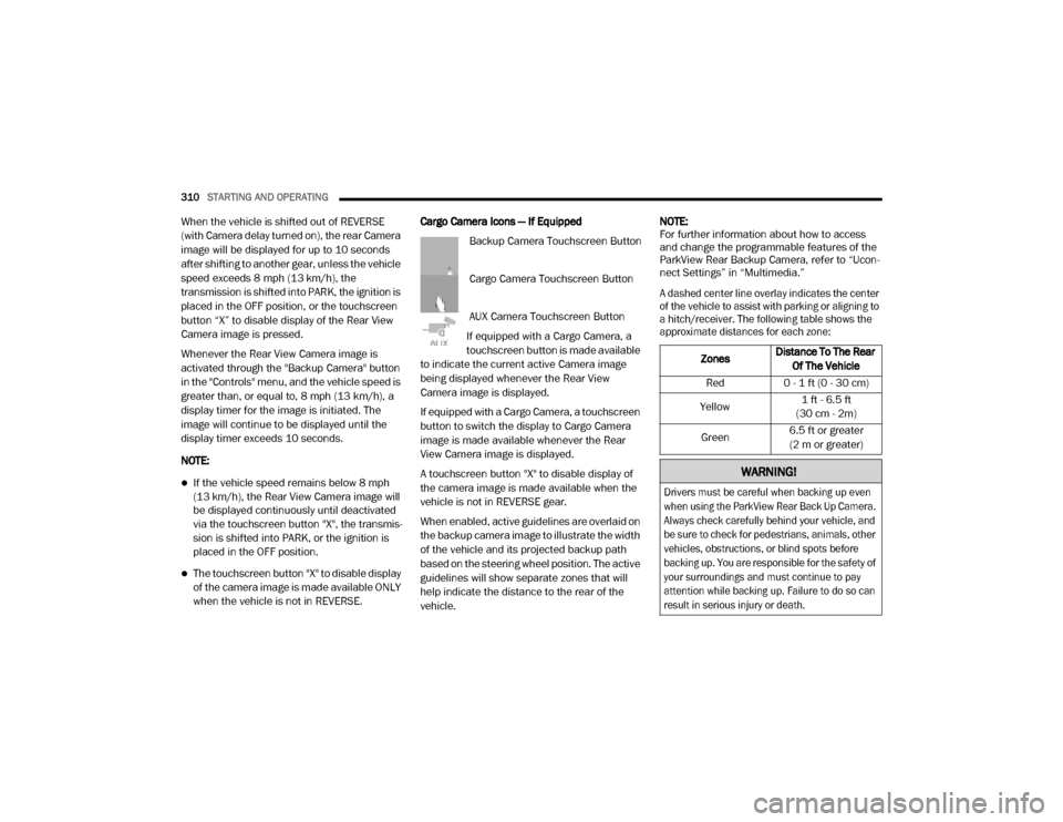
when the vehicle is not in REVERSE. Cargo Camera Icons — If Equipped
Backup Camera Touchscreen Button
Cargo Camera Touchscreen Button
AUX Camera Touchscreen Button
If equipped with a Cargo Camera, a
touchscreen button is made available
to indicate the current active Camera image
being displayed whenever the Rear View
Camera image is displayed.
If equipped with a Cargo Camera, a touchscreen
button to switch the display to Cargo Camera
image is made available whenever the Rear
View Camera image is displayed.
A touchscreen button "X" to disable display of
the camera image is made available when the
vehicle is not in REVERSE gear.
When enabled, active guidelines are overlaid on
the backup camera image to illustrate the width
of the vehicle and its projected backup path
based on the steering wheel position. The active
guidelines will show separate zones that will
help indicate the distance to the rear of the
vehicle. NOTE:
For further information about how to access
and change the programmable features of the
ParkView Rear Backup Camera, refer to “Ucon
-
nect Settings” in “Multimedia.”
A dashed center line overlay indicates the center
of the vehicle to assist with parking or aligning to
a hitch/receiver. The following table shows the
approximate distances for each zone:
Zones Distance To The Rear
Of The Vehicle
Red 0 - 1 ft (0 - 30 cm)
Yellow 1 ft - 6.5 ft
(30 cm - 2m)
Green 6.5 ft or greater
(2 m or greater)
WARNING!
Drivers must be careful when backing up even
when using the ParkView Rear Back Up Camera.
Always check carefully behind your vehicle, and
be sure to check for pedestrians, animals, other
vehicles, obstructions, or blind spots before
backing up. You are responsible for the safety of
your surroundings and must continue to pay
attention while backing up. Failure to do so can
result in serious injury or death.
20_DJD2_OM_EN_USC_t.book Page 310
Page 314 of 568
312STARTING AND OPERATING
Deactivation
The AUX Camera is deactivated by pressing the
“X” in the upper right corner of the touchscreen.
This will return the display back to the
previously displayed screen.
NOTE:
If the AUX button is pressed and no AUX
Camera is connected, the touchscreen will
display a blue screen along with the message
“Camera System Unavailable.” The screen
can be exited out by pressing the “X” in the
upper right hand corner. This will return the
display back to the previously displayed
screen.
Zoom View is not available with the AUX
Camera feature.
The display will always default to the Trailer
Camera display (AUX 1).
SURROUND VIEW CAMERA SYSTEM — IF
EQUIPPED
Your vehicle may be equipped with the
Surround View Camera system that allows you
to see an on-screen image of the surroundings
and Top View of your vehicle whenever the gear
selector is put into REVERSE or manually
activated via the Uconnect system. The Top
View of the vehicle will show which doors are
open. The image will be displayed on the
touchscreen display along with a caution note
“Check Entire Surroundings” across the top of
the screen. After five seconds, this note will
disappear. The Surround View Camera system
is comprised of four sequential cameras
located in the front grille, rear tailgate and side
mirrors.
NOTE:
The Surround View Camera system has
programmable settings that may be selected
through the Uconnect System. Refer to “Ucon -
nect Settings” in “Multimedia” for further infor -
mation. When the vehicle is shifted into REVERSE, the
Rear View and Top View is the default view of
the system (Automatic Activation).
When the vehicle is shifted out of REVERSE (with
camera delay turned on), the Rear View will
continue to be displayed for up to 10 seconds,
unless the vehicle speed exceeds 8 mph
(13 km/h), the vehicle is shifted into PARK or the
ignition is placed in the OFF position. There is a
touchscreen button “X” to disable the display of
the camera image.
When the vehicle is shifted out of REVERSE
(with camera delay turned off), the Surround
View system is exited and the last known screen
appears again.
While the Rear View is displayed and guidelines
are enabled, active guidelines are overlaid on
the image to illustrate the width of the vehicle,
including the side view mirrors and its projected
backup path based on the steering wheel
position.
Different colored zones indicate the distance to
the rear of the vehicle.
20_DJD2_OM_EN_USC_t.book Page 312
Page 317 of 568
STARTING AND OPERATING315
Deactivation
The system is deactivated in the following
conditions if it was activated automatically:
When the vehicle is shifted out of REVERSE
(with camera delay turned on), the camera
image will continue to be displayed for up to
10 seconds, unless the vehicle speed
exceeds 8 mph (13 km/h), the vehicle is
shifted into PARK or the ignition is placed in
the OFF position. There is a touch screen
button “X” to disable the display of the
camera image.
When the vehicle is shifted out of REVERSE
(with camera delay turned off), the Surround
View Camera mode is exited and the last
known screen appears again.
The system is deactivated in the following
conditions if it was activated manually from the
Uconnect controls menu via the Surround View button, Backup Camera button, Cargo Camera
button or Forward Facing Camera button:
The "X" button on the display is pressed
Vehicle is shifted into PARK
Ignition is placed in the OFF position
Vehicle speed is over 8 mph (13 km/h) for
10 seconds
NOTE:
If the Surround View Camera, Cargo Camera,
Backup Camera, or Forward Facing Camera is
activated manually, and the vehicle is shifted
into REVERSE, deactivation methods for auto -
matic activation are assumed.
The camera delay system is turned off manually
through the Uconnect Settings menu. Refer to
“Uconnect Settings” in “Multimedia” for further
information.
NOTE:
If snow, ice, mud, or any foreign substance
builds up on the camera lenses, clean the
lenses, rinse with water, and dry with a soft
cloth. Do not cover the lenses.
If a malfunction with the system has
occurred, see an authorized dealer. Cargo Camera With Dynamic Centerline — If
Equipped
The Dynamic Centerline feature provides an
overlay on the Cargo Camera display screen
that aligns to the center of the pickup box to aid
in hooking up a fifth wheel camper or
gooseneck trailer. The centerline auto aligns to
the center of the pickup box, and can also be
manually adjusted. The centerline will adjust in
response to steering angle inputs, and will not
obstruct the gooseneck receiver or an
approaching trailer gooseneck in the camera
feed.
Activation
The Dynamic Centerline feature can be
activated through the Uconnect settings by
pressing the Cargo Camera soft button,
followed by the “Dynamic Centerline” soft
button on the touchscreen.
If the Dynamic Centerline feature is turned on,
the overlay will display anytime the Cargo
Camera image is displayed.
5
20_DJD2_OM_EN_USC_t.book Page 315
Page 319 of 568
STARTING AND OPERATING317
(Continued)
Deactivation
The Forward Facing Camera is deactivated in
the following conditions:
The vehicle is not in 4WD Low and the vehicle
speed exceeds 8 mph (13 km/h) for
10 seconds.
The “X” button on the display is pressed.
Vehicle is shifted into PARK.
Ignition is placed in the OFF position.
NOTE:
If the vehicle is in 4WD Low, the Forward Facing
Camera image will be displayed until the “X”
button is pressed or the ignition is placed in the
OFF position. If the vehicle goes out of 4WD
Low, then the regular deactivation conditions
listed above are applied.
Trailer Reverse Guidance — If Equipped
The Trailer Reverse Guidance feature assists
the driver in backing up a trailer by providing
adjustable camera views of the trailer and
surrounding area. The cameras are mounted on
the side mirrors and the images will be displayed side-by-side on the touchscreen. Left
and right camera images are swapped and
mirrored on the touchscreen to show the
equivalent area behind the vehicle as though
the driver is using the side mirrors.
Activation
The Trailer Reverse Guidance feature can be
activated by pressing the Trailer Reverse
Guidance button on the Backup/Cargo Camera
Display.
Deactivation
When the vehicle is shifted out of REVERSE
(with camera delay turned on), the camera
image will continue to be displayed for up to
10 seconds, unless the vehicle speed exceeds
8 mph (13 km/h), the vehicle is shifted into
PARK or the ignition is placed in the OFF
position. There is a touchscreen button “X” to
disable the display of the camera image.
If Trailer Reverse Guidance is selected through
manually activated Surround View, Backup
Camera, or Cargo Camera, the below
deactivation conditions apply:
The “X” button on the display is pressed
The vehicle is shifted into PARK
The ignition is placed in the OFF position
The vehicle speed is over 8 mph (13 km/h)
for 10 seconds
WARNING!
Drivers must be careful when backing up
even when using the Surround View Camera.
Always check carefully behind your vehicle,
and be sure to check for pedestrians,
animals, other vehicles, obstructions, or blind
spots before backing up. You are responsible
for the safety of your surroundings and must
continue to pay attention while backing up.
Failure to do so can result in serious injury or
death.
CAUTION!
To avoid vehicle damage, Surround View
should only be used as a parking aid. The
Surround View camera is unable to view
every obstacle or object in your drive path.
5
20_DJD2_OM_EN_USC_t.book Page 317
Page 321 of 568
STARTING AND OPERATING319
(Continued)
ENGINE RUNAWAY — DIESEL ENGINE
Diesel engine runaway is a rare condition
affecting diesel engines, where the engine
consumes its own lubrication oil and runs at
higher and higher RPM until it overspeeds to a
point where it destroys itself due to either
mechanical failure or engine seizure through
lack of lubrication.
REFUELING THE VEHICLE — GAS ENGINE
The fuel filler cap (gas cap) is located behind the
fuel filler door, on the left side of the vehicle.
Open the fuel door and remove the fuel filler cap
by turning it counter-clockwise.
Fuel Filler Cap
NOTE:
When removing the fuel filler cap, lay the cap
tether in the hook, located on the fuel filler door.
NOTE:
When the fuel nozzle “clicks” or shuts off, the
fuel tank is full.
WARNING!
In case of engine runaway due to flammable
fumes from fuel spills or turbocharger oil
leaks being sucked into the engine, do the
following to help avoid personal injury and/or
vehicle damage:
1. Turn the ignition switch to the OFF position.
2. Using a CO2 or dry chemical type fire
extinguisher, direct the spray from the fire
extinguisher into the grille on the driver side
so that the spray enters the engine air intake.
The inlet for the engine air intake is located
behind the drivers side headlamp and
receives air through the grille.
WARNING!
Never have any smoking materials lit in or
near the vehicle when the gas cap is
removed or the tank is being filled.
Never add fuel to the vehicle when the
engine is running.
A fire may result if gasoline is pumped into
a portable container that is inside of a
vehicle. You could be burned. Always place
gas containers on the ground while filling.
CAUTION!
Damage to the fuel system or emissions
control system could result from using an
improper fuel tank filler tube cap.
A poorly fitting fuel filler cap could let impu-
rities into the fuel system.
A poorly fitting fuel filler cap may cause the
“Malfunction Indicator Light (MIL)” to turn
on.
To avoid fuel spillage and overfilling, do not
“top off” the fuel tank after filling. When the
fuel nozzle “clicks” or shuts off, the fuel
tank is full.
WARNING! (Continued)
5
20_DJD2_OM_EN_USC_t.book Page 319
Page 322 of 568
320STARTING AND OPERATING
Tighten the gas cap until you hear a “clicking”
sound. This is an indication that the gas cap
is tightened properly. The MIL in the instru -
ment cluster may turn on if the gas cap is not
secured properly. Make sure that the gas cap
is tightened each time the vehicle is refueled.
LOOSE FUEL FILLER CAP MESSAGE
If the vehicle diagnostic system
determines that the fuel filler cap is
loose, improperly installed, or
damaged, a loose gASCAP indicator
will display in the instrument cluster telltale
display area. Refer to “Instrument Cluster Display” in “Getting To Know Your Instrument
Panel” for further information. Tighten the fuel
filler cap properly and push the RIGHT button to
turn off the message. If the problem continues,
the message will appear the next time the
vehicle is started.
REFUELING THE VEHICLE — DIESEL ENGINE
1. Open the fuel filler door.
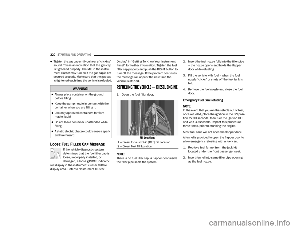
Fill Locations
NOTE:
There is no fuel filler cap. A flapper door inside
the filler pipe seals the system. 2. Insert the fuel nozzle fully into the filler pipe
– the nozzle opens and holds the flapper
door while refueling.
3. Fill the vehicle with fuel – when the fuel nozzle “clicks” or shuts off the fuel tank is
full.
4. Remove the fuel nozzle and close the fuel door.
Emergency Fuel Can Refueling
NOTE:
In the event that you run the vehicle out of fuel,
once refueled, place the ignition in the ON posi -
tion for 30 seconds, then turn the ignition OFF
and wait 30 seconds. Repeat this procedure
three times, prior to cranking the engine.
Most fuel cans will not open the flapper door.
A funnel is provided to open the flapper door to
allow emergency refueling with a fuel can.
1. Retrieve fuel funnel from the jack kit located under the front passenger seat.
2. Insert funnel into same filler pipe opening as the fuel nozzle.
WARNING!
Always place container on the ground
before filling.
Keep the pump nozzle in contact with the
container when you are filling it.
Use only approved containers for flam -
mable liquid.
Do not leave container unattended while
filling.
A static electric charge could cause a spark
and fire hazard.
1 — Diesel Exhaust Fluid (DEF) Fill Location
2 — Diesel Fuel Fill Location
20_DJD2_OM_EN_USC_t.book Page 320
Page 334 of 568

332STARTING AND OPERATING
Integrated Trailer Brake Module — If
Equipped
Your vehicle may have an Integrated Trailer
Brake Module (ITBM) for Electric and Electric
Over Hydraulic (EOH) trailer brakes.
NOTE:
This module has been designed and verified
with electric trailer brakes and new electric over
hydraulic systems. Some previous EOH systems
may not be compatible with ITBM.
Integrated Trailer Brake Module (ITBM)
The user interface consists of the following:
Manual Brake Control Lever
Slide the manual brake control lever to the left
to activate power to the trailer's electric brakes
independent of the tow vehicle's brakes. If the
manual brake control lever is activated while
the brake is also applied, the greater of the two
inputs determines the power sent to the trailer
brakes.
The trailer and the vehicle’s stop lamps will
come on when braking normally with the vehicle
brake pedal. Only the trailer stop lamps will
come on when the manual brake control lever is
applied.
Trailer Brake Status Indicator Light
This light indicates the trailer electrical
connection status.
If no electrical connection is detected after the
ignition is turned on, pushing the GAIN
adjustment button or sliding the manual brake
control lever will display the GAIN setting for
10 seconds and the “Trailer Brake Status
Indicator Light” will not be displayed.
WARNING!
Do not connect trailer brakes to your
vehicle's hydraulic brake lines. It can over
-
load your brake system and cause it to fail.
You might not have brakes when you need
them and could have an accident.
Towing any trailer will increase your stop -
ping distance. When towing, you should
allow for additional space between your
vehicle and the vehicle in front of you.
Failure to do so could result in an accident.
CAUTION!
If the trailer weighs more than 1,000 lbs
(453 kg) loaded, it should have its own
brakes and they should be of adequate
capacity. Failure to do this could lead to
accelerated brake lining wear, higher brake
pedal effort, and longer stopping distances.
1 — GAIN Adjustment Button
2 — GAIN Adjustment Button
3 — Manual Brake Control Lever
20_DJD2_OM_EN_USC_t.book Page 332
Page 342 of 568

340STARTING AND OPERATING
(Continued)
2. Drive the rear wheels onto the tow dolly.
3. Firmly apply the parking brake. Place automatic transmission in PARK.
4. Properly secure the rear wheels to the dolly, following the dolly manufacturer's
instructions.
5. Turn the ignition OFF and remove the key fob.
6. Install a suitable clamping device, designed for towing, to secure the front wheels in the
straight position.RECREATIONAL TOWING —
F
OUR-WHEEL DRIVE MODELS
NOTE:
Both the manual shift and electronic shift
transfer cases must be shifted into NEUTRAL
(N) for recreational towing. Automatic transmis -
sions must be shifted into PARK for recreational
towing. Refer to the following for the proper
transfer case NEUTRAL (N) shifting procedure
for your vehicle.
CAUTION!
Towing with the rear wheels on the ground
will cause severe transmission damage.
Damage from improper towing is not
covered under the New Vehicle Limited
Warranty.
Do not disconnect the driveshaft because
fluid may leak from the transmission,
causing damage to internal parts.
CAUTION!
DO NOT dolly tow any 4WD vehicle. Towing
with only one set of wheels on the ground
(front or rear) will cause severe transmis -
sion and/or transfer case damage. Tow
with all four wheels either ON the ground, or
OFF the ground (using a vehicle trailer).
Tow only in the forward direction. Towing
this vehicle backwards can cause severe
damage to the transfer case.
Before recreational towing, the transfer
case must be in NEUTRAL. To be certain the
transfer case is fully in NEUTRAL, perform
the procedure outlined under “Shifting Into
NEUTRAL”. Internal transmission damage
will result, if the transfer case is not in
NEUTRAL during towing.
The transmission must be placed in PARK
for recreational towing.
Towing this vehicle in violation of the above
requirements can cause severe transmis -
sion and/or transfer case damage.
Damage from improper towing is not
covered under the New Vehicle Limited
Warranty.
Do not disconnect the rear driveshaft
because fluid will leak from the transfer
case, causing damage to internal parts.
Do not use a bumper-mounted clamp-on
tow bar on your vehicle. The bumper face
bar will be damaged.
CAUTION! (Continued)
20_DJD2_OM_EN_USC_t.book Page 340
Page 343 of 568

STARTING AND OPERATING341
Shifting Into (N) NEUTRAL
Use the following procedure to prepare your
vehicle for recreational towing.
1. Bring the vehicle to a complete stop on
level ground, with the engine running.
Firmly apply the parking brake.
2. Shift the transmission to NEUTRAL. NOTE:
If vehicle is equipped with air suspension,
ensure the vehicle is set to Normal Ride Height.
3. Press and hold the brake pedal.
4. Shift the transfer case into N (Neutral):
With manual shift transfer case, shift the
transfer case lever into N (Neutral)
With electronic shift transfer case, push
and hold the transfer case N (Neutral)
button. Some models have a small,
recessed “N” button (at the center of the
transfer case switches) that must be
pushed using a ballpoint pen or similar
object. Other models have a rectangular
N (Neutral) switch, below the rotary
transfer case control knob. The N
(Neutral) indicator light will blink while
the shift is in progress. The light will stop
blinking (stay on solid) when the shift to N
(Neutral) is complete. After the shift is
completed and the N (Neutral) light stays
on, release the N (Neutral) button.
5. Release the parking brake.
6. Shift the transmission into REVERSE. 7. Release the brake pedal for five seconds
and ensure that there is no vehicle
movement.
8. Repeat steps 6 and 7 with automatic transmission in DRIVE.
9. Shift the transmission to NEUTRAL. Firmly apply the parking brake. Turn off the engine.
For vehicles with Keyless Enter-N-Go, push
and hold the ENGINE START/STOP button
until the engine shuts off.
10. Shift the transmission into PARK. On 8-speed transmissions the shifter will
automatically select PARK when the engine
is turned off.
11. Turn the ignition to the OFF mode, then cycle the ignition to the RUN mode and back
to the OFF mode. Remove the key fob from
the ignition.
12. Attach the vehicle to the tow vehicle using a suitable tow bar.
13. Release the parking brake.
WARNING!
You or others could be injured or killed if you
leave the vehicle unattended with the transfer
case in the NEUTRAL (N) position without first
fully engaging the parking brake. The transfer
case NEUTRAL (N) position disengages both
the front and rear driveshafts from the
powertrain, and will allow the vehicle to roll,
even if the automatic transmission is in PARK.
The parking brake should always be applied
when the driver is not in the vehicle.
CAUTION!
It is necessary to follow these steps to be
certain that the transfer case is fully in
NEUTRAL (N) before recreational towing to
prevent damage to internal parts.
5
20_DJD2_OM_EN_USC_t.book Page 341
Page 344 of 568

342STARTING AND OPERATING
NOTE:
With electronic shift transfer case:
Steps 2 through 3 are requirements that
must be met before pushing the N (Neutral)
button, and must continue to be met until the
shift has been completed. If any of these
requirements are not met before pushing the
N (Neutral) button or are no longer met
during the shift, the N (Neutral) indicator light
will flash continuously until all requirements
are met or until the N (Neutral) button is
released.
The ignition must be in the ON/RUN mode for
a shift to take place and for the position indi -
cator lights to be operable. If the ignition is
not in the ON/RUN mode, the shift will not
take place and no position indicator lights will
be on or flashing.
A flashing N (Neutral) position indicator light
indicates that shift requirements have not
been met.
If the vehicle is equipped with air suspension,
the engine should be started and left running
for a minimum of 60 seconds (with all the
doors closed) at least once every 24 hours. This process allows the air suspension to
adjust the vehicle’s ride height to compen
-
sate for temperature effects.
Shifting Out Of (N) NEUTRAL
Use the following procedure to prepare your
vehicle for normal usage:
1. Bring the vehicle to a complete stop,
leaving it connected to the tow vehicle.
2. Firmly apply the parking brake.
3. Press and hold the brake pedal.
4. Start the engine. Shift the transmission into NEUTRAL.
With manual shift transfer case, shift the
transfer case lever to the desired posi -
tion.
With electronic shift transfer case with
rotary selector switch, push and hold the
transfer case N (Neutral) button until the
N (Neutral) indicator light turns off. After
the N (Neutral) indicator light turns off,
release the N (Neutral) button. After the
N (Neutral) button has been released, the
transfer case will shift to the position indi -
cated by the selector switch.
With electronic shift transfer case with
push-button selector switch, push and
hold the switch for the desired transfer
case position, until the N (Neutral) indi -
cator light turns off and the desired posi -
tion indicator light turns on.
NOTE:
When shifting out of transfer case N (Neutral),
turning the engine OFF is not required, but may
be helpful to avoid gear clash. With the 8-speed
automatic transmission, the engine must
remain running, since turning the engine OFF
will shift the transmission to PARK (and the
transmission must be in NEUTRAL for the
transfer case to shift out of NEUTRAL).
5. Turn the engine off. Shift automatic transmission into PARK. On 8-speed
transmissions the shifter will automatically
select PARK when the engine is turned off.
6. Release the brake pedal.
7. Disconnect vehicle from the tow vehicle.
8. Start the engine.
9. Press and hold the brake pedal.
10. Release the parking brake.
20_DJD2_OM_EN_USC_t.book Page 342