ECO mode Ram 4500 Chassis Cab 2018 Owner's Manual
[x] Cancel search | Manufacturer: RAM, Model Year: 2018, Model line: 4500 Chassis Cab, Model: Ram 4500 Chassis Cab 2018Pages: 298, PDF Size: 5.88 MB
Page 45 of 298
• If your air conditioning performance seemslower than expected, check the front of the
A/C condenser (located in front of the ra-
diator), for an accumulation of dirt or in-
sects. Clean with a gentle water spray from
the front of the radiator and through the
condenser.
MAX A/C
MAX A/C sets the control for maximum cool-
ing performance.
Press and release to toggle between MAX A/C
and the prior settings. The button illuminates
when MAX A/C is on.
In MAX A/C, the blower level and mode posi-
tion can be adjusted to desired user settings.
Pressing other settings will cause the MAX
A/C operation to switch to the selected set-
ting and MAX A/C to exit.
Recirculation
When outside air contains smoke, odors, or
high humidity, or if rapid cooling is desired,
you may wish to recirculate interior air by
pressing the Recirculation control button.
The Recirculation indicator will illuminate when this button is selected. Press the button
a second time to turn off the Recirculation
mode and allow outside air into the vehicle.
NOTE:
In cold weather, use of Recirculation mode
may lead to excessive window fogging. The
Recirculation feature may be unavailable
(button on the touchscreen greyed out) if
conditions exist that could create fogging on
the inside of the windshield.
Automatic Temperature Control
(ATC) — If Equipped
Automatic Operation
1. Push the AUTO button on the faceplate,
or the AUTO button on the touchscreen on
the Automatic Temperature Control (ATC)
Panel.
2. Next, adjust the temperature you would like the system to maintain by adjusting
the driver and passenger temperature
control buttons. Once the desired tem-
perature is displayed, the system will
achieve and automatically maintain that
comfort level. 3. When the system is set up for your comfort
level, it is not necessary to change the
settings. You will experience the greatest
efficiency by simply allowing the system
to function automatically.
NOTE:
• It is not necessary to move the temperature settings for cold or hot vehicles. The system
automatically adjusts the temperature,
mode, and blower speed to provide comfort
as quickly as possible.
• The temperature can be displayed in U.S. or Metric units by selecting the US/Metric
customer-programmable feature. Refer to
the “Uconnect Settings” in “Multimedia”
in your Owner’s Manual at www.mopar.com/
en-us/care/owners-manual.html (U.S.
Residents) or www.owners.mopar.ca
(Canadian Residents) for further information.
To provide you with maximum comfort in the
Automatic mode during cold start-ups, the
blower fan will remain on low until the engine
warms up. The blower will increase in speed
and transition into Auto mode.
43
Page 46 of 298
Manual Operation Override
This system offers a full complement of
manual override features. The AUTO symbol
in the front ATC display will be turned off
when the system is being used in the manual
mode.
Operating Tips
Summer Operation
The engine cooling system must be protected
with a high-quality antifreeze coolant to pro-
vide proper corrosion protection and to pro-
tect against engine overheating. OAT coolant
(conforming to MS.90032) is recommended.
Winter Operation
To ensure the best possible heater and de-
froster performance, make sure the engine
cooling system is functioning properly and
the proper amount, type, and concentration
of coolant is used. Use of the Air Recircula-
tion mode during Winter months is not rec-
ommended, because it may cause window
fogging.
Vacation/Storage
Before you store your vehicle, or keep it out of
service (i.e., vacation) for two weeks or more,
run the air conditioning system at idle for
about five minutes, in fresh air with the
blower setting on high. This will ensure ad-
equate system lubrication to minimize the
possibility of compressor damage when the
system is started again.
Window Fogging
Vehicle windows tend to fog on the inside in
mild, rainy, and/or humid weather. To clear
the windows, select Defrost or Mix mode and
increase the front blower speed. Do not use
the Recirculation mode without A/C for long
periods, as fogging may occur.
Outside Air Intake
Make sure the air intake, located directly in
front of the windshield, is free of obstruc-
tions, such as leaves. Leaves collected in the
air intake may reduce airflow, and if they
enter the plenum, they could plug the water
drains. In Winter months, make sure the air
intake is clear of ice, slush, and snow.
Cabin Air Filter
The climate control system filters out dust
and pollen from the air. Contact an autho-
rized dealer to service your cabin air filter,
and to have it replaced when needed.
HOOD
To Open The Hood
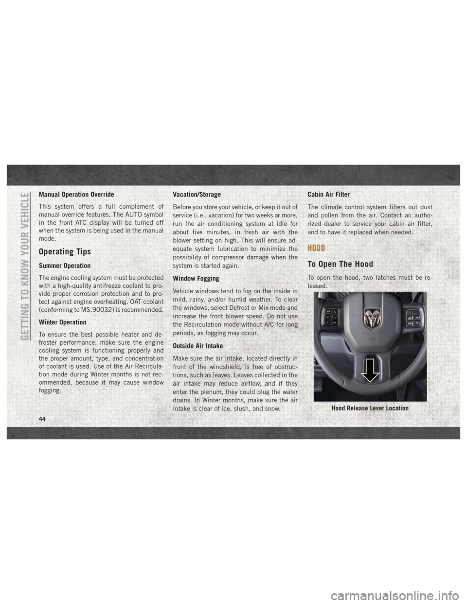
To open the hood, two latches must be re-
leased.
Hood Release Lever Location
GETTING TO KNOW YOUR VEHICLE
44
Page 56 of 298
INSTRUMENT CLUSTER DISPLAY
Your vehicle may be equipped with an instru-
ment cluster display, which offers useful in-
formation to the driver. With the ignition in
the STOP/OFF mode, opening/closing of a
door will activate the display for viewing, and
display the total miles, or kilometers, in the
odometer. Your instrument cluster display is
designed to display important information
about your vehicle’s systems and features.
Using a driver interactive display located on
the instrument panel, your instrument clus-
ter display can show you how systems are
working and give you warnings when they are
not. The steering wheel mounted controls
allow you to scroll through the main menus
and submenus. You can access the specific
information you want and make selections
and adjustments.
Instrument Cluster Display
Controls
The instrument cluster display features a
driver-interactive display that is located in
the instrument cluster.
The instrument cluster display menu items
may consist of the following:
• Speedometer
• Vehicle Info
• Fuel Economy Info
• Trip A
• Trip B
• Audio
• Trailer Tow
• Stored Messages
• Screen Setup
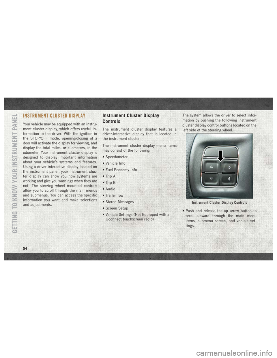
• Vehicle Settings (Not Equipped with aUconnect touchscreen radio) The system allows the driver to select infor-
mation by pushing the following instrument
cluster display control buttons located on the
left side of the steering wheel:
• Push and release the
uparrow button to
scroll upward through the main menu
items, submenu screen, and vehicle set-
tings.
Instrument Cluster Display Controls
GETTING TO KNOW YOUR INSTRUMENT PANEL
54
Page 69 of 298
WARNING!
If you continue operating the vehicle when
the Transmission Temperature Warning
Light is illuminated you could cause the
fluid to boil over, come in contact with hot
engine or exhaust components and cause a
fire.
CAUTION!
Continuous driving with the Transmission
Temperature Warning Light illuminated
will eventually cause severe transmission
damage or transmission failure.
Yellow Indicator Lights
— Rear Fog Indicator — If Equipped
This indicator will illuminate when the rear
fog lights are on.
— TOW/HAUL Indicator Light
This light will illuminate when TOW/HAUL
mode is selected.
— Cargo Light — If Equipped
The cargo light will illuminate when the cargo
light is activated by pushing the cargo light
button on the headlight switch.
— 4WD Low Indicator Light —
If Equipped
This light alerts the driver that the vehicle is
in the four-wheel drive LOW mode. The front
and rear driveshafts are mechanically locked
together forcing the front and rear wheels to
rotate at the same speed. Low range provides
a greater gear reduction ratio to provide in-
creased torque at the wheels.
Refer to “Four-Wheel Drive Operation — If
Equipped” in “Starting And Operating” for
further information on four-wheel drive op-
eration and proper use.
– 4WD Indicator Light —
If Equipped
This light alerts the driver that the vehicle is
in the four-wheel drive mode, and the front
and rear driveshafts are mechanically locked
together forcing the front and rear wheels to
rotate at the same speed.
— 2WD Indicator Light —
If Equipped
This light alerts the driver that the vehicle is
in the two-wheel drive mode.
— Wait To Start Light — If Equipped
The “Wait To Start” telltale will illuminate for
approximately two seconds when the ignition
is turned to the RUN position. It’s duration
may be longer based on colder operating
conditions. Vehicle will not initiate start until
telltale is no longer displayed. Refer to
“Starting The Engine” in “Starting And Op-
erating” for further information.
NOTE:
The “Wait To Start” telltale may not illumi-
nate if the intake manifold temperature is
warm enough.
— Water In Fuel Indicator Light —
If Equipped
The “Water In Fuel Indicator Light” will illu-
minate when there is water detected in the
fuel filters. If this light remains on, DO NOT
start the vehicle before you drain the water
from the fuel filters to prevent engine dam-
67
Page 111 of 298

Frequently Asked Questions About Installing Child Restraints With Seat Belts
Can the head restraints be removed? NoHead restraints may not be removed.
Can the buckle stalk be twisted to tighten the seat belt against the belt path of the child re- straint? Yes – Cinching Latch Plate
No–ALR In positions with cinching latch plates
(CINCH), the buckle stalk may be twisted up to 3 full turns. Do not twist the buckle stalk in a seating position with an ALR retractor.
Installing A Child Restraint With A Switch-
able Automatic Locking Retractor (ALR):
Child restraint systems are designed to be
secured in vehicle seats by lap belts or the lap
belt portion of a lap/shoulder belt.
WARNING!
• Improper installation or failure to prop-
erly secure a child restraint can lead to
failure of the restraint. The child could
be badly injured or killed.
• Follow the child restraint manufacturer’s
directions exactly when installing an in-
fant or child restraint.
1. For Crew Cab Models
Place the child seat in the center of the seating position. For some second row
seats, you may need to recline the seat
and/or raise the head restraint to get a
better fit. If the rear seat can be moved
forward and rearward in the vehicle, you
may wish to move it to its rear-most posi-
tion to make room for the child seat. You
may also move the front seat forward to
allow more room for the child seat.
For Regular Cab Models
Place the child seat in the center of the
seating position. Move the vehicle seat as
far rearward as possible to keep the child
as far from the advanced passenger air
bag as possible.
2. Pull enough of the seat belt webbing from the retractor to pass it through the belt
path of the child restraint. Do not twist the
belt webbing in the belt path. 3. Slide the latch plate into the buckle until
you hear a “click.”
4. Pull on the webbing to make the lap portion tight against the child seat.
5. To lock the seat belt, pull down on the shoulder part of the belt until you have
pulled all the seat belt webbing out of the
retractor. Then, allow the webbing to re-
tract back into the retractor. As the web-
bing retracts, you will hear a clicking
sound. This means the seat belt is now in
the Automatic Locking mode.
6. Try to pull the webbing out of the retractor. If it is locked, you should not be able to
pull out any webbing. If the retractor is not
locked, repeat step 5.
7. Finally, pull up on any excess webbing to
109
Page 118 of 298
The best protection against carbon monoxide
entry into the vehicle body is a properly
maintained engine exhaust system.
Whenever a change is noticed in the sound of
the exhaust system, when exhaust fumes can
be detected inside the vehicle, or when the
underside or rear of the vehicle is damaged,
have a competent mechanic inspect the com-
plete exhaust system and adjacent body ar-
eas for broken, damaged, deteriorated, or
mispositioned parts. Open seams or loose
connections could permit exhaust fumes to
seep into the passenger compartment. In
addition, inspect the exhaust system each
time the vehicle is raised for lubrication or oil
change. Replace as required.
Safety Checks You Should Make
Inside The Vehicle
Seat Belts
Inspect the seat belt system periodically,
checking for cuts, frays, and loose parts.
Damaged parts must be replaced immedi-
ately. Do not disassemble or modify the sys-
tem.Front seat belt assemblies must be replaced
after a collision. Rear seat belt assemblies
must be replaced after a collision if they have
been damaged (i.e., bent retractor, torn web-
bing, etc.). If there is any question regarding
seat belt or retractor condition, replace the
seat belt.
Air Bag Warning Light
The Air Bag warning lightwill turn on for
four to eight seconds as a bulb check when
the ignition switch is first turned to ON/RUN.
If the light is either not on during starting,
stays on, or turns on while driving, have the
system inspected at your authorized dealer as
soon as possible. After the bulb check, this
light will illuminate with a single chime when
a fault with the Air Bag System has been
detected. It will stay on until the fault is
cleared. If the light comes on intermittently
or remains on while driving, have your autho-
rized dealer service the vehicle immediately.
Refer to “Occupant Restraint Systems” in
“Safety” for further information.
Defroster
Check operation by selecting the defrost
mode and place the blower control on high
speed. You should be able to feel the air
directed against the windshield. See your
authorized dealer for service if your defroster
is inoperable.
Floor Mat Safety Information
Always use floor mats designed to fit your
vehicle. Only use a floor mat that does not
interfere with the operation of the accelera-
tor, brake or clutch pedals. Only use a floor
mat that is securely attached using the floor
mat fasteners so it cannot slip out of position
and interfere with the accelerator, brake or
clutch pedals or impair safe operation of your
vehicle in other ways.
WARNING!
An improperly attached, damaged, folded,
or stacked floor mat, or damaged floor mat
fasteners may cause your floor mat to
interfere with the accelerator, brake, or
clutch pedals and cause a loss of vehicle
SAFETY
116
Page 119 of 298
WARNING!
control. To prevent SERIOUS INJURY or
DEATH:
• ALWAYS securely attach
your floor
mat using the floor mat fasteners. DO
NOT install your floor mat upside down
or turn your floor mat over. Lightly pull to
confirm mat is secured using the floor
mat fasteners on a regular basis.
• ALWAYS REMOVE THE EXISTING
FLOOR MAT FROM THE VEHICLE
before installing any other floor mat.
NEVER install or stack an additional
floor mat on top of an existing floor mat.
• ONLY install floor mats designed to fit
your vehicle. NEVER install a floor mat
that cannot be properly attached and
secured to your vehicle. If a floor mat
needs to be replaced, only use a FCA
approved floor mat for the specific
make, model, and year of your vehicle.
• ONLY use the driver’s side floor mat on
the driver’s side floor area. To check for
interference, with the vehicle properly
parked with the engine off, fully depress
the accelerator, the brake, and the
WARNING!
clutch pedal (if present) to check for
interference. If your floor mat interferes
with the operation of any pedal, or is not
secure to the floor, remove the floor mat
from the vehicle and place the floor mat
in your trunk.
• ONLY use the passenger’s side floor mat
on the passenger’s side floor area.
• ALWAYS make sure objects cannot fall
or slide into the driver’s side floor area
when the vehicle is moving. Objects can
become trapped under accelerator,
brake, or clutch pedals and could cause
a loss of vehicle control.
• NEVER place any objects under the floor
mat (e.g., towels, keys, etc.). These ob-
jects could change the position of the
floor mat and may cause interference
with the accelerator, brake, or clutch
pedals.
• If the vehicle carpet has been removed
and re-installed, always properly attach
carpet to the floor and check the floor
mat fasteners are secure to the vehicle
carpet. Fully depress each pedal to
WARNING!
check for interference with the accelera-
tor, brake, or clutch pedals then re-
install the floor mats.
• It is recommended to only use mild soap
and water to clean your floor mats. After
cleaning, always check your floor mat
has been properly installed and is se-
cured to your vehicle using the floor mat
fasteners by lightly pulling mat.
Periodic Safety Checks You
Should Make Outside The Vehicle
Tires
Examine tires for excessive tread wear and
uneven wear patterns. Check for stones,
nails, glass, or other objects lodged in the
tread or sidewall. Inspect the tread for cuts
and cracks. Inspect sidewalls for cuts,
cracks, and bulges. Check the wheel bolts for
tightness. Check the tires (including spare)
for proper cold inflation pressure.
117
Page 121 of 298

STARTING AND OPERATING
STARTING THE ENGINE — GASOLINE
ENGINE................... .120
Normal Starting...............120
STARTING THE ENGINE — 6.7L DIESEL
ENGINE................... .121
Keyless Enter-N-Go — Ignition ......122
Extreme Cold Weather ...........124
NORMAL OPERATION — 6.7L DIESEL
ENGINE................... .125
Cold Weather Precautions.........125
Engine Idling ................125
Stopping The Engine ............126
ENGINE BREAK-IN RECOMMENDATIONS —
GASOLINE ENGINE.............127
ENGINE BREAK-IN RECOMMENDATIONS —
6.7L DIESEL ................ .127
AUTOMATIC TRANSMISSION ......128
Key Ignition Park Interlock........129Brake/Transmission Shift Interlock
System
....................129
Six–Speed Automatic Transmission —
If Equipped .................129
FOUR-WHEEL DRIVE OPERATION —
IF EQUIPPED ............... .131
Electronically Shifted Transfer Case
(Four-Position Switch) — If Equipped .132
SPEED CONTROL..............133
To Activate..................134
To Set A Desired Speed ..........134
To Vary The Speed Setting .........134
To Accelerate For Passing .........135
To Resume Speed .............135
To Deactivate ................135
PARKSENSE FRONT AND REAR PARK
ASSIST — IF EQUIPPED .........136
Cleaning The ParkSense System .....136
PARKVIEW REAR BACK UP CAMERA —
IF EQUIPPED............... .136REFUELING THE VEHICLE — GAS . . . .138
Materials Added To Fuel
..........139
REFUELING THE VEHICLE — DIESEL
CHASSIS CAB MODELS..........139
Diesel Exhaust Fluid............139
Diesel Exhaust Fluid Storage .......140
Adding Diesel Exhaust Fluid .......140
TRAILER TOWING.............142
Trailer Towing Weights (Maximum Trailer
Weight Ratings)...............142
Towing Requirements ...........142
RECREATIONAL TOWING (BEHIND
MOTORHOME, ETC.)............147
Towing This Vehicle Behind Another
Vehicle....................147
Recreational Towing — Two-Wheel Drive
Models .....................147
Recreational Towing — Four-Wheel Drive
Models ....................148
STARTING AND OPERATING
119
Page 122 of 298

STARTING THE ENGINE — GASOLINE
ENGINE
Before starting your vehicle, adjust your seat,
adjust both inside and outside mirrors, and
fasten your seat belt.
The starter should not be operated for more
than 10-second intervals. Waiting a few sec-
onds between such intervals will protect the
starter from overheating.
WARNING!
• When leaving the vehicle, always makesure the keyless ignition node is in the
"OFF" mode, remove the key fob from
the vehicle and lock the vehicle.
• Never leave children alone in a vehicle,
or with access to an unlocked vehicle.
Allowing children to be in a vehicle un-
attended is dangerous for a number of
reasons. A child or others could be seri-
ously or fatally injured. Children should
be warned not to touch the parking
brake, brake pedal or the gear selector.
WARNING!
• Do not leave the key fob in or near thevehicle, or in a location accessible to
children, and do not leave the ignition of
a vehicle equipped with Keyless Enter-
N-Go in the ACC or ON/RUN mode. A
child could operate power windows,
other controls, or move the vehicle.
• Do not leave children or animals inside
parked vehicles in hot weather. Interior
heat build-up may cause serious injury
or death.
Normal Starting
Normal starting of either a warm or cold
engine is obtained without pumping or press-
ing the accelerator pedal. Cycle the ignition
to the RUN position and release when the
engine starts. If the engine fails to start
within 10 seconds, cycle the ignition to the
OFF position, wait five seconds, then repeat
the “Normal Starting” procedure.
To Turn On The Engine Using The ENGINE
START/STOP Button
1. Transmission must be in PARK or
NEUTRAL.
2. Press and hold the brake pedal while pushing the ENGINE START/STOP button
once.
3. The system takes over and attempts to start the vehicle. If the vehicle fails to
start, the starter will disengage automati-
cally after 10 seconds.
4. If you wish to stop the cranking of the engine prior to the engine starting, push
the button again.
NOTE:
Normal starting of either a cold or a warm
engine is obtained without pumping or press-
ing the accelerator pedal.
To Turn Off The Engine Using ENGINE
START/STOP Button
1. Place the gear selector in PARK, then push and release the ENGINE START/
STOP button.
STARTING AND OPERATING
120
Page 123 of 298

2. The ignition switch will return to the OFFmode.
3. If the gear selector is not in PARK (with vehicle stopped) and the ENGINE START/
STOP button is pushed once, the trans-
mission will automatically select PARK
and the engine will turn off, however the
ignition will remain in the ACC mode (NOT
the OFF mode). Never leave a vehicle out
of the PARK position, or it could roll.
4. If the vehicle speed is above 5 mph (8 km/ h), the ENGINE START/STOP button must
be held for two seconds (or three short
pushes in a row) to turn the engine off.
The ignition will remain in the ACC mode
(NOT the OFF mode) if the engine is
turned off when the transmission is not in
PARK.
NOTE:
If the ignition switch is left in the ACC or RUN
(engine not running) mode and the transmis-
sion is in PARK, the system will automatically
time out after 30 minutes of inactivity and
the ignition will switch to the OFF mode.Idle Shutdown — 6.4L Engine Only
This feature can be enabled so that the truck
will automatically shutdown when the truck
has been idling for a set period of time when
the engine is at operating temperature. Idle
time can be set in 5 minute increments
between 5 and 60 minutes. See your local
authorized dealer to enable this feature.
NOTE:
The idle shut down timer is disabled while the
PTO is active.
ENGINE START/STOP Button Functions —
With Driver’s Foot OFF The Brake Pedal (In
PARK Or NEUTRAL Position)
The ENGINE START/STOP button operates
similar to an ignition switch. It has three
positions, OFF, ACC, RUN. To change the
ignition switch positions without starting the
vehicle and use the accessories follow these
steps:
1. Starting with the ignition in the OFF position: 2. Push the ENGINE START/STOP button
once to change the ignition to the ACC
position.
3. Push the ENGINE START/STOP button a second time to change the ignition to the
RUN position.
4. Push the ENGINE START/STOP button a third time to return the ignition to the OFF
position.
STARTING THE ENGINE — 6.7L
DIESEL ENGINE
Before starting your vehicle, adjust your seat,
adjust both inside and outside mirrors, and
fasten your seat belts.
The starter should not be operated for more
than 15-second intervals. Waiting a few min-
utes between such intervals will protect the
starter from overheating.
121