air condition Ram 4500 Chassis Cab 2018 Owner's Manual
[x] Cancel search | Manufacturer: RAM, Model Year: 2018, Model line: 4500 Chassis Cab, Model: Ram 4500 Chassis Cab 2018Pages: 298, PDF Size: 5.88 MB
Page 81 of 298

BeltAlert can be activated or deactivated by
your authorized dealer. FCA US LLC does not
recommend deactivating BeltAlert.
NOTE:
If BeltAlert has been deactivated and the
driver or outboard front seat passenger (if
equipped with outboard front passenger seat
BeltAlert) is unbuckled the Seat Belt Re-
minder Light will turn on and remain on until
the driver and outboard front seat passenger
seat belts are buckled.
Lap/Shoulder Belts
All seating positions except the Crew Cab
front center seating position have combina-
tion lap/shoulder belts.
The seat belt webbing retractor will lock only
during very sudden stops or collisions. This
feature allows the shoulder part of the seat
belt to move freely with you under normal
conditions. However, in a collision the seat
belt will lock and reduce your risk of striking
the inside of the vehicle or being thrown out
of the vehicle.
WARNING!
• Relying on the air bags alone could leadto more severe injuries in a collision. The
air bags work with your seat belt to
restrain you properly. In some collisions,
the air bags won’t deploy at all. Always
wear your seat belt even though you have
air bags.
• In a collision, you and your passengers
can suffer much greater injuries if you
are not properly buckled up. You can
strike the interior of your vehicle or other
passengers, or you can be thrown out of
the vehicle. Always be sure you and
others in your vehicle are buckled up
properly.
• It is dangerous to ride in a cargo area,
inside or outside of a vehicle. In a colli-
sion, people riding in these areas are
more likely to be seriously injured or
killed.
• Do not allow people to ride in any area of
your vehicle that is not equipped with
seats and seat belts.
WARNING!
• Be sure everyone in your vehicle is in aseat and using a seat belt properly. Oc-
cupants, including the driver, should al-
ways wear their seat belts whether or not
an air bag is also provided at their seat-
ing position to minimize the risk of se-
vere injury or death in the event of a
crash.
• Wearing your seat belt incorrectly could
make your injuries in a collision much
worse. You might suffer internal injuries,
or you could even slide out of the seat
belt. Follow these instructions to wear
your seat belt safely and to keep your
passengers safe, too.
• Two people should never be belted into a
single seat belt. People belted together
can crash into one another in a collision,
hurting one another badly. Never use a
lap/shoulder belt or a lap belt for more
than one person, no matter what their
size.
79
Page 90 of 298

ON/RUN position. If the ignition switch is in
the OFF position or in the ACC position, the
air bag system is not on and the air bags will
not inflate.
The ORC contains a backup power supply
system that may deploy the air bag system
even if the battery loses power or it becomes
disconnected prior to deployment.
The ORC turns on the Air Bag Warning Light
in the instrument panel for approximately
four to eight seconds for a self-check when
the ignition switch is first in the ON/RUN
position. After the self-check, the Air Bag
Warning Light will turn off. If the ORC detects
a malfunction in any part of the system, it
turns on the Air Bag Warning Light, either
momentarily or continuously. A single chime
will sound to alert you if the light comes on
again after initial startup.
The ORC also includes diagnostics that will
illuminate the instrument panel Air Bag
Warning Light if a malfunction is detected
that could affect the air bag system. The
diagnostics also record the nature of the
malfunction. While the air bag system isdesigned to be maintenance free, if any of
the following occurs, have an authorized
dealer service the air bag system immedi-
ately.
• The Air Bag Warning Light does not come
on during the four to eight seconds when
the ignition switch is first in the ON/RUN
position.
• The Air Bag Warning Light remains on after the four to eight-second interval.
• The Air Bag Warning Light comes on inter- mittently or remains on while driving.
NOTE:
If the speedometer, tachometer, or any en-
gine related gauges are not working, the Oc-
cupant Restraint Controller (ORC) may also
be disabled. In this condition the air bags
may not be ready to inflate for your protec-
tion. Have an authorized dealer service the
air bag system immediately.WARNING!
Ignoring the Air Bag Warning Light in your
instrument panel could mean you won’t
have the air bag system to protect you in a
collision. If the light does not come on as a
bulb check when the ignition is first
turned on, stays on after you start the
vehicle, or if it comes on as you drive, have
an authorized dealer service the air bag
system immediately.
Front Air Bags
This vehicle has front air bags and lap/
shoulder belts for both the driver and front
passenger. The front air bags are a supple-
ment to the seat belt restraint systems. The
driver front air bag is mounted in the center
of the steering wheel. The passenger front air
bag is mounted in the instrument panel,
above the glove compartment. The words
“SRS AIRBAG” or “AIRBAG” are embossed
on the air bag covers.
SAFETY
88
Page 118 of 298
The best protection against carbon monoxide
entry into the vehicle body is a properly
maintained engine exhaust system.
Whenever a change is noticed in the sound of
the exhaust system, when exhaust fumes can
be detected inside the vehicle, or when the
underside or rear of the vehicle is damaged,
have a competent mechanic inspect the com-
plete exhaust system and adjacent body ar-
eas for broken, damaged, deteriorated, or
mispositioned parts. Open seams or loose
connections could permit exhaust fumes to
seep into the passenger compartment. In
addition, inspect the exhaust system each
time the vehicle is raised for lubrication or oil
change. Replace as required.
Safety Checks You Should Make
Inside The Vehicle
Seat Belts
Inspect the seat belt system periodically,
checking for cuts, frays, and loose parts.
Damaged parts must be replaced immedi-
ately. Do not disassemble or modify the sys-
tem.Front seat belt assemblies must be replaced
after a collision. Rear seat belt assemblies
must be replaced after a collision if they have
been damaged (i.e., bent retractor, torn web-
bing, etc.). If there is any question regarding
seat belt or retractor condition, replace the
seat belt.
Air Bag Warning Light
The Air Bag warning lightwill turn on for
four to eight seconds as a bulb check when
the ignition switch is first turned to ON/RUN.
If the light is either not on during starting,
stays on, or turns on while driving, have the
system inspected at your authorized dealer as
soon as possible. After the bulb check, this
light will illuminate with a single chime when
a fault with the Air Bag System has been
detected. It will stay on until the fault is
cleared. If the light comes on intermittently
or remains on while driving, have your autho-
rized dealer service the vehicle immediately.
Refer to “Occupant Restraint Systems” in
“Safety” for further information.
Defroster
Check operation by selecting the defrost
mode and place the blower control on high
speed. You should be able to feel the air
directed against the windshield. See your
authorized dealer for service if your defroster
is inoperable.
Floor Mat Safety Information
Always use floor mats designed to fit your
vehicle. Only use a floor mat that does not
interfere with the operation of the accelera-
tor, brake or clutch pedals. Only use a floor
mat that is securely attached using the floor
mat fasteners so it cannot slip out of position
and interfere with the accelerator, brake or
clutch pedals or impair safe operation of your
vehicle in other ways.
WARNING!
An improperly attached, damaged, folded,
or stacked floor mat, or damaged floor mat
fasteners may cause your floor mat to
interfere with the accelerator, brake, or
clutch pedals and cause a loss of vehicle
SAFETY
116
Page 124 of 298

WARNING!
• Do not leave children or animals insideparked vehicles in hot weather. Interior
heat build up may cause serious injury
or death.
• When leaving the vehicle, always make
sure the keyless ignition node is in the
“OFF” mode, remove the key fob from
the vehicle and lock the vehicle.
• Never leave children alone in a vehicle,
or with access to an unlocked vehicle.
Allowing children to be in a vehicle un-
attended is dangerous for a number of
reasons. A child or others could be seri-
ously or fatally injured. Children should
be warned not to touch the parking
brake, brake pedal or the gear selector.
• Do not leave the key fob in or near the
vehicle, or in a location accessible to
children, and do not leave the ignition of
a vehicle equipped with Keyless Enter-
N-Go in the ACC or ON/RUN mode. A
child could operate power windows,
other controls, or move the vehicle.
Keyless Enter-N-Go — Ignition
This feature allows the driver to operate the
ignition switch with the push of a button, as
long as the Remote Start/Keyless Enter-N-Go
key fob is in the passenger compartment.
Normal Starting
Using The ENGINE START/STOP Button
1. The transmission must be in PARK or
NEUTRAL.
2. Press and hold the brake pedal while pushing the ENGINE START/STOP button
once.
3. The system takes over and attempts to start the vehicle. If the vehicle fails to
start, the starter will disengage automati-
cally after 25 seconds.
4. If you wish to stop the cranking of the engine prior to the engine starting, re-
move your foot from the brake pedal and
push the button again. NOTE:
• Normal starting of either a cold or a warm
engine is obtained without pumping or
pressing the accelerator pedal.
• Under cold weather conditions, the engine may not immediately crank if the "Wait To
Start" telltale is illuminated. This is normal
operation. For vehicles equipped with Key-
less Enter-N-Go, the vehicle will automati-
cally crank when the "Wait To Start" time
has elapsed. See the section "Starting Pro-
cedure Engine Manifold Air Temperature
0°F to 66°F (18° C to 19°C)" in the Diesel
Supplement for more information.
To Turn Off The Engine Using ENGINE START/
STOP Button
1. Place the gear selector in PARK, then push and release the ENGINE START/
STOP button.
2. The ignition will return to the OFF mode.
3. If the gear selector is not in PARK and the ENGINE START/STOP button is pushed
once, the instrument cluster will display a
STARTING AND OPERATING
122
Page 148 of 298
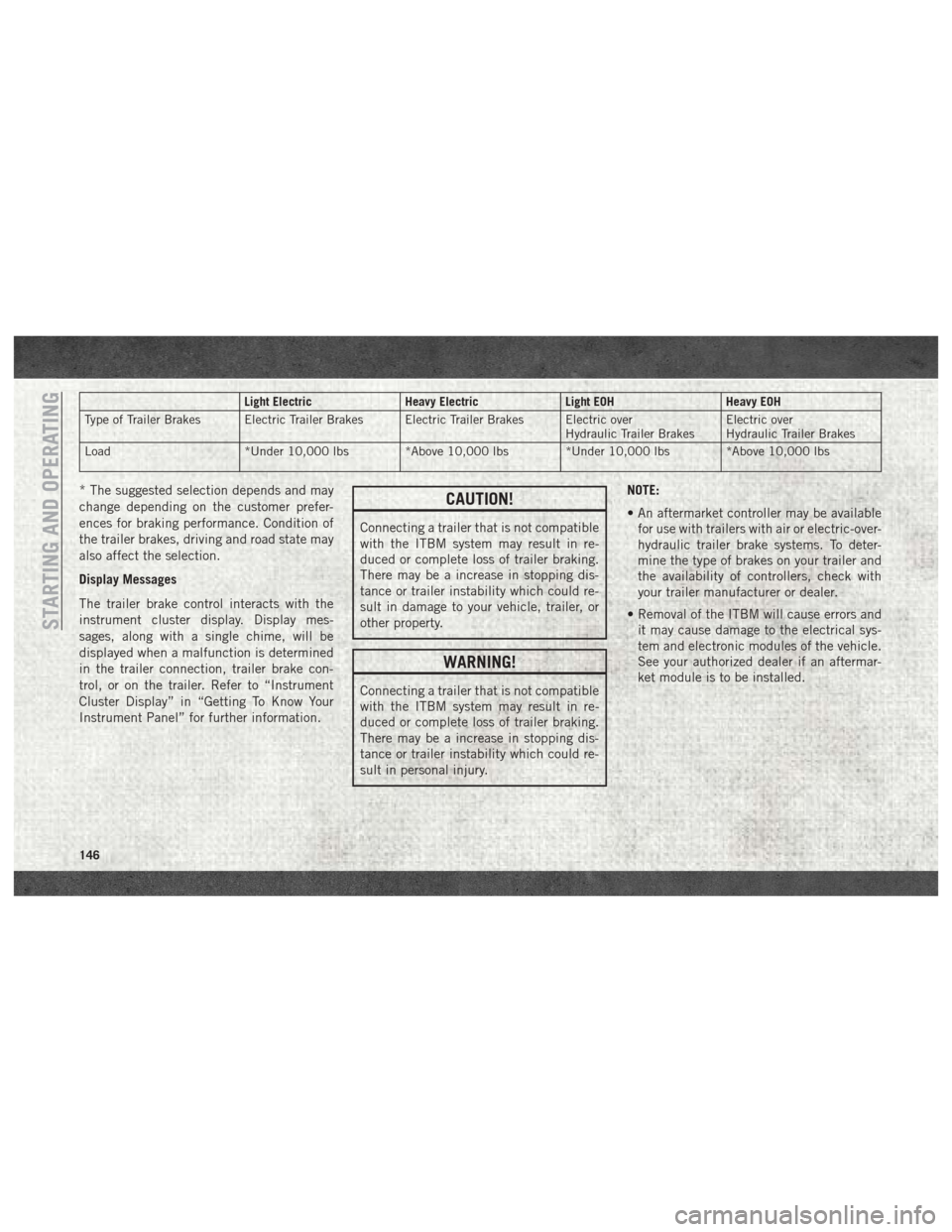
Light ElectricHeavy ElectricLight EOHHeavy EOH
Type of Trailer Brakes Electric Trailer Brakes Electric Trailer Brakes Electric over Hydraulic Trailer BrakesElectric over
Hydraulic Trailer Brakes
Load *Under 10,000 lbs *Above 10,000 lbs *Under 10,000 lbs *Above 10,000 lbs
* The suggested selection depends and may
change depending on the customer prefer-
ences for braking performance. Condition of
the trailer brakes, driving and road state may
also affect the selection.
Display Messages
The trailer brake control interacts with the
instrument cluster display. Display mes-
sages, along with a single chime, will be
displayed when a malfunction is determined
in the trailer connection, trailer brake con-
trol, or on the trailer. Refer to “Instrument
Cluster Display” in “Getting To Know Your
Instrument Panel” for further information.CAUTION!
Connecting a trailer that is not compatible
with the ITBM system may result in re-
duced or complete loss of trailer braking.
There may be a increase in stopping dis-
tance or trailer instability which could re-
sult in damage to your vehicle, trailer, or
other property.
WARNING!
Connecting a trailer that is not compatible
with the ITBM system may result in re-
duced or complete loss of trailer braking.
There may be a increase in stopping dis-
tance or trailer instability which could re-
sult in personal injury. NOTE:
• An aftermarket controller may be available
for use with trailers with air or electric-over-
hydraulic trailer brake systems. To deter-
mine the type of brakes on your trailer and
the availability of controllers, check with
your trailer manufacturer or dealer.
• Removal of the ITBM will cause errors and it may cause damage to the electrical sys-
tem and electronic modules of the vehicle.
See your authorized dealer if an aftermar-
ket module is to be installed.
STARTING AND OPERATING
146
Page 160 of 298
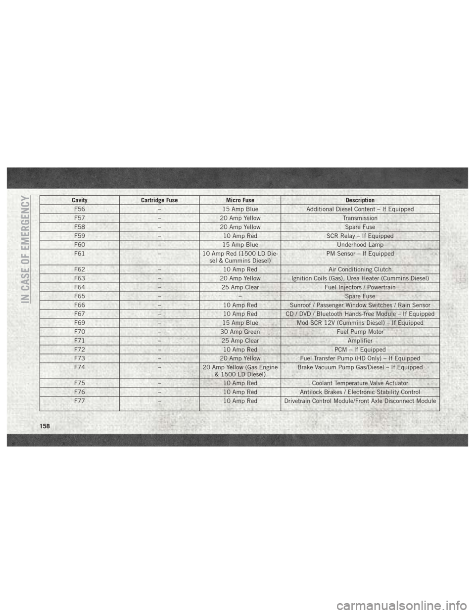
CavityCartridge Fuse Micro Fuse Description
F56 –15 Amp Blue Additional Diesel Content – If Equipped
F57 –20 Amp Yellow Transmission
F58 –20 Amp Yellow Spare Fuse
F59 –10 Amp Red SCR Relay – If Equipped
F60 –15 Amp Blue Underhood Lamp
F61 –10 Amp Red (1500 LD Die-
sel & Cummins Diesel) PM Sensor – If Equipped
F62 –10 Amp Red Air Conditioning Clutch
F63 –20 Amp Yellow Ignition Coils (Gas), Urea Heater (Cummins Diesel)
F64 –25 Amp Clear Fuel Injectors / Powertrain
F65 –– Spare Fuse
F66 –10 Amp Red Sunroof / Passenger Window Switches / Rain Sensor
F67 –10 Amp Red CD / DVD / Bluetooth Hands-free Module – If Equipped
F69 –15 Amp Blue Mod SCR 12V (Cummins Diesel) – If Equipped
F70 –30 Amp Green Fuel Pump Motor
F71 –25 Amp Clear Amplifier
F72 –10 Amp Red PCM – If Equipped
F73 –20 Amp Yellow Fuel Transfer Pump (HD Only) – If Equipped
F74 –20 Amp Yellow (Gas Engine
& 1500 LD Diesel) Brake Vacuum Pump Gas/Diesel – If Equipped
F75 –10 Amp Red Coolant Temperature Valve Actuator
F76 –10 Amp Red Antilock Brakes / Electronic Stability Control
F77 –10 Amp Red Drivetrain Control Module/Front Axle Disconnect Module
IN CASE OF EMERGENCY
158
Page 169 of 298
• In city traffic — while stopped, place thetransmission in NEUTRAL, but do not in-
crease the engine idle speed while prevent-
ing vehicle motion with the brakes.
NOTE:
There are steps that you can take to slow
down an impending overheat condition:
• If your air conditioner (A/C) is on, turn it off. The A/C system adds heat to the engine
cooling system and turning the A/C off can
help remove this heat.
• You can also turn the temperature control to maximum heat, the mode control to floor
and the blower control to high. This allows
the heater core to act as a supplement to
the radiator and aids in removing heat from
the engine cooling system.
WARNING!
You or others can be badly burned by hot
engine coolant (antifreeze) or steam from
your radiator. If you see or hear steam
coming from under the hood, do not open
the hood until the radiator has had time to
cool. Never try to open a cooling system
WARNING!
pressure cap when the radiator or coolant
bottle is hot.
CAUTION!
Driving with a hot cooling system could
damage your vehicle. If the temperature
gauge reads HOT (H), pull over and stop
the vehicle. Idle the vehicle with the air
conditioner turned off until the pointer
drops back into the normal range. If the
pointer remains on HOT (H), and you hear
continuous chimes, turn the engine off
immediately and call for service.
GEAR SELECTOR OVERRIDE
If a malfunction occurs and the gear selector
cannot be moved out of the PARK position,
you can use the following procedure to tem-
porarily move the gear selector: 1. Turn the engine OFF.
2. Firmly apply the parking brake.
3. Tilt the steering wheel to the full up
position.
4. Press and maintain firm pressure on the brake pedal.
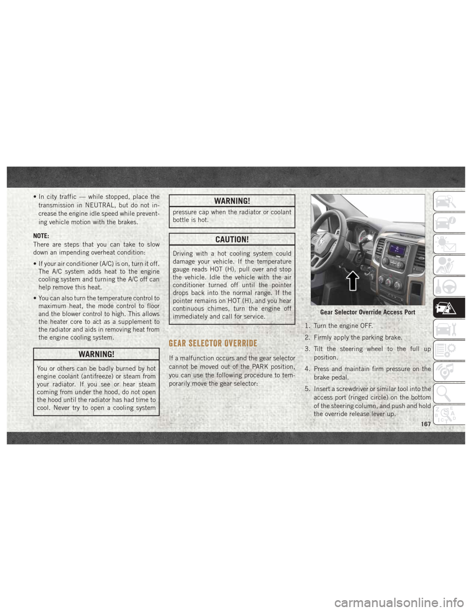
5. Insert a screwdriver or similar tool into the access port (ringed circle) on the bottom
of the steering column, and push and hold
the override release lever up.
Gear Selector Override Access Port
167
Page 177 of 298
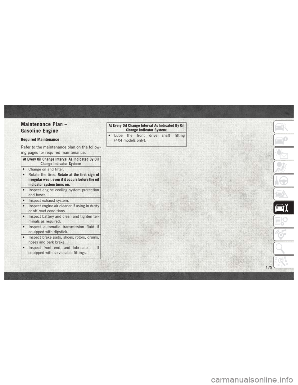
Maintenance Plan –
Gasoline Engine
Required Maintenance
Refer to the maintenance plan on the follow-
ing pages for required maintenance.
At Every Oil Change Interval As Indicated By OilChange Indicator System:
• Change oil and filter.
• Rotate the tires. Rotate at the first sign of
irregular wear, even if it occurs before the oil
indicator system turns on.
• Inspect engine cooling system protection and hoses.
• Inspect exhaust system.
• Inspect engine air cleaner if using in dusty or off-road conditions.
• Inspect battery and clean and tighten ter- minals as required.
• Inspect automatic transmission fluid if equipped with dipstick.
• Inspect brake pads, shoes, rotors, drums, hoses and park brake.
• Inspect front end, and lubricate — If equipped with serviceable fittings.
At Every Oil Change Interval As Indicated By Oil Change Indicator System:
• Lube the front drive shaft fitting (4X4 models only).
175
Page 188 of 298
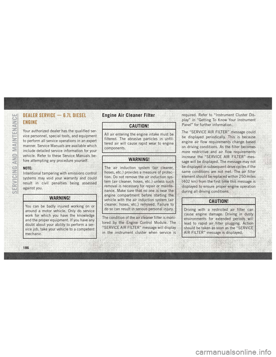
DEALER SERVICE — 6.7L DIESEL
ENGINE
Your authorized dealer has the qualified ser-
vice personnel, special tools, and equipment
to perform all service operations in an expert
manner. Service Manuals are available which
include detailed service information for your
vehicle. Refer to these Service Manuals be-
fore attempting any procedure yourself.
NOTE:
Intentional tampering with emissions control
systems may void your warranty and could
result in civil penalties being assessed
against you.
WARNING!
You can be badly injured working on or
around a motor vehicle. Only do service
work for which you have the knowledge
and the proper equipment. If you have any
doubt about your ability to perform a ser-
vice job, take your vehicle to a competent
mechanic.
Engine Air Cleaner Filter
CAUTION!
All air entering the engine intake must be
filtered. The abrasive particles in unfil-
tered air will cause rapid wear to engine
components.
WARNING!
The air induction system (air cleaner,
hoses, etc.) provides a measure of protec-
tion. Do not remove the air induction sys-
tem (air cleaner, hoses, etc.) unless such
removal is necessary for repair or mainte-
nance. Make sure that no one is near the
engine compartment before starting the
vehicle with the air induction system (air
cleaner, hoses, etc.) removed. Failure to
do so can result in serious personal injury.
The condition of the air cleaner filter is moni-
tored by the Engine Control Module. The
“SERVICE AIR FILTER” message will display
in the instrument cluster when service is required. Refer to “Instrument Cluster Dis-
play” in “Getting To Know Your Instrument
Panel” for further information.
The “SERVICE AIR FILTER” message could
be displayed periodically. This is because
engine air flow requirements change based
on driving conditions. As the filter becomes
more restrictive and air flow requirements
increase the “SERVICE AIR FILTER” mes-
sage will be displayed. The message may not
be displayed in subsequent drive cycles if the
same conditions are not met. The air filter
element should be replaced within 250 miles
(402 km) from the first time this message is
displayed to ensure proper engine operation
during all driving conditions.
CAUTION!
Driving with a restricted air filter can
cause engine damage. Driving in dusty
environments for extended periods will
lead to rapid air filter plugging. Action
should be taken as soon as the “SERVICE
AIR FILTER” message is displayed.
SERVICING AND MAINTENANCE
186
Page 192 of 298

Priming If The Engine Has Run
Out Of Fuel
WARNING!
Do not open the high pressure fuel system
with the engine running. Engine operation
causes high fuel pressure. High pressure
fuel spray can cause serious injury or
death.
1. Add a substantial amount of fuel to the tank, approximately 2 to 5 gal (8L to
19L).
2. Turn ignition switch to the start position to engage starter for one second, return ig-
nition switch to run position. This will
activate in tank fuel pump for approxi-
mately 15 seconds. Repeat this process
twice.
3. Start the engine using the “Normal Start- ing” procedure. Refer to “Starting Proce-
dures” in “Starting and Operating” for
further information.
CAUTION!
Do not engage the starter motor for more
than 15 seconds at a time. Allow two
minutes between the cranking intervals.
NOTE:
The engine may run rough until the air is
forced from all the fuel lines.
WARNING!
Do not use alcohol or gasoline as a fuel
blending agent. They can be unstable un-
der certain conditions and be hazardous or
explosive when mixed with diesel fuel.
CAUTION!
Due to lack of lubricants in alcohol or
gasoline, the use of these fuels can cause
damage to the fuel system. NOTE:
• A maximum blend of 5% biodiesel, meet-
ing ASTM specification D-975 may be used
with your Cummins diesel engine. (Chassis
Cab models not configured with B20 capa-
bility.)
• A maximum blend of 20% biodiesel, meet- ing ASTM specification D-7467 may be
used with your Cummins diesel engine.
(Pickup models and Chassis Cab models
configured with B20 capability.)
• Use of biodiesel mixture in excess of 20% can negatively impact the fuel filter's abil-
ity to separate water from the fuel, resulting
in high pressure fuel system corrosion or
damage.
• Ethanol blends are not recommended or approved for use with your Cummins diesel
engine.
• In addition, commercially available fuel ad- ditives are not necessary for the proper
operation of your Cummins diesel engine.
SERVICING AND MAINTENANCE
190