instrument cluster Ram 4500 Chassis Cab 2018 Owner's Manual
[x] Cancel search | Manufacturer: RAM, Model Year: 2018, Model line: 4500 Chassis Cab, Model: Ram 4500 Chassis Cab 2018Pages: 298, PDF Size: 5.88 MB
Page 50 of 298

2. Return to the vehicle and push the pro-grammed HomeLink button three times
(holding the button for two seconds each
time). The instrument cluster display will
show “CHANNEL # TRANSMIT”. If the
garage door opener motor operates, pro-
gramming is complete.
3. Push the programmed HomeLink button to confirm that the garage door opener
motor operates. If the garage door opener
motor does not operate, repeat the final
steps for the rolling code procedure.
Non-Rolling Code Garage Door Opener Final
Steps
1. Push and hold the programmed HomeLink button and observe the instru-
ment cluster display. If the instrument
cluster display shows the “CHANNEL #
TRANSMIT,” programming is complete.
2. Push the programmed HomeLink button to confirm that the garage door opener
motor operates. If the garage door opener
motor does not operate, repeat the steps
from the beginning.WARNING!
• Your motorized door or gate will openand close while you are programming
the universal transceiver. Do not pro-
gram the transceiver if people or pets are
in the path of the door or gate.
• Do not run your vehicle in a closed
garage or confined area while program-
ming the transceiver. Exhaust gas from
your vehicle contains Carbon Monoxide
(CO) which is odorless and colorless.
Carbon Monoxide is poisonous when in-
haled and can cause you and others to
be severely injured or killed.
Programming HomeLink To A
Miscellaneous Device
Refer to “Programming HomeLink To A Ga-
rage Door Opener” for the procedure on how
to program HomeLink to a miscellaneous
device, as it follows the same procedure. Be
sure to determine if the device has a rolling
code, or non-rolling code before beginning
the programming process. NOTE:
Canadian radio frequency laws require trans-
mitter signals to time-out (or quit) after sev-
eral seconds of transmission, which may not
be long enough for HomeLink to pick up the
signal during programming. Similar to this
Canadian law, some U.S. gate operators are
designed to time-out in the same manner.
The procedure may need to be preformed
multiple times to successfully pair the device
to your HomeLink buttons.
Reprogramming A Single
HomeLink Button
To reprogram a single HomeLink button that
has been previously trained, without erasing
all the channels, follow the procedure below.
Be sure to determine whether the new device
you want to program the HomeLink button to
has a Rolling Code, or Non-rolling Code.
1. Cycle the ignition to the ON/RUN
position.
GETTING TO KNOW YOUR VEHICLE
48
Page 51 of 298
NOTE:
For vehicle’s equipped with Keyless Enter-
N-Go, place the ignition in the RUN posi-
tion with the Engine ON. Make sure to
program HomeLink with the vehicle out-
side of the garage, or with the garage door
open at all times.
2. Push and hold the desired HomeLink but- ton until the instrument cluster display
shows the “CHANNEL # TRAINING” mes-
sage. Do not release the button.
3. Without releasing the button, proceed with
Step 2 in “Programming HomeLink To A
Garage Door Opener” and follow all re-
maining steps.
General Information
The following regulatory statement applies to
all Radio Frequency (RF) devices equipped in
this vehicle:
This device complies with Part 15 of the FCC
Rules and with Industry Canada license-
exempt RSS standard(s). Operation is sub-
ject to the following two conditions:
1. This device may not cause harmful inter- ference, and 2. This device must accept any interference
received, including interference that may
cause undesired operation.
NOTE:
Changes or modifications not expressly ap-
proved by the party responsible for compli-
ance could void the user’s authority to oper-
ate the equipment.
INTERNAL EQUIPMENT
Electrical Power Outlets
The auxiliary 12 Volt (13 Amp) power outlets
can provide power for in-cab accessories de-
signed for use with the standard “cigar
lighter” plug. The 12 Volt power outlets and
USB Port (Charge Only) have a cap attached
to the outlet indicating “12V DC,” together
with either a key symbol, battery symbol, or
USB symbol.
A key symbol indicates that the key must be
in the ON/RUN or ACC positions for the outlet
to provide power. The battery symbol indi-
cates that the outlet is connected to the
battery, and can provide power at all times. NOTE:
To ensure proper operation, a Mopar knob
and element must be used.
CAUTION!
• Do not exceed the maximum power of
160 Watts (13 Amps) at 12 Volts. If the
160 Watts (13 Amps) power rating is
exceeded, the fuse protecting the sys-
tem will need to be replaced.
• Power outlets are designed for accessory
plugs only. Do not insert any other object
in the power outlets as this will damage
the outlet and blow the fuse. Improper
use of the power outlet can cause dam-
age not covered by your New Vehicle
Limited Warranty.
49
Page 55 of 298

GETTING TO KNOW YOUR INSTRUMENT PANEL
INSTRUMENT CLUSTER DISPLAY.....54
Instrument Cluster Display Controls ....54
Diesel Messages And Warnings —
6.7L Cummins Diesel Engine ........55
Oil Life Reset .................59
Instrument Cluster Display
Programmable Features ...........59
WARNING LIGHTS AND MESSAGES ....61
Red Warning Lights..............61
Yellow Warning Lights ............63
Yellow Indicator Lights ............67
Green Indicator Lights ............68
White Indicator Lights ............68
Blue Indicator Lights .............68
ONBOARD DIAGNOSTIC SYSTEM —
OBDII .....................69
Onboard Diagnostic System (OBD II)
Cybersecurity.................69
GETTING TO KNOW YOUR INSTRUMENT PANEL
53
Page 56 of 298
INSTRUMENT CLUSTER DISPLAY
Your vehicle may be equipped with an instru-
ment cluster display, which offers useful in-
formation to the driver. With the ignition in
the STOP/OFF mode, opening/closing of a
door will activate the display for viewing, and
display the total miles, or kilometers, in the
odometer. Your instrument cluster display is
designed to display important information
about your vehicle’s systems and features.
Using a driver interactive display located on
the instrument panel, your instrument clus-
ter display can show you how systems are
working and give you warnings when they are
not. The steering wheel mounted controls
allow you to scroll through the main menus
and submenus. You can access the specific
information you want and make selections
and adjustments.
Instrument Cluster Display
Controls
The instrument cluster display features a
driver-interactive display that is located in
the instrument cluster.
The instrument cluster display menu items
may consist of the following:
• Speedometer
• Vehicle Info
• Fuel Economy Info
• Trip A
• Trip B
• Audio
• Trailer Tow
• Stored Messages
• Screen Setup
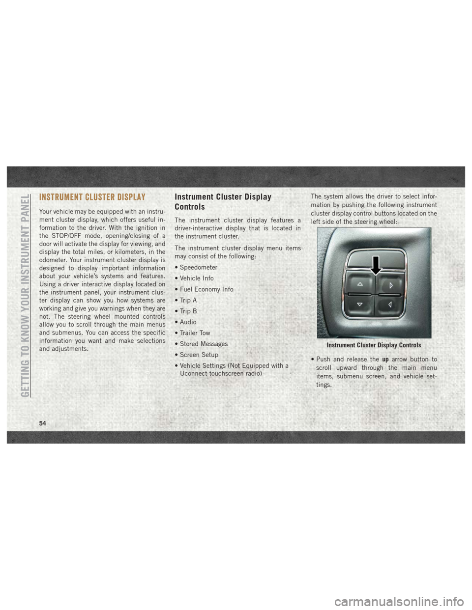
• Vehicle Settings (Not Equipped with aUconnect touchscreen radio) The system allows the driver to select infor-
mation by pushing the following instrument
cluster display control buttons located on the
left side of the steering wheel:
• Push and release the
uparrow button to
scroll upward through the main menu
items, submenu screen, and vehicle set-
tings.
Instrument Cluster Display Controls
GETTING TO KNOW YOUR INSTRUMENT PANEL
54
Page 57 of 298

• Push and release thedownarrow button to
scroll downward through the main menu
items, submenu screen, and vehicle set-
tings.
• Push and release the rightarrow button to
access/select the information screens or
submenu screens of a main menu item.
Push and hold the RIGHT arrow button for
two seconds to reset displayed/selected
features that can be reset.
• Push and release the leftarrow button to
access/select the information screens, sub-
menu screens of a main menu item, or to
return to the main menu.
Diesel Messages And Warnings —
6.7L Cummins Diesel Engine
Diesel Particulate Filter (DPF) Messages
The Cummins diesel engine meets all diesel
emissions standards, resulting in one of the
lowest emitting diesel engines ever pro-
duced. To achieve these emissions stan-
dards, your vehicle is equipped with a state-
of-the-art engine and exhaust system. These
systems are seamlessly integrated into your vehicle and managed by the Powertrain Con-
trol Module (PCM). The PCM manages engine
combustion to allow the exhaust system’s
catalyst to trap and burn Particulate Matter
(PM) pollutants, with no input or interaction
on your part.
WARNING!
A hot exhaust system can start a fire if you
park over materials that can burn. Such
materials might be grass or leaves coming
into contact with your exhaust system. Do
not park or operate your vehicle in areas
where your exhaust system can contact
anything that can burn.
Your vehicle has the ability to alert you to
additional maintenance required on your ve-
hicle or engine. The following messages may
display in your instrument cluster display:
• Perform Service — Your vehicle will require
emissions maintenance at a set interval. To
help remind you when this maintenance is
due, the instrument cluster display will
display “Perform Service”. When the “Per-
form Service” message is displayed in the
instrument cluster display it is necessary to have the emissions maintenance per-
formed. Emissions maintenance may in-
clude replacing the Closed Crankcase Ven-
tilation (CCV) filter element. The procedure
for clearing and resetting the "Perform Ser-
vice" indicator message is located in the
appropriate Service Information.
• Exhaust System — Regeneration Required
Now — "Exhaust Filter XX% Full Safely
Drive at Highway Speeds to Remedy" will be
displayed in the instrument cluster display
if the exhaust particulate filter reaches
80% of its maximum storage capacity. Un-
der conditions of exclusive short duration
and low speed driving cycles, your Cum-
mins diesel engine and exhaust after-
treatment system may never reach the con-
ditions required to remove the trapped PM.
If this occurs, the “Exhaust Filter XX% Full
Safely Drive at Highway Speeds to Rem-
edy” message will be displayed in the in-
strument cluster display. If this message is
displayed, you will hear one chime to assist
in alerting you of this condition
By simply driving your vehicle at highway
speeds for as little as 45 minutes, you can
remedy the condition in the particulate filter
55
Page 61 of 298
under demanding hot or high altitude condi-
tions. If the instrument cluster display dis-
plays the message “Active Airbox Service
Required See Dealer”, vehicle performance
may be reduced until service is performed by
an authorized RAM dealer.
Oil Life Reset
Your vehicle is equipped with an engine oil
change indicator system. The “Oil Change
Required” message will display in the instru-
ment cluster display after a single chime has
sounded, to indicate the next scheduled oil
change interval. The engine oil change indi-
cator system is duty cycle based, which
means the engine oil change interval may
fluctuate, dependent upon your personal
driving style.
NOTE:
Use the steering wheel instrument cluster
display controls for the following proce-
dure(s).Vehicles Equipped With Passive Entry
1. Without pushing the brake pedal, push
the ENGINE START/STOP button and
place the ignition to the ON/RUN position
(do not start the engine).
2. Push and release the downarrow button to
scroll downward through the main menu
to “Vehicle Info.”
3. Push and release the rightarrow button to
access the ”Vehicle Info” screen, then
scroll up or down to select “Oil Life.”
4. Push and hold the rightarrow button to
select “Reset”.
5. Push and release the downarrow button to
select “Yes,” then push and release the
right arrow button to select reset of the Oil
Life to 100%.
6. Push and release the uparrow button to
exit the instrument cluster display screen. Vehicles Not Equipped With Passive Entry
1. Without pushing the brake pedal, cycle
the ignition to the ON/RUN position (do
not start the engine).
2. Push and release the downarrow button to
scroll downward through the main menu
to “Vehicle Info.”
3. Push and release the rightarrow button to
access the “Vehicle Info” screen then
scroll up or down to select “Oil Life.”
4. Push and hold the rightarrow button to
select “YES” by pushing the rightarrow
then push and release the rightarrow
button to select reset of the Oil Life to
100%.
5. Push and release the uparrow button to
exit the instrument cluster display screen.
NOTE:
If the indicator message illuminates when
you start the vehicle, the Oil Life indicator
system did not reset. If necessary, repeat this
procedure.
59
Page 62 of 298
Instrument Cluster Display Programmable Features
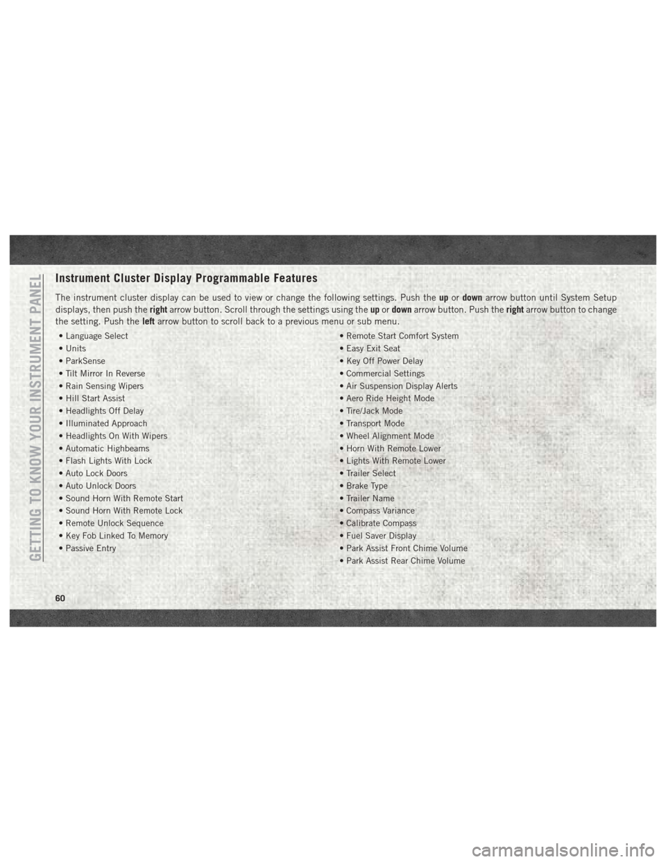
The instrument cluster display can be used to view or change the following settings. Push theupordown arrow button until System Setup
displays, then push the rightarrow button. Scroll through the settings using the upordown arrow button. Push the rightarrow button to change
the setting. Push the leftarrow button to scroll back to a previous menu or sub menu.
• Language Select • Remote Start Comfort System
• Units • Easy Exit Seat
• ParkSense • Key Off Power Delay
• Tilt Mirror In Reverse • Commercial Settings
• Rain Sensing Wipers • Air Suspension Display Alerts
• Hill Start Assist • Aero Ride Height Mode
• Headlights Off Delay • Tire/Jack Mode
• Illuminated Approach • Transport Mode
• Headlights On With Wipers • Wheel Alignment Mode
• Automatic Highbeams • Horn With Remote Lower
• Flash Lights With Lock • Lights With Remote Lower
• Auto Lock Doors • Trailer Select
• Auto Unlock Doors • Brake Type
• Sound Horn With Remote Start • Trailer Name
• Sound Horn With Remote Lock • Compass Variance
• Remote Unlock Sequence • Calibrate Compass
• Key Fob Linked To Memory • Fuel Saver Display
• Passive Entry • Park Assist Front Chime Volume
• Park Assist Rear Chime Volume
GETTING TO KNOW YOUR INSTRUMENT PANEL
60
Page 66 of 298
Certain conditions, such as a loose or missing
gas cap, poor quality fuel, etc., may illumi-
nate the light after engine start. The vehicle
should be serviced if the light stays on
through several typical driving styles. In most
situations, the vehicle will drive normally and
will not require towing.
When the engine is running, the MIL may
flash to alert serious conditions that could
lead to immediate loss of power or severe
catalytic converter damage. The vehicle
should be serviced as soon as possible if this
occurs.
WARNING!
A malfunctioning catalytic converter, as
referenced above, can reach higher tem-
peratures than in normal operating condi-
tions. This can cause a fire if you drive
slowly or park over flammable substances
such as dry plants, wood, cardboard, etc.
This could result in death or serious injury
to the driver, occupants or others.
CAUTION!
Prolonged driving with the Malfunction
Indicator Light (MIL) on could cause dam-
age to the vehicle control system. It also
could affect fuel economy and driveability.
If the MIL is flashing, severe catalytic
converter damage and power loss will soon
occur. Immediate service is required.
— Electronic Stability Control (ESC)
Active Warning Light — If Equipped
This light will indicate when the Electronic
Stability Control system is Active. The “ESC
Indicator Light” in the instrument cluster will
come on when the ignition is placed in the
ON/RUN or ACC/ON/RUN position, and when
ESC is activated. It should go out with the
engine running. If the “ESC Indicator Light”
comes on continuously with the engine run-
ning, a malfunction has been detected in the
ESC system. If this light remains on after
several ignition cycles, and the vehicle has
been driven several miles (kilometers) at speeds greater than 30 mph (48 km/h), see
your authorized dealer as soon as possible to
have the problem diagnosed and corrected.
• The “ESC Off Indicator Light” and the
“ESC Indicator Light” come on momen-
tarily each time the ignition is placed in the
ON/RUN or ACC/ON/RUN position.
• The ESC system will make buzzing or click- ing sounds when it is active. This is normal;
the sounds will stop when ESC becomes
inactive.
• This light will come on when the vehicle is in an ESC event.
— Electronic Stability Control (ESC) Off
Warning Light — If Equipped
This light indicates the Electronic Stability
Control (ESC) is off.
Each time the ignition is turned to ON/RUN
or ACC/ON/RUN, the ESC system will be on,
even if it was turned off previously.
— Low Washer Fluid Warning Light —
If Equipped
This indicator will illuminate when the wind-
shield washer fluid is low.
GETTING TO KNOW YOUR INSTRUMENT PANEL
64
Page 75 of 298

CAUTION!
• The TPMS has been optimized for theoriginal equipment tires and wheels.
TPMS pressures and warning have been
established for the tire size equipped on
your vehicle. Undesirable system opera-
tion or sensor damage may result when
using replacement equipment that is not
of the same size, type, and/or style.
Aftermarket wheels can cause sensor
damage.
• Using aftermarket tire sealants may
cause the Tire Pressure Monitoring Sys-
tem (TPMS) sensor to become inoper-
able. After using an aftermarket tire
sealant it is recommended that you take
your vehicle to an authorized dealership
to have your sensor function checked.
• After inspecting or adjusting the tire
pressure always reinstall the valve stem
cap. This will prevent moisture and dirt
from entering the valve stem, which
could damage the TPMS sensor. NOTE:
• The TPMS is not intended to replace nor-
mal tire care and maintenance or to provide
warning of a tire failure or condition.
• The TPMS should not be used as a tire pressure gauge while adjusting your tire
pressure.
• Driving on a significantly under-inflated tire causes the tire to overheat and can lead to
tire failure. Under-inflation also reduces
fuel efficiency and tire tread life, and may
affect the vehicle’s handling and stopping
ability.
• The TPMS is not a substitute for proper tire maintenance, and it is the driver’s respon-
sibility to maintain correct tire pressure
using an accurate tire pressure gauge, even
if under-inflation has not reached the level
to trigger illumination of the TPM Telltale
Light.
• Seasonal temperature changes will affect tire pressure, and the TPMS will monitor
the actual tire pressure in the tire.
Premium System
The Tire Pressure Monitor System (TPMS)
uses wireless technology with wheel rim
mounted electronic sensors to monitor tire
pressure levels. Sensors, mounted to each
wheel as part of the valve stem, transmit tire
pressure readings to the receiver module.
NOTE:
It is particularly important for you to check
the tire pressure in all of the tires on your
vehicle monthly and to maintain the proper
pressure.
The TPMS consists of the following compo-
nents:
• Receiver module
• Four tire pressure monitoring sensors
• Various tire pressure monitoring systemmessages, which display in the instrument
cluster
• Tire pressure monitoring telltale light
Tire Pressure Monitoring Low Pressure Warnings
73
Page 76 of 298

The “Tire Pressure Monitoring Telltale Light”
will illuminate in the instrument cluster and
a chime will sound when tire pressure is low
in one or more of the four active road tires. In
addition, the instrument cluster will display a
graphic showing the pressure values of each
tire with the low tire pressure values in a
different color. An "Inflate to XX" message
will also be displayed.
Should this occur, you should stop as soon as
possible and inflate the tires with a low pres-
sure condition (those in a different color inthe instrument cluster graphic) to the vehi-
cle’s recommended cold placard pressure in-
flation value as shown in the "Inflate to XX"
message. Once the system receives the up-
dated tire pressures, the system will auto-
matically update, the graphic display in the
instrument cluster will return to it’s original
color, and the “Tire Pressure Monitoring Tell-
tale Light” will turn off. The vehicle may need
to be driven for up to 20 minutes above
15 mph (24 km/h) in order for the TPMS to
receive this information.
Service TPMS Warning
If a system fault is detected, the “Tire Pres-
sure Monitoring Telltale Light” will flash on
and off for 75 seconds and then remain on
solid. The system fault will also sound a
chime. In addition, the instrument cluster
will display a "SERVICE TPM SYSTEM" mes-
sage for a minimum of five seconds and then
display dashes (- -) in place of the pressure
value to indicate which sensor is not being
received.
If the ignition switch is cycled, this sequence
will repeat, providing the system fault still
exists. If the system fault no longer exists, the
“Tire Pressure Monitoring Telltale Light” will
no longer flash, and the "SERVICE TPM SYS-
TEM" message will no longer display, and a
pressure value will display in place of the
dashes. A system fault can occur due to any
of the following:
“LOW TIRE PRESSURE” Message
Tire Pressure Monitor Display
SAFETY
74