tires Ram 4500 Chassis Cab 2018 Owner's Manual
[x] Cancel search | Manufacturer: RAM, Model Year: 2018, Model line: 4500 Chassis Cab, Model: Ram 4500 Chassis Cab 2018Pages: 298, PDF Size: 5.88 MB
Page 162 of 298

CAUTION!
• When installing the power distributioncenter cover, it is important to ensure
the cover is properly positioned and fully
latched. Failure to do so may allow water
to get into the power distribution center
and possibly result in an electrical sys-
tem failure.
• When replacing a blown fuse, it is impor-
tant to use only a fuse having the correct
amperage rating. The use of a fuse with
a rating other than indicated may result
in a dangerous electrical system over-
load. If a properly rated fuse continues
to blow, it indicates a problem in the
circuit that must be corrected.
JACKING AND TIRE CHANGING
WARNING!
• Do not attempt to change a tire on theside of the vehicle close to moving traf-
fic. Pull far enough off the road to avoid
the danger of being hit when operating
the jack or changing the wheel.
• Being under a jacked-up vehicle is dan-
gerous. The vehicle could slip off the
jack and fall on you. You could be
crushed. Never put any part of your body
under a vehicle that is on a jack. If you
need to get under a raised vehicle, take
it to a service center where it can be
raised on a lift.
• Never start or run the engine while the
vehicle is on a jack.
• The jack is designed to be used as a tool
for changing tires only. The jack should
not be used to lift the vehicle for service
purposes. The vehicle should be jacked
on a firm level surface only. Avoid ice or
slippery areas.
4500/5500 Models
These vehicles do not come equipped with a
jack.
NOTE:
Jacking and tire changing on 4500/
5500 models should be performed by an
authorized dealer, or knowledgeable service
personnel with the appropriate heavy duty
equipment, like a tire service company.
Preparations For Jacking
1. Park the vehicle on a firm, level surface.
Avoid ice or slippery areas.
WARNING!
Do not attempt to change a tire on the side
of the vehicle close to moving traffic, pull
far enough off the road to avoid being hit
when operating the jack or changing the
wheel.
2. Place the gear selector into PARK. On four-wheel drive vehicles, shift the trans-
fer case to the 4L position.
3. Turn on the Hazard Warning flasher.
IN CASE OF EMERGENCY
160
Page 163 of 298
4. Apply the parking brake.
5. Turn the ignition OFF.
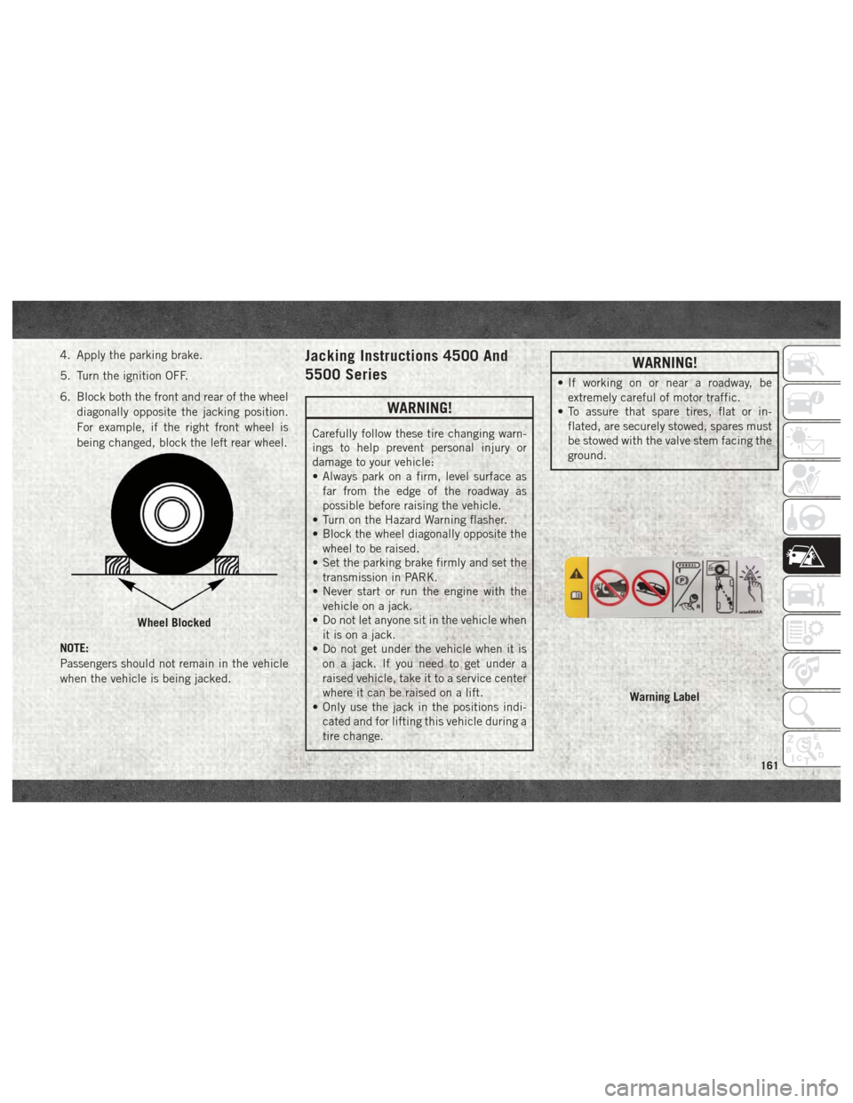
6. Block both the front and rear of the wheeldiagonally opposite the jacking position.
For example, if the right front wheel is
being changed, block the left rear wheel.
NOTE:
Passengers should not remain in the vehicle
when the vehicle is being jacked.Jacking Instructions 4500 And
5500 Series
WARNING!
Carefully follow these tire changing warn-
ings to help prevent personal injury or
damage to your vehicle:
• Always park on a firm, level surface as far from the edge of the roadway as
possible before raising the vehicle.
• Turn on the Hazard Warning flasher.
• Block the wheel diagonally opposite the
wheel to be raised.
• Set the parking brake firmly and set the
transmission in PARK.
• Never start or run the engine with the
vehicle on a jack.
• Do not let anyone sit in the vehicle when
it is on a jack.
• Do not get under the vehicle when it is
on a jack. If you need to get under a
raised vehicle, take it to a service center
where it can be raised on a lift.
• Only use the jack in the positions indi-
cated and for lifting this vehicle during a
tire change.
WARNING!
• If working on or near a roadway, beextremely careful of motor traffic.
• To assure that spare tires, flat or in-
flated, are securely stowed, spares must
be stowed with the valve stem facing the
ground.
Wheel Blocked
Warning Label
161
Page 164 of 298
CAUTION!
Do not attempt to raise the vehicle by
jacking on locations other than those indi-
cated in the Jacking Instructions for this
vehicle.
1. If equipped, remove the spare wheel, jack, and tools from storage.
2. Using the lug wrench, loosen, but do not remove, the lug nuts by turning them
counterclockwise one turn while the
wheel is still on the ground.
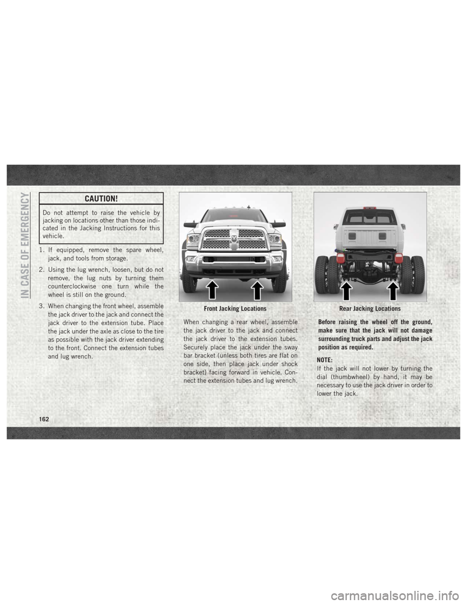
3. When changing the front wheel, assemble the jack driver to the jack and connect the
jack driver to the extension tube. Place
the jack under the axle as close to the tire
as possible with the jack driver extending
to the front. Connect the extension tubes
and lug wrench. When changing a rear wheel, assemble
the jack driver to the jack and connect
the jack driver to the extension tubes.
Securely place the jack under the sway
bar bracket (unless both tires are flat on
one side, then place jack under shock
bracket) facing forward in vehicle. Con-
nect the extension tubes and lug wrench.Before raising the wheel off the ground,
make sure that the jack will not damage
surrounding truck parts and adjust the jack
position as required.
NOTE:
If the jack will not lower by turning the
dial (thumbwheel) by hand, it may be
necessary to use the jack driver in order to
lower the jack.
Front Jacking LocationsRear Jacking Locations
IN CASE OF EMERGENCY
162
Page 170 of 298

6. Move the gear selector to the NEUTRALposition.
7. The vehicle may then be started in NEUTRAL.
FREEING A STUCK VEHICLE
If your vehicle becomes stuck in mud, sand,
or snow, it can often be moved using a rock-
ing motion. Turn the steering wheel right and
left to clear the area around the front wheels.
Next, shift back and forth between DRIVE
and REVERSE (with automatic transmission)
or SECOND GEAR and REVERSE (with
manual transmission) while gently pressing
the accelerator. Use the least amount of ac-
celerator pedal pressure that will maintain
the rocking motion, without spinning the
wheels or racing the engine. NOTE:
Push the "ESC Off" switch, to place the Elec-
tronic Stability Control (ESC) system in "Par-
tial Off" mode, before rocking the vehicle.
Refer to “Electronic Brake Control System”
in “Safety” in the Owner’s Manual at
www.mopar.com/en-us/care/owners-manual.html
(U.S. Residents) or www.owners.mopar.ca
(Canadian Residents) for further information.
Once the vehicle has been freed, push the
"ESC Off" switch again to restore "ESC On"
mode.
WARNING!
Fast spinning tires can be dangerous.
Forces generated by excessive wheel
speeds may cause damage, or even failure,
of the axle and tires. A tire could explode
and injure someone. Do not spin your
vehicle's wheels faster than 30 mph
(48 km/h) or for longer than 30 seconds
continuously without stopping when you
are stuck and do not let anyone near a
spinning wheel, no matter what the speed.
CAUTION!
• Racing the engine or spinning the
wheels may lead to transmission over-
heating and failure. Allow the engine to
idle with the transmission in NEUTRAL
for at least one minute after every five
rocking-motion cycles. This will mini-
mize overheating and reduce the risk of
clutch or transmission failure during
prolonged efforts to free a stuck vehicle.
• When “rocking” a stuck vehicle by shift-
ing between DRIVE/SECOND GEAR and
REVERSE, do not spin the wheels faster
than 15 mph (24 km/h), or drivetrain
damage may result.
• Revving the engine or spinning the
wheels too fast may lead to transmission
overheating and failure. It can also dam-
age the tires. Do not spin the wheels
above 30 mph (48 km/h) while in gear
(no transmission shifting occurring).
IN CASE OF EMERGENCY
168
Page 175 of 298
SERVICING AND MAINTENANCE
SCHEDULED SERVICING — GASOLINE
ENGINE................... .174
Maintenance Plan – Gasoline Engine . .175
Heavy Duty Use Of The Vehicle ......178
SCHEDULED MAINTENANCE —
6.7L CUMMINS DIESEL ENGINE.....178
Oil Change Indicator System — Cummins
Diesel.....................178
Perform Service Indicator — Cummins
Diesel .....................179
Maintenance Plan — Cummins Diesel
Engine .....................180
ENGINE COMPARTMENT .........184
6.4L Engine.................184
6.7L Diesel Engine — Six-Speed
AS69RC HD (3500/Chassis Cab
Models) ....................185
DEALER SERVICE —
6.7L DIESEL ENGINE ............186
Engine Air Cleaner Filter .........186
Draining Fuel/Water Separator Filter . .187
Engine Mounted Fuel Filter
Replacement .................188
Underbody Mounted Fuel Filter
Replacement .................189
Priming If The Engine Has Run Out
Of Fuel ....................190
HOISTING ................. .191
TIRES .................... .191
Tire Safety Information..........191
Tires — General Information .......199
Tire Types ...................203
Spare Tires — If Equipped .........204
Wheel And Wheel Trim Care .......206
DEPARTMENT OF TRANSPORTATION
UNIFORM TIRE QUALITY GRADES . . . .207
Treadwear...................207
Traction Grades ...............207
Temperature Grades .............208
SERVICING AND MAINTENANCE
173
Page 177 of 298
Maintenance Plan –
Gasoline Engine
Required Maintenance
Refer to the maintenance plan on the follow-
ing pages for required maintenance.
At Every Oil Change Interval As Indicated By OilChange Indicator System:
• Change oil and filter.
• Rotate the tires. Rotate at the first sign of
irregular wear, even if it occurs before the oil
indicator system turns on.
• Inspect engine cooling system protection and hoses.
• Inspect exhaust system.
• Inspect engine air cleaner if using in dusty or off-road conditions.
• Inspect battery and clean and tighten ter- minals as required.
• Inspect automatic transmission fluid if equipped with dipstick.
• Inspect brake pads, shoes, rotors, drums, hoses and park brake.
• Inspect front end, and lubricate — If equipped with serviceable fittings.
At Every Oil Change Interval As Indicated By Oil Change Indicator System:
• Lube the front drive shaft fitting (4X4 models only).
175
Page 182 of 298
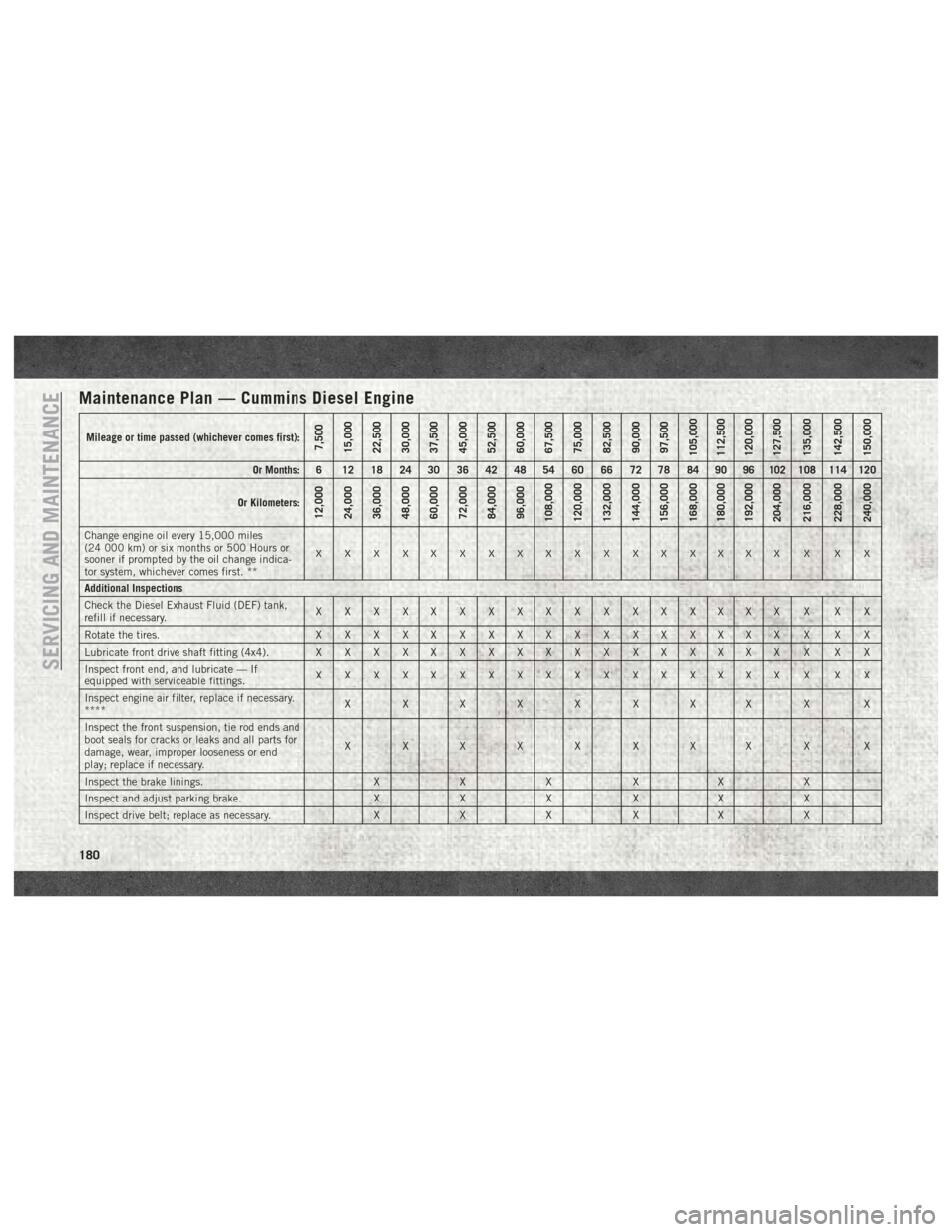
Maintenance Plan — Cummins Diesel Engine
Mileage or time passed (whichever comes first):7,500
15,000
22,500
30,000
37,500
45,000
52,500
60,000
67,500
75,000
82,500
90,000
97,500
105,000
112,500
120,000
127,500
135,000
142,500
150,000
Or Months: 6 12 18 24 30 36 42 48 54 60 66 72 78 84 90 96 102 108 114 120
Or Kilometers:
12,000
24,000
36,000
48,000
60,000
72,000
84,000
96,000
108,000
120,000
132,000
144,000
156,000
168,000
180,000
192,000
204,000
216,000
228,000
240,000
Change engine oil every 15,000 miles
(24 000 km) or six months or 500 Hours or
sooner if prompted by the oil change indica-
tor system, whichever comes first. ** XXXXXXXXXXXXXXXXX X XX
Additional Inspections
Check the Diesel Exhaust Fluid (DEF) tank,
refill if necessary. XXXXXXXXXXXXXXXXX X XX
Rotate the tires. X X X X X X X XXXXXXXXXX X XX
Lubricate front drive shaft fitting (4x4). X X X X X X X XXXXXXXXXX X XX
Inspect front end, and lubricate — If
equipped with serviceable fittings. XXXXXXXXXXXXXXXXX X XX
Inspect engine air filter, replace if necessary.
**** XX XX X X XX X X
Inspect the front suspension, tie rod ends and
boot seals for cracks or leaks and all parts for
damage, wear, improper looseness or end
play; replace if necessary. XX XX X X XX X X
Inspect the brake linings. XXX XX X
Inspect and adjust parking brake. XXX XX X
Inspect drive belt; replace as necessary. XXX XX X
SERVICING AND MAINTENANCE
180
Page 193 of 298
HOISTING
A conventional floor jack may be used at the
jacking locations. Refer to the graphics that
show jacking locations. However, a floor jack
or frame hoist must never be used on any
other parts of the underbody.
CAUTION!
Never use a floor jack directly under the
differential housing of a loaded truck or
damage to your vehicle may result.
TIRES
Tire Safety Information
Tire safety information will cover aspects of
the following information: Tire Markings, Tire
Identification Numbers, Tire Terminology and
Definitions, Tire Pressures, and Tire Loading.
Tire MarkingsNOTE:
• P (Passenger) — Metric tire sizing is basedon U.S. design standards. P-Metric tires
have the letter “P” molded into the sidewall
preceding the size designation. Example:
P215/65R15 95H.
• European — Metric tire sizing is based on European design standards. Tires designed
to this standard have the tire size molded
into the sidewall beginning with the section
width. The letter "P" is absent from this tire
size designation. Example: 215/
65R15 96H.
• LT (Light Truck) — Metric tire sizing is based on U.S. design standards. The size
designation for LT-Metric tires is the same
as for P-Metric tires except for the letters
“LT” that are molded into the sidewall pre-
ceding the size designation. Example:
LT235/85R16.
• Temporary spare tires are designed for tem- porary emergency use only. Temporary high
pressure compact spare tires have the letter
“T” or “S” molded into the sidewall preced-
ing the size designation. Example: T145/
80D18 103M.
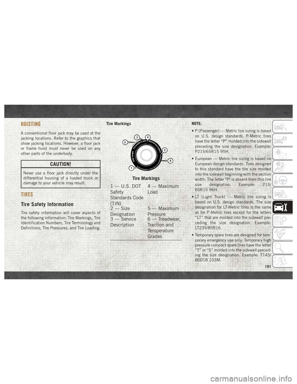
Tire Markings
1 — U.S. DOT
Safety
Standards Code
(TIN) 4 — Maximum
Load
2 — Size
Designation 5 — Maximum
Pressure
3 — Service
Description 6 — Treadwear,
Traction and
Temperature
Grades
191
Page 196 of 298

Tire Identification Number (TIN)
The TIN may be found on one or both sides of
the tire; however, the date code may only be
on one side. Tires with white sidewalls will
have the full TIN, including the date code,located on the white sidewall side of the tire.
Look for the TIN on the outboard side of black
sidewall tires as mounted on the vehicle. If
the TIN is not found on the outboard side,
then you will find it on the inboard side of the
tire.
EXAMPLE:
DOT MA L9 ABCD 0301
DOT = Department of Transportation
• This symbol certifies that the tire is in compliance with the U.S. Department of Transportation tire safety standards and is approved for highway
use
MA = Code representing the tire manufacturing location (two digits)
L9 = Code representing the tire size (two digits)
ABCD = Code used by the tire manufacturer (one to four digits)
03 = Number representing the week in which the tire was manufactured (two digits)
• 03 means the 3rd week
01 = Number representing the year in which the tire was manufactured (two digits)
• 01 means the year 2001
• Prior to July 2000, tire manufacturers were only required to have one number to represent the year in which the tire was manufactured. Example:
031 could represent the 3rd week of 1981 or 1991
SERVICING AND MAINTENANCE
194
Page 198 of 298

Tire Loading And Tire Pressure
NOTE:
The proper cold tire inflation pressure is
listed on the driver’s side B-Pillar or the rear
edge of the driver's side door.
Check the inflation pressure of each tire,
including the spare tire (if equipped), at least
monthly and inflate to the recommended
pressure for your vehicle.Tire And Loading Information Placard This placard tells you important information
about the:
1. Number of people that can be carried in
the vehicle.
2. Total weight your vehicle can carry.
3. Tire size designed for your vehicle.
4. Cold tire inflation pressures for the front, rear, and spare tires.
Loading
The vehicle maximum load on the tire must
not exceed the load carrying capacity of the
tire on your vehicle. You will not exceed the
tire's load carrying capacity if you adhere to
the loading conditions, tire size, and cold tire
inflation pressures specified on the Tire and
Loading Information placard in “Vehicle
Loading” in the “Starting And Operating”
section of this manual.
NOTE:
Under a maximum loaded vehicle condition,
gross axle weight ratings (GAWRs) for the
front and rear axles must not be exceeded.
Example Tire Placard Location (Door)
Example Tire Placard Location (B-Pillar)
Tire And Loading Information Placard
SERVICING AND MAINTENANCE
196