light Ram 4500 Chassis Cab 2018 Repair Manual
[x] Cancel search | Manufacturer: RAM, Model Year: 2018, Model line: 4500 Chassis Cab, Model: Ram 4500 Chassis Cab 2018Pages: 298, PDF Size: 5.88 MB
Page 159 of 298
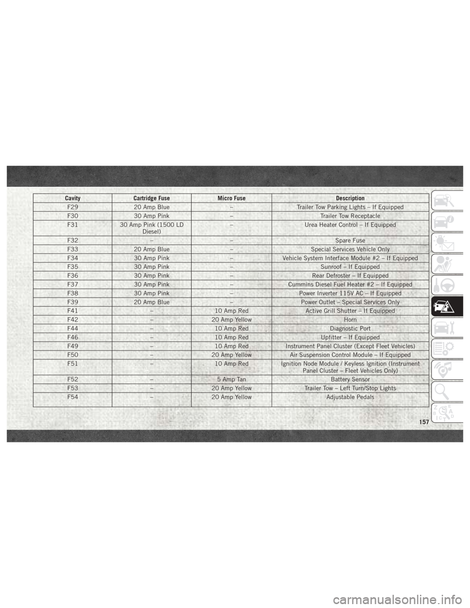
CavityCartridge Fuse Micro Fuse Description
F29 20 Amp Blue –Trailer Tow Parking Lights – If Equipped
F30 30 Amp Pink –Trailer Tow Receptacle
F31 30 Amp Pink (1500 LD
Diesel) –
Urea Heater Control – If Equipped
F32 –– Spare Fuse
F33 20 Amp Blue –Special Services Vehicle Only
F34 30 Amp Pink –Vehicle System Interface Module #2 – If Equipped
F35 30 Amp Pink –Sunroof – If Equipped
F36 30 Amp Pink –Rear Defroster – If Equipped
F37 30 Amp Pink –Cummins Diesel Fuel Heater #2 – If Equipped
F38 30 Amp Pink –Power Inverter 115V AC – If Equipped
F39 20 Amp Blue –Power Outlet – Special Services Only
F41 –10 Amp Red Active Grill Shutter – If Equipped
F42 –20 Amp Yellow Horn
F44 –10 Amp Red Diagnostic Port
F46 –10 Amp Red Upfitter – If Equipped
F49 –10 Amp Red Instrument Panel Cluster (Except Fleet Vehicles)
F50 –20 Amp Yellow Air Suspension Control Module – If Equipped
F51 –10 Amp Red Ignition Node Module / Keyless Ignition (Instrument
Panel Cluster – Fleet Vehicles Only)
F52 –5 Amp Tan Battery Sensor
F53 –20 Amp Yellow Trailer Tow – Left Turn/Stop Lights
F54 –20 Amp Yellow Adjustable Pedals
157
Page 161 of 298

CavityCartridge Fuse Micro Fuse Description
F78 –10 Amp Red Engine Control Module / Electric Power Steering
F79 –15 Amp Blue Clearance Lights
F80 –10 Amp Red Universal Garage Door Opener / Compass
F81 –20 Amp Yellow Trailer Tow Right Turn / Stop Lights
F82 –10 Amp Red Steering Column Control Module / Cruise Control
F84 –15 Amp Blue Switch Bank / Instrument Cluster
F85 –10 Amp Red Airbag Module
F86 –10 Amp Red Airbag Module
F87 –10 Amp Red Air Suspension – If Equipped / Trailer Tow / Steering Col-
umn Control Module
F88 –15 Amp Blue Instrument Panel Cluster
F90/F91 –20 Amp Yellow Power Outlet (Rear Seats) Customer Selectable
F93 –20 Amp Yellow Cigar Lighter
F94 –10 Amp Red Shifter / Transfer Case Module
F95 –10 Amp Red Rear Camera / Park Assist
F96 –10 Amp Red Rear Seat Heater Switch
F97 –25 Amp Clear Rear Heated Seats & Heated Steering Wheel – If
Equipped
F98 –25 Amp Clear Front Heated Seats – If Equipped
F99 –10 Amp Red Climate Control
F100 –10 Amp Red Upfitters – If Equipped
F101 –15 Amp Blue Electrochromatic Mirror / Smart High Beams – If
Equipped
F104 –20 Amp Yellow Power Outlets (Instrument Panel / Center Console)
159
Page 165 of 298
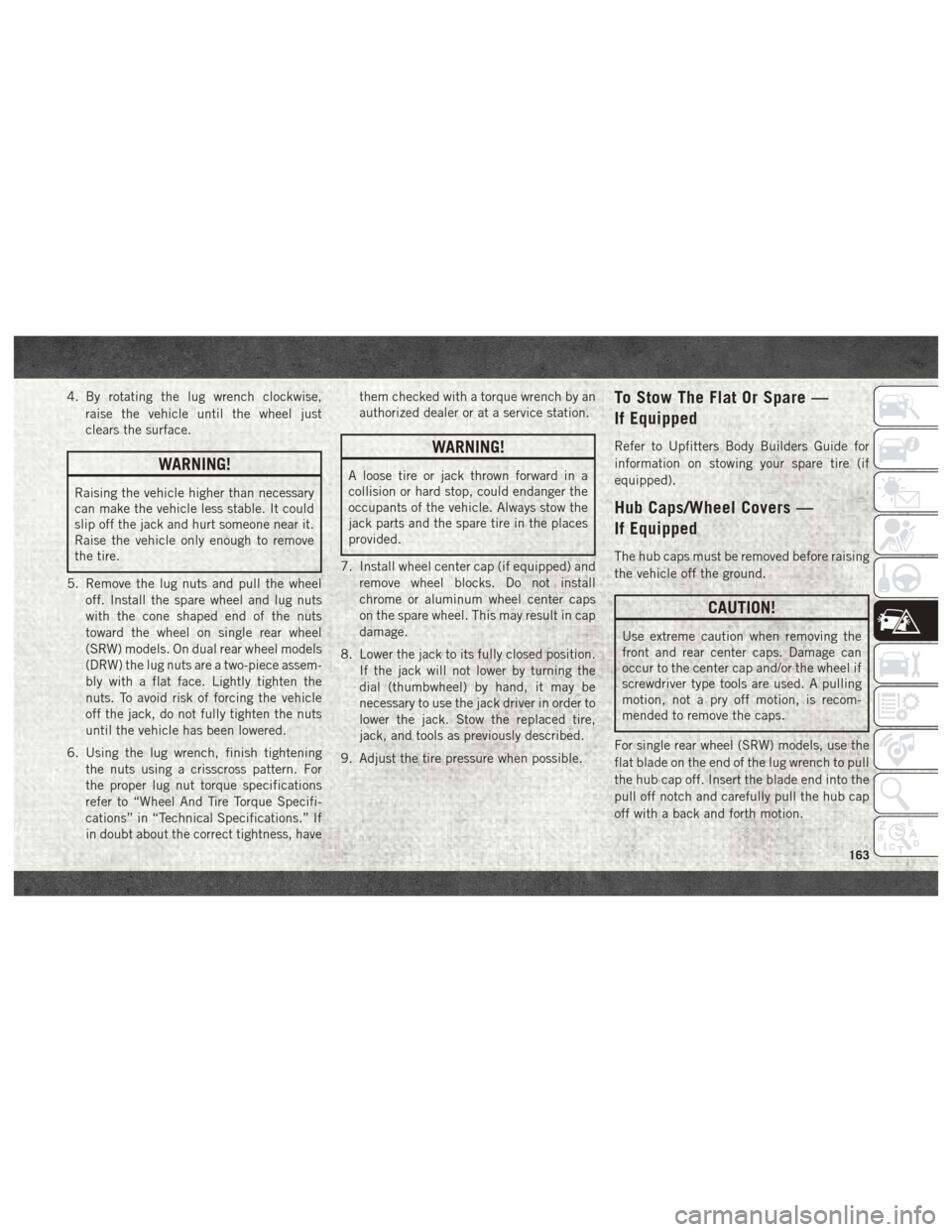
4. By rotating the lug wrench clockwise,raise the vehicle until the wheel just
clears the surface.
WARNING!
Raising the vehicle higher than necessary
can make the vehicle less stable. It could
slip off the jack and hurt someone near it.
Raise the vehicle only enough to remove
the tire.
5. Remove the lug nuts and pull the wheel off. Install the spare wheel and lug nuts
with the cone shaped end of the nuts
toward the wheel on single rear wheel
(SRW) models. On dual rear wheel models
(DRW) the lug nuts are a two-piece assem-
bly with a flat face. Lightly tighten the
nuts. To avoid risk of forcing the vehicle
off the jack, do not fully tighten the nuts
until the vehicle has been lowered.
6. Using the lug wrench, finish tightening the nuts using a crisscross pattern. For
the proper lug nut torque specifications
refer to “Wheel And Tire Torque Specifi-
cations” in “Technical Specifications.” If
in doubt about the correct tightness, have them checked with a torque wrench by an
authorized dealer or at a service station.
WARNING!
A loose tire or jack thrown forward in a
collision or hard stop, could endanger the
occupants of the vehicle. Always stow the
jack parts and the spare tire in the places
provided.
7. Install wheel center cap (if equipped) and remove wheel blocks. Do not install
chrome or aluminum wheel center caps
on the spare wheel. This may result in cap
damage.
8. Lower the jack to its fully closed position. If the jack will not lower by turning the
dial (thumbwheel) by hand, it may be
necessary to use the jack driver in order to
lower the jack. Stow the replaced tire,
jack, and tools as previously described.
9. Adjust the tire pressure when possible.
To Stow The Flat Or Spare —
If Equipped
Refer to Upfitters Body Builders Guide for
information on stowing your spare tire (if
equipped).
Hub Caps/Wheel Covers —
If Equipped
The hub caps must be removed before raising
the vehicle off the ground.
CAUTION!
Use extreme caution when removing the
front and rear center caps. Damage can
occur to the center cap and/or the wheel if
screwdriver type tools are used. A pulling
motion, not a pry off motion, is recom-
mended to remove the caps.
For single rear wheel (SRW) models, use the
flat blade on the end of the lug wrench to pull
the hub cap off. Insert the blade end into the
pull off notch and carefully pull the hub cap
off with a back and forth motion.
163
Page 166 of 298

On 3500 models with dual rear wheels
(DRW), you must first remove the hub caps.
The jack handle driver has a hook at one end
that will fit in the pull off notch of the rear
hub caps. Position the hook and pull straight
out on the ratchet firmly. The hub cap should
pop off. The wheel skins can now be re-
moved. For the front hub cap, use the flat
blade on the end of the lug wrench to pull the
caps off. The wheel skin can now be removed.
CAUTION!
• Use a pulling motion to remove the hubcap. Do not use a twisting motion when
removing the hub cap, damage to the
hub cap; finish may occur.
• The rear hub caps on the dual rear wheel
has two pull off notches. Make sure that
the hook of the jack handle driver is
located squarely in the cap notch before
attempting to pull off.
You must use the flat end of the lug wrench to
pull off the wheel skins. Locate the hub cap
pull notches (2 notches on each cap). Insert the flat tip completely and using a back and
forth motion, loosen the wheel skin. Repeat
this procedure around the tire until the skin
pops off.
Replace the wheel skins first using a rubber
mallet. When replacing the hub caps, tilt the
cap retainer over the lug nut bolt circle and
strike the high side down with a rubber mal-
let. Be sure that the hub caps and wheel
skins are firmly seated around the wheel.
JUMP STARTING
If your vehicle has a discharged battery, it can
be jump started using a set of jumper cables
and a battery in another vehicle, or by using a
portable battery booster pack. Jump starting
can be dangerous if done improperly, so
please follow the procedures in this section
carefully.
WARNING!
Do not attempt jump starting if the battery
is frozen. It could rupture or explode and
cause personal injury.
CAUTION!
Do not use a portable battery booster pack
or any other booster source with a system
voltage greater than 12 Volts or damage to
the battery, starter motor, alternator or
electrical system may occur.
NOTE:
When using a portable battery booster pack,
follow the manufacturer's operating instruc-
tions and precautions.
Preparations For Jump Start
The battery in your vehicle is located in the
front of the engine compartment, behind the
left headlight assembly.
IN CASE OF EMERGENCY
164
Page 176 of 298
SCHEDULED SERVICING — GASOLINE
ENGINE
Your vehicle is equipped with an automatic
oil change indicator system. The oil change
indicator system will remind you that it is
time to take your vehicle in for scheduled
maintenance.
Based on engine operation conditions, the oil
change indicator message will illuminate.
This means that service is required for your
vehicle. Operating conditions such as fre-
quent short-trips, trailer tow, extremely hot or
cold ambient temperatures, and E85 fuel
usage will influence when the “Oil Change
Required” message is displayed. Severe Op-
erating Conditions can cause the change oil
message to illuminate as early as
3,500 miles (5,600 km) since last reset.
Have your vehicle serviced as soon as pos-
sible, within the next 500 miles (805 km).
Your authorized dealer will reset the oil
change indicator message after completing
the scheduled oil change. If a scheduled oil
change is performed by someone other than
your authorized dealer, the message can bereset by referring to the steps described under
“Warning And Indicator Lights” or “Instru-
ment Cluster Display” in “Getting To Know
Your Instrument Panel” in your Owner’s
Manual at
www.mopar.com/en-us/care/
owner-manual.html (U.S. Residents) or
www.owners.mopar.ca (Canadian Residents)
for further information.
Gasoline Engines:
Under no circumstances should oil change
intervals exceed 8,000 miles (13,000 km),
twelve months or 350 hours of engine run
time, whichever comes first. The 350 hours
of engine run or idle time is generally only a
concern for fleet customers.
Severe Duty:
Change Engine Oil at 4,000 miles
(6,500 km) or 350 hours of engine run time
if the vehicle is operated in a dusty and off
road environment or is operated predomi-
nately at idle or very low engine RPM’s. This
type of vehicle use is considered Severe Duty. Once A Month Or Before A Long Trip:
• Check engine oil level
• Check windshield washer fluid level
• Check the tire inflation pressures and look
for unusual wear or damage
• Check the fluid levels of the coolant reser- voir, brake master cylinder, power steering
and automatic transmission, and fill as
needed
• Check function of all interior and exterior lights
SERVICING AND MAINTENANCE
174
Page 189 of 298
If the vehicle experiences a sudden loss of
engine power while being driven in heavy
snow or rain, or when plowing snow, and/or
the “SERVICE AIR FILTER” message is dis-
played on the instrument cluster along with a
chime that repeats every 60 seconds, visually
inspect the air filter for snow/ice build up or
extreme water saturation. If the air filter is
not damaged, remove all snow/ice and rein-
stall air filter. If the air filter is damaged,
replace filter element.
NOTE:
The air filter housing contains a Mass Air
Flow sensor. This sensor is critical to proper
engine operation and component longevity.
Any damage or modification to this sensor
could result in major engine and/or exhaust
aftertreatment damage. We recommend you
use Mopar brand parts.
Even though your vehicle is equipped with an
Air Filter Monitor, a visual inspection of the
air cleaner filter element is recommended
every 15,000 miles (24,000km) or
12 months – whichever occurs first.Under nocircumstances should the air cleaner filter ele-
ment exceed 30,000 miles (48,000 km) or
24 months, whichever comes first.
CAUTION!
Many aftermarket performance air filter
elements do not adequately filter the air
entering the engine. Use of such filters can
severely damage your engine.
Draining Fuel/Water Separator
Filter
There are two fuel filter assemblies. One is
located on the driver's side of the engine. The
best access to this water drain valve is from
under the hood. The second one is on the
under body, located in front of the rear axle
above the drive shaft on pick-up models. The
Chassis Cab models second filter location is
on the frame behind the front axle. The best
access to this water drain valve is from under
the vehicle.
CAUTION!
• Do not drain the fuel/water separator
filter when the engine is running.
• Diesel fuel will damage blacktop paving
surfaces. Drain the filter into an appro-
priate container.
If water is detected in the water separator
while the engine is running, or while the
ignition switch is in the ON position, the
“Water In Fuel Indicator Light” will illumi-
nate and an audible chime will be heard five
times. At this point you should stop the
engine and drain the water from both of the
filters.
CAUTION!
If the “Water In Fuel Indicator Light” re-
mains on, DO NOT START the engine be-
fore you drain water from the fuel filters to
avoid engine damage.
If the “Water In Fuel Indicator Light” comes
on and a single chime is heard while you are
driving, or with the ignition switch in the ON
187
Page 190 of 298
position, there may be a problem with your
water separator wiring or sensor. See your
authorized dealer for service.
Upon proper draining of the water from both
fuel filters, the “Water In Fuel Indicator
Light” will remain illuminated for approxi-
mately 10 seconds. If the water was drained
while the engine was running, the “Water In
Fuel Indicator Light” may remain on for ap-
proximately three minutes.
NOTE:
Care should be taken in disposing of used
fluids from your vehicle. Used fluids, indis-
criminately discarded, can present a problem
to the environment. Contact an authorized
dealer, service station, or government agency
for advice on recycling programs and for
where used fluids and filters can be properly
disposed of in your area.
Drain the fuel/water separator filters when
the “Water In Fuel Indicator Light” is ON.
Within 10 minutes of vehicle shutdown, turn
the engine mounted filter drain valve (located
on the side of the filter assembly) counter-
clockwise 1/4 turn, and turn the under body
mounted filter drain valve (located on thebottom of the filter assembly) counterclock
wise 1 full turn. Then turn the ignition switch
to the ON position, and allow any accumu-
lated water to drain. Leave the drain valve
open until all water and contaminants have
been removed. When clean fuel is visible,
close the drain valves by turning them fully
clockwise, and turn the ignition switch to
OFF.
If more than a couple ounces/milliliters of
fuel have been drained, follow the directions
for “Priming If The Engine Has Run Out Of
Fuel.”
Engine Mounted Fuel Filter
Replacement
NOTE:
• Using a fuel filter that does not meet the
manufacturer's filtration and water separat-
ing requirements can severely impact fuel
system life and reliability.
• The engine mounted filter housing is equipped with a No-Filter-No-Run (NFNR)
feature. Engine will not run if:
1. No filter is installed. 2. Inferior/Non-approved filter is used.
Use of OEM filter is required to ensure
vehicle will run.
CAUTION!
• Diesel fuel will damage blacktop pavingsurfaces. Drain the filter into an appro-
priate container.
• Do not prefill the fuel filter when install-
ing a new fuel filter. There is a possibility
debris could be introduced into the fuel
filter during this action. It is best to
install the filter dry and allow the in-tank
lift pump to prime the fuel system.
1. Ensure engine is turned off.
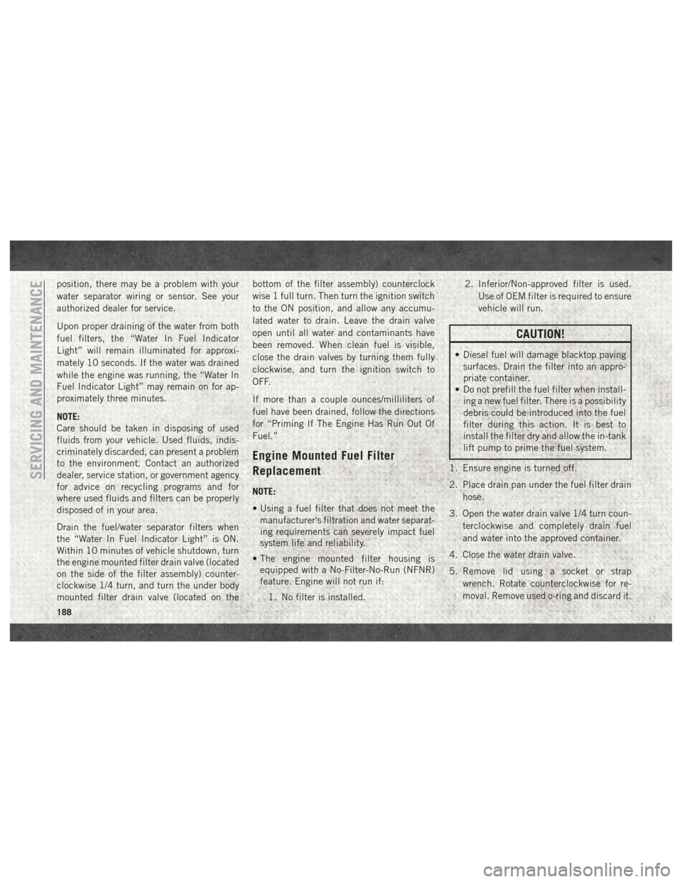
2. Place drain pan under the fuel filter drain hose.
3. Open the water drain valve 1/4 turn coun- terclockwise and completely drain fuel
and water into the approved container.
4. Close the water drain valve.
5. Remove lid using a socket or strap wrench. Rotate counterclockwise for re-
moval. Remove used o-ring and discard it.
SERVICING AND MAINTENANCE
188
Page 193 of 298
HOISTING
A conventional floor jack may be used at the
jacking locations. Refer to the graphics that
show jacking locations. However, a floor jack
or frame hoist must never be used on any
other parts of the underbody.
CAUTION!
Never use a floor jack directly under the
differential housing of a loaded truck or
damage to your vehicle may result.
TIRES
Tire Safety Information
Tire safety information will cover aspects of
the following information: Tire Markings, Tire
Identification Numbers, Tire Terminology and
Definitions, Tire Pressures, and Tire Loading.
Tire MarkingsNOTE:
• P (Passenger) — Metric tire sizing is basedon U.S. design standards. P-Metric tires
have the letter “P” molded into the sidewall
preceding the size designation. Example:
P215/65R15 95H.
• European — Metric tire sizing is based on European design standards. Tires designed
to this standard have the tire size molded
into the sidewall beginning with the section
width. The letter "P" is absent from this tire
size designation. Example: 215/
65R15 96H.
• LT (Light Truck) — Metric tire sizing is based on U.S. design standards. The size
designation for LT-Metric tires is the same
as for P-Metric tires except for the letters
“LT” that are molded into the sidewall pre-
ceding the size designation. Example:
LT235/85R16.
• Temporary spare tires are designed for tem- porary emergency use only. Temporary high
pressure compact spare tires have the letter
“T” or “S” molded into the sidewall preced-
ing the size designation. Example: T145/
80D18 103M.
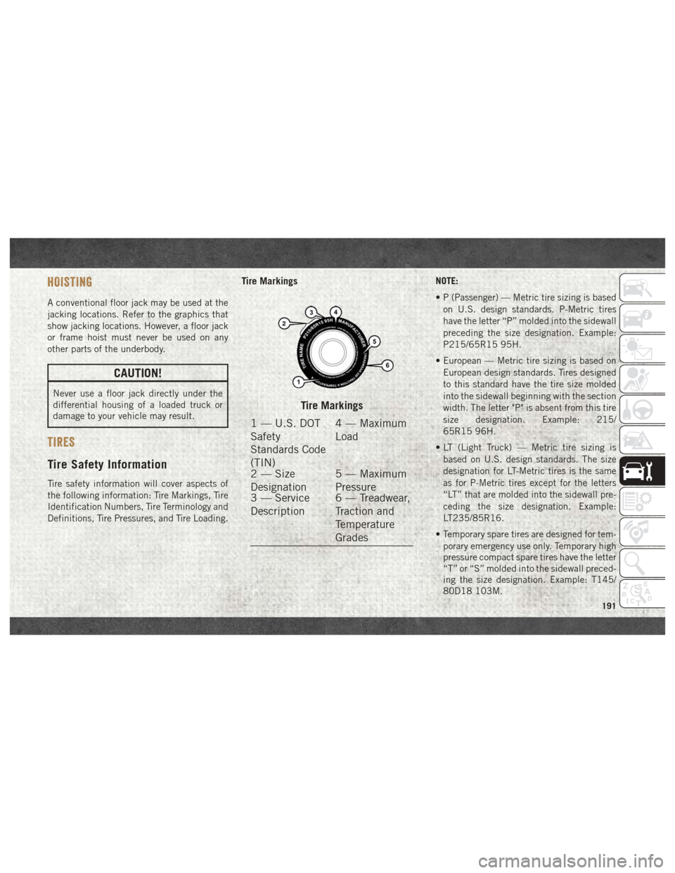
Tire Markings
1 — U.S. DOT
Safety
Standards Code
(TIN) 4 — Maximum
Load
2 — Size
Designation 5 — Maximum
Pressure
3 — Service
Description 6 — Treadwear,
Traction and
Temperature
Grades
191
Page 194 of 298
• High flotation tire sizing is based on U.S.design standards and it begins with the tire
diameter molded into the sidewall. Ex-
ample: 31x10.5 R15 LT.
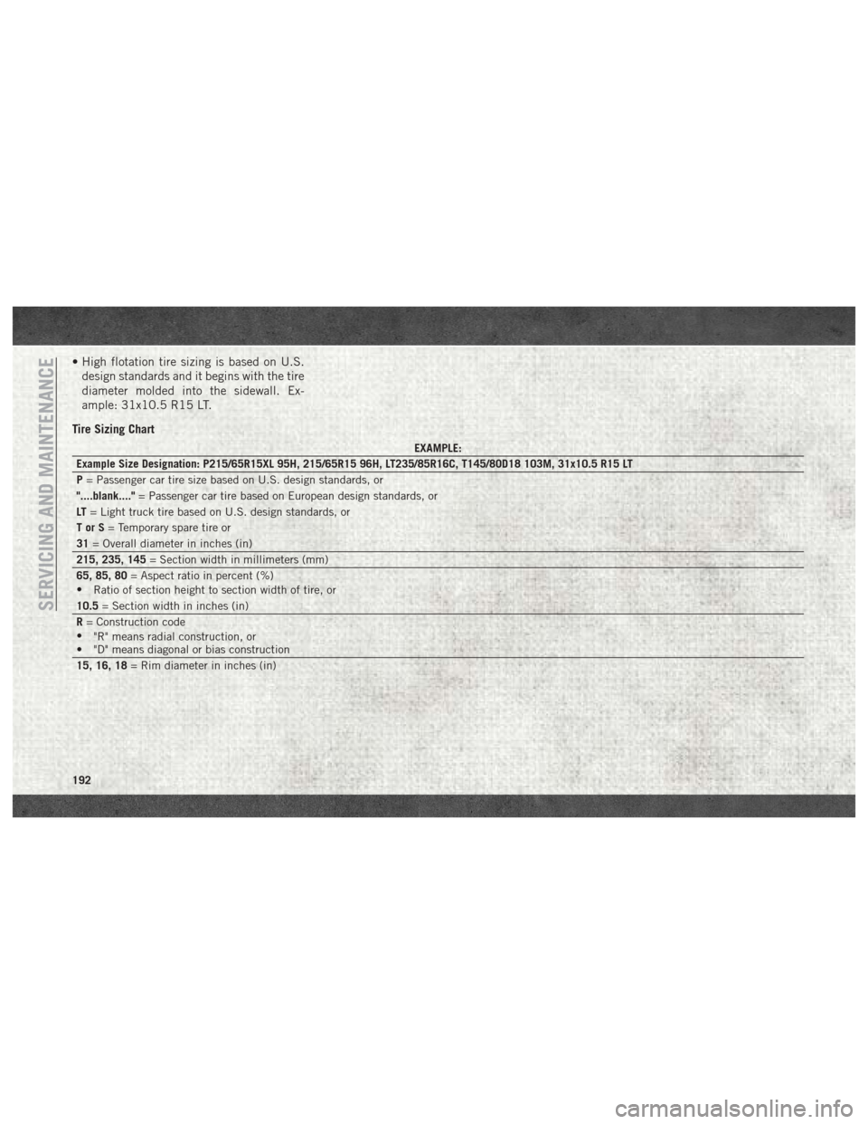
Tire Sizing Chart
EXAMPLE:
Example Size Designation: P215/65R15XL 95H, 215/65R15 96H, LT235/85R16C, T145/80D18 103M, 31x10.5 R15 LT
P = Passenger car tire size based on U.S. design standards, or
"....blank...." = Passenger car tire based on European design standards, or
LT = Light truck tire based on U.S. design standards, or
TorS= Temporary spare tire or
31 = Overall diameter in inches (in)
215, 235, 145 = Section width in millimeters (mm)
65, 85, 80 = Aspect ratio in percent (%)
• Ratio of section height to section width of tire, or
10.5 = Section width in inches (in)
R = Construction code
• "R" means radial construction, or
• "D" means diagonal or bias construction
15, 16, 18 = Rim diameter in inches (in)
SERVICING AND MAINTENANCE
192
Page 195 of 298
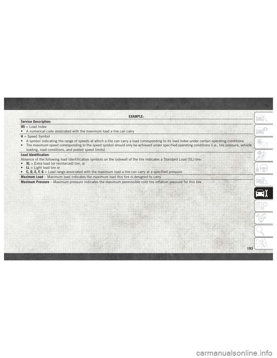
EXAMPLE:
Service Description:
95 = Load Index
• A numerical code associated with the maximum load a tire can carry
H = Speed Symbol
• A symbol indicating the range of speeds at which a tire can carry a load corresponding to its load index under certain operating conditions
• The maximum speed corresponding to the speed symbol should only be achieved under specified operating conditions (i.e., tire pressure, vehicle
loading, road conditions, and posted speed limits)
Load Identification:
Absence of the following load identification symbols on the sidewall of the tire indicates a Standard Load (SL) tire:
• XL= Extra load (or reinforced) tire, or
• LL= Light load tire or
• C, D, E, F, G = Load range associated with the maximum load a tire can carry at a specified pressure
Maximum Load – Maximum load indicates the maximum load this tire is designed to carry
Maximum Pressure – Maximum pressure indicates the maximum permissible cold tire inflation pressure for this tire
193