warning Ram 4500 Chassis Cab 2018 Manual Online
[x] Cancel search | Manufacturer: RAM, Model Year: 2018, Model line: 4500 Chassis Cab, Model: Ram 4500 Chassis Cab 2018Pages: 298, PDF Size: 5.88 MB
Page 151 of 298

WARNING!
matic transmission is in PARK (or manual
transmission is in gear). The parking brake
should always be applied when the driver
is not in the vehicle.
CAUTION!
It is necessary to follow these steps to be
certain that the transfer case is fully in
NEUTRAL (N) before recreational towing
to prevent damage to internal parts.
1. Bring the vehicle to a complete stop on level ground, with the engine running.
Firmly apply the parking brake.
2. Shift the transmission to NEUTRAL.
3. Press and hold the brake pedal.
4. Depress the clutch pedal on a manual transmission.
5. Shift the transfer case into NEUTRAL: • With manual shift transfer case, shift
the transfer case lever into NEUTRAL
(N).
• With electronic shift transfer case, push and hold the transfer case NEU-
TRAL (N) button. Some models have a
small, recessed "N" button (at the cen-
ter of the transfer case switches) that
must be pressed using a ballpoint pen
or similar object. Other models have a
rectangular NEUTRAL switch, below
the rotary transfer case control knob.
The NEUTRAL (N) indicator light will
blink while the shift is in progress. The
light will stop blinking (stay on solid)
when the shift to NEUTRAL (N) is com-
plete. After the shift is completed and
the NEUTRAL (N) light stays on, re-
lease the NEUTRAL (N) button.
6. Release the parking brake.
7. Shift the transmission into REVERSE. 8. Release the brake pedal (and clutch pedal
on manual transmissions) for five seconds
and ensure that there is no vehicle
movement.
9. Repeat steps seven and eight with auto- matic transmission in DRIVE or manual
transmission in first gear.
10. Shift the transmission to NEUTRAL. Firmly apply the parking brake. Turn OFF
the engine. For vehicles with Keyless
Enter-N-Go, push and hold the ENGINE
START/STOP button until the engine
shuts off.
11. Shift the transmission into PARK or place manual transmission in gear (NOT
in NEUTRAL).
12. Place the ignition in the OFF mode, and remove the key fob.
13. Attach the vehicle to the tow vehicle using a suitable tow bar.
14. Release the parking brake.
149
Page 155 of 298
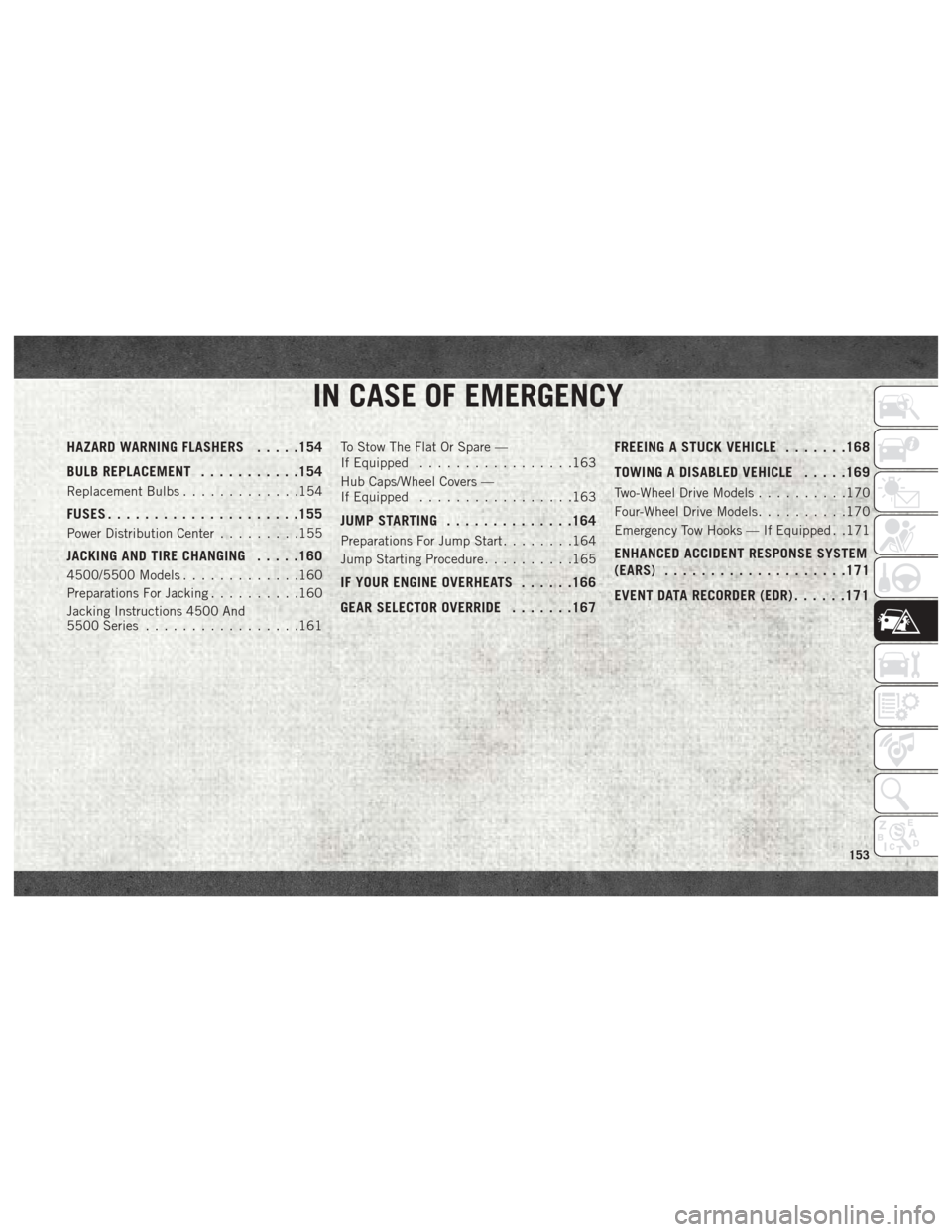
IN CASE OF EMERGENCY
HAZARD WARNING FLASHERS.....154
BULB REPLACEMENT ...........154
Replacement Bulbs.............154
FUSES.................... .155
Power Distribution Center.........155
JACKING AND TIRE CHANGING .....160
4500/5500 Models.............160
Preparations For Jacking ..........160
Jacking Instructions 4500 And
5500 Series .................161 To Stow The Flat Or Spare —
If Equipped
.................163
Hub Caps/Wheel Covers —
If Equipped .................163
JUMP STARTING ..............164
Preparations For Jump Start ........164
Jump Starting Procedure ..........165
IF YOUR ENGINE OVERHEATS ......166
GEAR SELECTOR OVERRIDE .......167FREEING A STUCK VEHICLE
.......168
TOWING A DISABLED VEHICLE .....169
Two-Wheel Drive Models..........170
Four-Wheel Drive Models ..........170
Emergency Tow Hooks — If Equipped . .171
ENHANCED ACCIDENT RESPONSE SYSTEM
(EARS) ................... .171
EVENT DATA RECORDER (EDR) ......171
IN CASE OF EMERGENCY
153
Page 156 of 298
HAZARD WARNING FLASHERS
The Hazard Warning flasher switch is located
on the upper switch bank just below the
radio.
Push the switch to turn on the Hazard Warn-
ing flasher. When the switch is activated, all
directional turn signals will flash on and off to
warn oncoming traffic of an emergency. Push
the switch a second time to turn off the
Hazard Warning flashers.
This is an emergency warning system and it
should not be used when the vehicle is in
motion. Use it when your vehicle is disabled
and it is creating a safety hazard for other
motorists.
When you must leave the vehicle to seek
assistance, the Hazard Warning flashers will
continue to operate even though the ignition
is placed in the OFF position.
NOTE:
With extended use the Hazard Warning flash-
ers may wear down your battery.
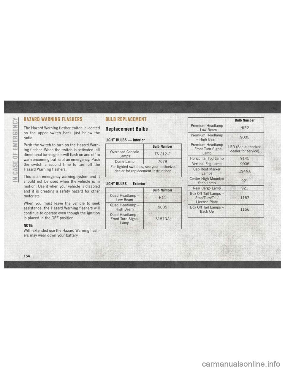
BULB REPLACEMENT
Replacement Bulbs
LIGHT BULBS — Interior
Bulb Number
Overhead Console Lamps TS 212-2
Dome Lamp 7679
For lighted switches, see your authorized dealer for replacement instructions.
LIGHT BULBS — Exterior
Bulb Number
Quad Headlamp – Low Beam H11
Quad Headlamp – High Beam 9005
Quad Headlamp – Front Turn Signal Lamp 3157NA
Bulb Number
Premium Headlamp – Low Beam HIR2
Premium Headlamp – High Beam 9005
Premium Headlamp – Front Turn Signal Lamp LED (See authorized
dealer for service)
Horizontal Fog Lamp 9145 Vertical Fog Lamp 9006
Cab Roof Marker Lamps 194NA
Center High Mounted Stop Lamp 921
Rear Cargo Lamp 921
Box Off Tail Lamps – Stop/Turn/Tail/License Plate 1157
Box Off Tail Lamps – Back Up 1156
IN CASE OF EMERGENCY
154
Page 157 of 298

FUSES
WARNING!
• When replacing a blown fuse, always usean appropriate replacement fuse with
the same amp rating as the original fuse.
Never replace a fuse with another fuse of
higher amp rating. Never replace a
blown fuse with metal wires or any other
material. Do not place a fuse inside a
circuit breaker cavity or vice versa. Fail-
ure to use proper fuses may result in
serious personal injury, fire and/or prop-
erty damage.
WARNING!
• Before replacing a fuse, make sure thatthe ignition is off and that all the other
services are switched off and/or disen-
gaged.
• If the replaced fuse blows again, contact
an authorized dealer.
• If a general protection fuse for safety
systems (air bag system, braking sys-
tem), power unit systems (engine sys-
tem, transmission system) or steering
system blows, contact an authorized
dealer.
Power Distribution Center
The Power Distribution Center is located in
the engine compartment near the battery.
This center contains cartridge fuses, micro
fuses, relays, and circuit breakers. A descrip-
tion of each fuse and component may be
stamped on the inside cover, otherwise the
cavity number of each fuse is stamped on the
inside cover that corresponds to the following
chart.
Cavity Cartridge Fuse Micro Fuse Description
F01 80 Amp Black –Rad Fan Control Module – If Equipped
F03 60 Amp Yellow –Rad Fan – If Equipped
F05 40 Amp Green –Compressor for Air Suspension – If Equipped
F06 40 Amp Green –Antilock Brakes/Electronic Stability Control Pump
F07 40 Amp Green – Starter Solenoid
F08 20 Amp Blue (1500 LD/
Cummins Diesel) –
Emissions Diesel – If Equipped
155
Page 162 of 298

CAUTION!
• When installing the power distributioncenter cover, it is important to ensure
the cover is properly positioned and fully
latched. Failure to do so may allow water
to get into the power distribution center
and possibly result in an electrical sys-
tem failure.
• When replacing a blown fuse, it is impor-
tant to use only a fuse having the correct
amperage rating. The use of a fuse with
a rating other than indicated may result
in a dangerous electrical system over-
load. If a properly rated fuse continues
to blow, it indicates a problem in the
circuit that must be corrected.
JACKING AND TIRE CHANGING
WARNING!
• Do not attempt to change a tire on theside of the vehicle close to moving traf-
fic. Pull far enough off the road to avoid
the danger of being hit when operating
the jack or changing the wheel.
• Being under a jacked-up vehicle is dan-
gerous. The vehicle could slip off the
jack and fall on you. You could be
crushed. Never put any part of your body
under a vehicle that is on a jack. If you
need to get under a raised vehicle, take
it to a service center where it can be
raised on a lift.
• Never start or run the engine while the
vehicle is on a jack.
• The jack is designed to be used as a tool
for changing tires only. The jack should
not be used to lift the vehicle for service
purposes. The vehicle should be jacked
on a firm level surface only. Avoid ice or
slippery areas.
4500/5500 Models
These vehicles do not come equipped with a
jack.
NOTE:
Jacking and tire changing on 4500/
5500 models should be performed by an
authorized dealer, or knowledgeable service
personnel with the appropriate heavy duty
equipment, like a tire service company.
Preparations For Jacking
1. Park the vehicle on a firm, level surface.
Avoid ice or slippery areas.
WARNING!
Do not attempt to change a tire on the side
of the vehicle close to moving traffic, pull
far enough off the road to avoid being hit
when operating the jack or changing the
wheel.
2. Place the gear selector into PARK. On four-wheel drive vehicles, shift the trans-
fer case to the 4L position.
3. Turn on the Hazard Warning flasher.
IN CASE OF EMERGENCY
160
Page 163 of 298
4. Apply the parking brake.
5. Turn the ignition OFF.
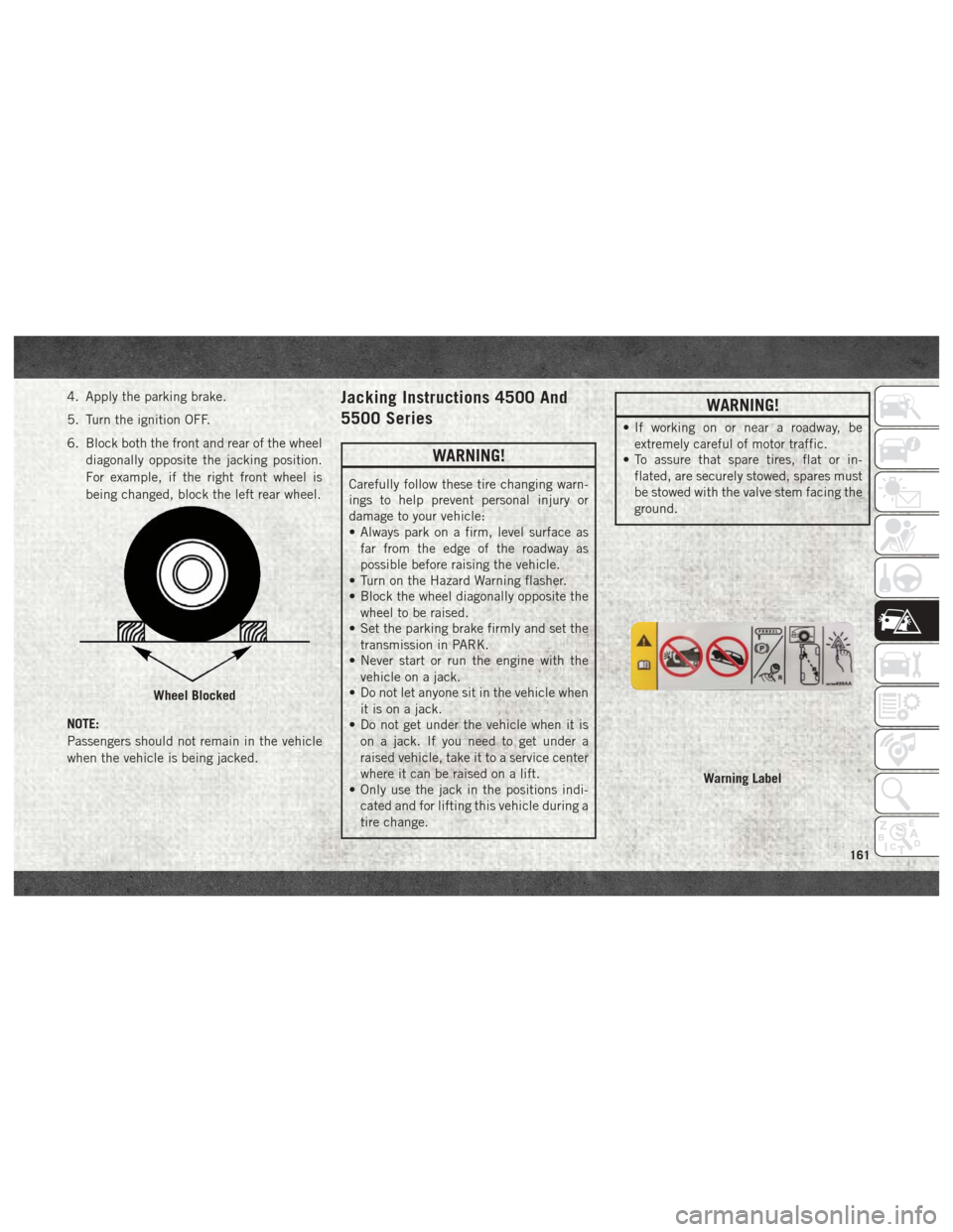
6. Block both the front and rear of the wheeldiagonally opposite the jacking position.
For example, if the right front wheel is
being changed, block the left rear wheel.
NOTE:
Passengers should not remain in the vehicle
when the vehicle is being jacked.Jacking Instructions 4500 And
5500 Series
WARNING!
Carefully follow these tire changing warn-
ings to help prevent personal injury or
damage to your vehicle:
• Always park on a firm, level surface as far from the edge of the roadway as
possible before raising the vehicle.
• Turn on the Hazard Warning flasher.
• Block the wheel diagonally opposite the
wheel to be raised.
• Set the parking brake firmly and set the
transmission in PARK.
• Never start or run the engine with the
vehicle on a jack.
• Do not let anyone sit in the vehicle when
it is on a jack.
• Do not get under the vehicle when it is
on a jack. If you need to get under a
raised vehicle, take it to a service center
where it can be raised on a lift.
• Only use the jack in the positions indi-
cated and for lifting this vehicle during a
tire change.
WARNING!
• If working on or near a roadway, beextremely careful of motor traffic.
• To assure that spare tires, flat or in-
flated, are securely stowed, spares must
be stowed with the valve stem facing the
ground.
Wheel Blocked
Warning Label
161
Page 165 of 298
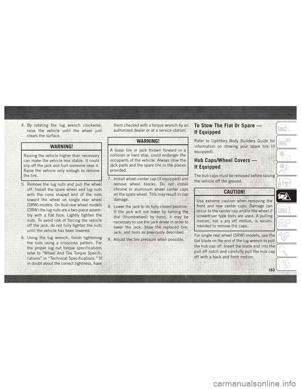
4. By rotating the lug wrench clockwise,raise the vehicle until the wheel just
clears the surface.
WARNING!
Raising the vehicle higher than necessary
can make the vehicle less stable. It could
slip off the jack and hurt someone near it.
Raise the vehicle only enough to remove
the tire.
5. Remove the lug nuts and pull the wheel off. Install the spare wheel and lug nuts
with the cone shaped end of the nuts
toward the wheel on single rear wheel
(SRW) models. On dual rear wheel models
(DRW) the lug nuts are a two-piece assem-
bly with a flat face. Lightly tighten the
nuts. To avoid risk of forcing the vehicle
off the jack, do not fully tighten the nuts
until the vehicle has been lowered.
6. Using the lug wrench, finish tightening the nuts using a crisscross pattern. For
the proper lug nut torque specifications
refer to “Wheel And Tire Torque Specifi-
cations” in “Technical Specifications.” If
in doubt about the correct tightness, have them checked with a torque wrench by an
authorized dealer or at a service station.
WARNING!
A loose tire or jack thrown forward in a
collision or hard stop, could endanger the
occupants of the vehicle. Always stow the
jack parts and the spare tire in the places
provided.
7. Install wheel center cap (if equipped) and remove wheel blocks. Do not install
chrome or aluminum wheel center caps
on the spare wheel. This may result in cap
damage.
8. Lower the jack to its fully closed position. If the jack will not lower by turning the
dial (thumbwheel) by hand, it may be
necessary to use the jack driver in order to
lower the jack. Stow the replaced tire,
jack, and tools as previously described.
9. Adjust the tire pressure when possible.
To Stow The Flat Or Spare —
If Equipped
Refer to Upfitters Body Builders Guide for
information on stowing your spare tire (if
equipped).
Hub Caps/Wheel Covers —
If Equipped
The hub caps must be removed before raising
the vehicle off the ground.
CAUTION!
Use extreme caution when removing the
front and rear center caps. Damage can
occur to the center cap and/or the wheel if
screwdriver type tools are used. A pulling
motion, not a pry off motion, is recom-
mended to remove the caps.
For single rear wheel (SRW) models, use the
flat blade on the end of the lug wrench to pull
the hub cap off. Insert the blade end into the
pull off notch and carefully pull the hub cap
off with a back and forth motion.
163
Page 166 of 298

On 3500 models with dual rear wheels
(DRW), you must first remove the hub caps.
The jack handle driver has a hook at one end
that will fit in the pull off notch of the rear
hub caps. Position the hook and pull straight
out on the ratchet firmly. The hub cap should
pop off. The wheel skins can now be re-
moved. For the front hub cap, use the flat
blade on the end of the lug wrench to pull the
caps off. The wheel skin can now be removed.
CAUTION!
• Use a pulling motion to remove the hubcap. Do not use a twisting motion when
removing the hub cap, damage to the
hub cap; finish may occur.
• The rear hub caps on the dual rear wheel
has two pull off notches. Make sure that
the hook of the jack handle driver is
located squarely in the cap notch before
attempting to pull off.
You must use the flat end of the lug wrench to
pull off the wheel skins. Locate the hub cap
pull notches (2 notches on each cap). Insert the flat tip completely and using a back and
forth motion, loosen the wheel skin. Repeat
this procedure around the tire until the skin
pops off.
Replace the wheel skins first using a rubber
mallet. When replacing the hub caps, tilt the
cap retainer over the lug nut bolt circle and
strike the high side down with a rubber mal-
let. Be sure that the hub caps and wheel
skins are firmly seated around the wheel.
JUMP STARTING
If your vehicle has a discharged battery, it can
be jump started using a set of jumper cables
and a battery in another vehicle, or by using a
portable battery booster pack. Jump starting
can be dangerous if done improperly, so
please follow the procedures in this section
carefully.
WARNING!
Do not attempt jump starting if the battery
is frozen. It could rupture or explode and
cause personal injury.
CAUTION!
Do not use a portable battery booster pack
or any other booster source with a system
voltage greater than 12 Volts or damage to
the battery, starter motor, alternator or
electrical system may occur.
NOTE:
When using a portable battery booster pack,
follow the manufacturer's operating instruc-
tions and precautions.
Preparations For Jump Start
The battery in your vehicle is located in the
front of the engine compartment, behind the
left headlight assembly.
IN CASE OF EMERGENCY
164
Page 167 of 298
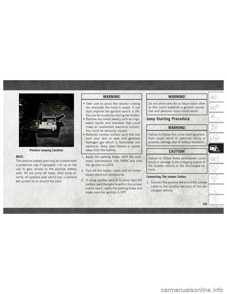
NOTE:
The positive battery post may be covered with
a protective cap if equipped. Lift up on the
cap to gain access to the positive battery
post. Do not jump off fuses. Only jump di-
rectly off positive post which has a positive
(+)symbol on or around the post.
WARNING!
• Take care to avoid the radiator cooling
fan whenever the hood is raised. It can
start anytime the ignition switch is ON.
You can be injured by moving fan blades.
• Remove any metal jewelry such as rings,
watch bands and bracelets that could
make an inadvertent electrical contact.
You could be seriously injured.
• Batteries contain sulfuric acid that can
burn your skin or eyes and generate
hydrogen gas which is flammable and
explosive. Keep open flames or sparks
away from the battery.
1. Apply the parking brake, shift the auto- matic transmission into PARK and turn
the ignition to LOCK.
2. Turn off the heater, radio, and all unnec- essary electrical accessories.
3. If using another vehicle to jump start the battery, park the vehicle within the jumper
cables reach, apply the parking brake and
make sure the ignition is OFF.
WARNING!
Do not allow vehicles to touch each other
as this could establish a ground connec-
tion and personal injury could result.
Jump Starting Procedure
WARNING!
Failure to follow this jump starting proce-
dure could result in personal injury or
property damage due to battery explosion.
CAUTION!
Failure to follow these procedures could
result in damage to the charging system of
the booster vehicle or the discharged ve-
hicle.
Connecting The Jumper Cables
1. Connect the positive (+)end of the jumper
cable to the positive (+)post of the dis-
charged vehicle.
Positive Jumping Location
165
Page 168 of 298

NOTE:
Do not jump off fuses. Only jump directly off
positive post.
2. Connect the opposite end of the positive (+) jumper cable to the positive (+)post of
the booster battery.
3. Connect the negative (-)end of the jumper
cable to the negative (-)post of the
booster battery.
4. Connect the opposite end of the negative (-)jumper cable to a good engine ground
(exposed metal part of the discharged
vehicle’s engine) away from the battery
and the fuel injection system.
WARNING!
Do not connect the jumper cable to the
negative (-) post of the discharged battery.
The resulting electrical spark could cause
the battery to explode and could result in
personal injury. Only use the specific
ground point, do not use any other exposed
metal parts. 5. Start the engine in the vehicle that has
the booster battery, let the engine idle a
few minutes, and then start the engine in
the vehicle with the discharged battery.
CAUTION!
Do not connect jumper cable to any of the
fuses on the positive battery terminal. The
resulting electrical current will blow the
fuse.
6. Once the engine is started, remove the jumper cables in the reverse sequence:
Disconnecting The Jumper Cables
1. Disconnect the negative (-)end of the
jumper cable from the engine ground of
the vehicle with the discharged battery.
2. Disconnect the opposite end of the nega- tive (-)jumper cable from the negative (-)
post of the booster battery.
3. Disconnect the positive (+)end of the
jumper cable from the positive (+)post of
the booster battery. 4. Disconnect the opposite end of the posi-
tive (+)jumper cable from the positive (+)
post of the vehicle with the discharged
battery.
If frequent jump starting is required to start
your vehicle you should have the battery and
charging system inspected at an authorized
dealer.
CAUTION!
Accessories plugged into the vehicle
power outlets draw power from the vehi-
cle’s battery, even when not in use (i.e.,
cellular devices, etc.). Eventually, if
plugged in long enough without engine
operation, the vehicle’s battery will dis-
charge sufficiently to degrade battery life
and/or prevent the engine from starting.
IF YOUR ENGINE OVERHEATS
In any of the following situations, you can
reduce the potential for overheating by taking
the appropriate action.
• On the highways — slow down.
IN CASE OF EMERGENCY
166