ECO mode RAM CHASSIS CAB 2021 Service Manual
[x] Cancel search | Manufacturer: RAM, Model Year: 2021, Model line: CHASSIS CAB, Model: RAM CHASSIS CAB 2021Pages: 463, PDF Size: 21.5 MB
Page 165 of 463
STARTING AND OPERATING163
POWER TAKE OFF (PTO) OPERATION — IF
EQUIPPED
This vehicle when equipped with PTO Prep and
the AS66RC/AS69RC automatic six-speed, will
allow for an aftermarket upfit with a transmission
driven PTO (power take off). The customer will
have the ability to operate the PTO in either
a “stationary”, “mobile” or “remote” mode.
The vehicles will be factory set to the “stationary”
mode. To select a different mode, or to change
any other PTO setting, you will need to enter the
commercial vehicle menu on the instrument
cluster screen. Details of the PTO selection
modes and further PTO information is available
at the Ram Truck Bodybuilders web site:
https://
www.ramtrucks.com/ram-commercial/
body-builders-guide.html
POWER STEERING
HYDRAULIC POWER STEERING
The standard power steering system will give
you good vehicle response and increased ease
of maneuverability in tight spaces. The system
will provide mechanical steering capability if
power assist is lost.
If for some reason the power assist is interrupted,
it will still be possible to steer your vehicle. Under
these conditions, you will observe a substantial
increase in steering effort, especially at very low
vehicle speeds and during parking maneuvers.
NOTE:
Increased noise levels at the end of the
steering wheel travel are considered normal
and do not indicate that there is a problem
with the power steering system.
Upon initial start-up in cold weather, the
power steering pump may make noise for a
short amount of time. This is due to the cold,
thick fluid in the steering system. This noise
should be considered normal, and it does not
in any way damage the steering system.
Power Steering Fluid Check
Checking the power steering fluid level at a
defined service interval is not required. The fluid
should only be checked if a leak is suspected,
abnormal noises are apparent, and/or the
system is not functioning as anticipated. Check
fluid level when the engine is cold and off.
Coordinate inspection efforts through an
authorized dealer.
CAUTION!
Prolonged operation of the steering system
at the end of the steering wheel travel will
increase the steering fluid temperature and it
should be avoided when possible. Damage to
the power steering pump may occur.
WARNING!
Fluid level should be checked on a level
surface and with the engine off to prevent
injury from moving parts and to ensure
accurate fluid level reading. Do not overfill.
Use only manufacturer's recommended
power steering fluid.
4
21_DPF_OM_EN_USC_t.book Page 163
Page 166 of 463
164STARTING AND OPERATING
If necessary, add fluid to restore to the proper
indicated level. With a clean cloth, wipe any
spilled fluid from all surfaces Ú page 444.
CRUISE CONTROL SYSTEMS — IF EQUIPPED
Your vehicle may be equipped with the Cruise
Control system, or the Adaptive Cruise Control
(ACC) system:
Cruise Control for cruising at a constant
preset speed.
Adaptive Cruise Control (ACC) for maintaining
a set distance between you and the vehicle
ahead using Fixed Speed Cruise Control to
automatically adjust the preset speed.
NOTE:
In vehicles equipped with ACC, if an ACC
distance is not set, Fixed Speed Cruise Control will not detect vehicles directly ahead of you.
Always be aware of the mode selected.
CRUISE CONTROL — IF EQUIPPED
When engaged, the Cruise Control takes over
accelerator operations at speeds greater than
20 mph (32 km/h), or 25 mph (40 km/h),
depending on the powertrain equipped in the
vehicle.
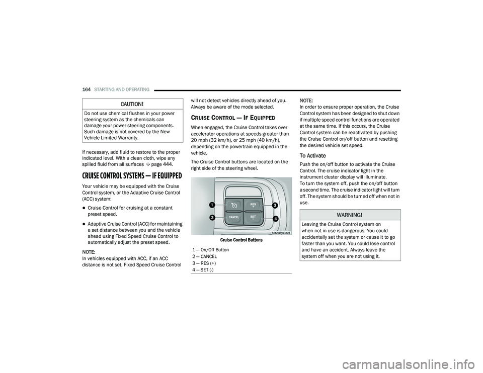
The Cruise Control buttons are located on the
right side of the steering wheel.
Cruise Control Buttons
NOTE:
In order to ensure proper operation, the Cruise
Control system has been designed to shut down
if multiple speed control functions are operated
at the same time. If this occurs, the Cruise
Control system can be reactivated by pushing
the Cruise Control on/off button and resetting
the desired vehicle set speed.
To Activate
Push the on/off button to activate the Cruise
Control. The cruise indicator light in the
instrument cluster display will illuminate.
To turn the system off, push the on/off button
a second time. The cruise indicator light will turn
off. The system should be turned off when not in
use.
CAUTION!
Do not use chemical flushes in your power
steering system as the chemicals can
damage your power steering components.
Such damage is not covered by the New
Vehicle Limited Warranty.
1 — On/Off Button
2 — CANCEL
3 — RES (+)
4 — SET (-)
WARNING!
Leaving the Cruise Control system on
when not in use is dangerous. You could
accidentally set the system or cause it to go
faster than you want. You could lose control
and have an accident. Always leave the
system off when you are not using it.
21_DPF_OM_EN_USC_t.book Page 164
Page 170 of 463
168STARTING AND OPERATING
Adaptive Cruise Control (ACC) Menu
The instrument cluster display will show the
current ACC system settings. The information it
displays depends on ACC system status.
Push the ACC on/off button until one of the
following appears in the instrument cluster
display:
Adaptive Cruise Control Off
When ACC is deactivated, the display will read
“Adaptive Cruise Control Off.”
Adaptive Cruise Control Ready
When ACC is activated, but the vehicle speed
setting has not been selected, the display will
read “Adaptive Cruise Control Ready.”
Adaptive Cruise Control Set
When the RES (+) or the SET(-) button is pushed,
the display will read “ACC SET.”
When ACC is set, the set speed will show in the
instrument cluster display.
The ACC screen may display once again if any of
the following ACC activity occurs:
System Cancel
Driver Override
System Off
ACC Proximity Warning
ACC Unavailable Warning
The instrument cluster display will return to the
last display selected after five seconds of no
ACC display activity.
Activating Adaptive Cruise Control (ACC)
The minimum set speed for the ACC system is
20 mph (32 km/h).
When the system is turned on and in the ready
state, the instrument cluster display will read
“ACC Ready.”
When the system is off, the instrument cluster
display will read “Adaptive Cruise Control (ACC)
Off.”
NOTE:
You cannot engage ACC under the following
conditions:
When in 4WD Low
When brakes are applied
When the parking brake is applied
When the automatic transmission is in PARK,
REVERSE or NEUTRAL
When the vehicle speed is below the
minimum speed range
When the brakes are overheated
When the driver’s door is open at low speeds
When the driver’s seat belt is unbuckled at
low speed
Electronic Stability Control (ESC) Full Off
mode is active
To Activate/Deactivate
Push and release the Adaptive Cruise Control
(ACC) on/off button. The ACC menu in the
instrument cluster displays “ACC Ready.”
To turn the system off, push and release the
Adaptive Cruise Control (ACC) on/off button
again. At this time, the system will turn off
and the instrument cluster display will show
“Adaptive Cruise Control (ACC) Off.”
21_DPF_OM_EN_USC_t.book Page 168
Page 172 of 463
170STARTING AND OPERATING
The gear selector is removed from the DRIVE
position.
The Electronic Stability Control/Traction
Control System (ESC/TCS) activates.
The vehicle parking brake is applied.
Driver seat belt is unbuckled at low speeds.
Driver door is opened at low speeds.
A Trailer Sway Control (TSC) event occurs.
The driver switches ESC to Full Off mode.
The braking temperature exceeds normal
range (overheated).
The trailer brake is applied manually
(if equipped).
The following conditions will only cancel the ACC
system:
Driver seat belt is unbuckled at low speeds
Driver door is opened at low speeds
To Turn Off
The system will turn off and clear the set speed
in memory if:
The Adaptive Cruise Control (ACC) on/off
button is pushed
The Fixed Speed Cruise Control on/off button
is pushed
The ignition is placed in the OFF position
4WD Low is engaged
To Resume
If there is a set speed in memory push the RES
(+) button and then remove your foot from the
accelerator pedal. The instrument cluster
display will display the last set speed.
Resume can be used at any speed above
20 mph (32 km/h) when only Fixed Speed
Cruise Control is being used.
Resume can be used at any speed above 0 mph
(0 km/h) when ACC is active. NOTE:
While in ACC mode when the vehicle comes
to a complete stop longer than two seconds,
the system will cancel. The driver will have
to apply the brakes to keep the vehicle at a
standstill.
ACC cannot be resumed if there is a
stationary vehicle in front of your vehicle in
close proximity.
WARNING!
The Resume function should only be used if
traffic and road conditions permit. Resuming
a set speed that is too high or too low for
prevailing traffic and road conditions could
cause the vehicle to accelerate or decelerate
too sharply for safe operation. Failure to
follow these warnings can result in a collision
and death or serious personal injury.
21_DPF_OM_EN_USC_t.book Page 170
Page 173 of 463
STARTING AND OPERATING171
To Vary The Speed Setting
To Increase Or Decrease The Set Speed
After setting a speed, you can increase the
set speed by pushing the RES (+) button, or
decrease speed by pushing the SET (-) button.
U.S. Speed (mph)
Pushing the RES (+) button, or SET (-) button
once will result in a 1 mph speed adjustment.
Each subsequent tap of the button results in
an adjustment of 1 mph.
If the button is continually pushed, the set
speed will continue to adjust in 5 mph incre -
ments until the button is released. The new
set speed is reflected in the instrument
cluster display.
Metric Speed (km/h)
Pushing the RES (+) button, or SET (-) button
once will result in a 1 km/h speed adjust -
ment. Each subsequent tap of the button
results in an adjustment of 1 km/h.
If the button is continually pushed, the set
speed will continue to adjust in 10 km/h
increments until the button is released.
The new set speed is reflected in the instru -
ment cluster display. When An ACC Distance Is Also Set:
When you use the SET (-) button to decel -
erate, if the engine’s braking power does not
slow the vehicle sufficiently to reach the set
speed, the brake system will automatically
slow the vehicle.
The ACC system applies the brake down to a
full stop when following the vehicle in front.
If your vehicle follows the vehicle in front to
a standstill, your vehicle will release the
brakes two seconds after coming to a
complete stop.
The ACC system maintains set speed when
driving uphill and downhill. However, a slight
speed change on moderate hills is normal.
In addition, downshifting may occur while
climbing uphill or descending downhill. This
is normal operation and necessary to main-
tain set speed. When driving uphill and
down -hill, the ACC system will cancel if the
braking temperature exceeds normal range
(over -heated).
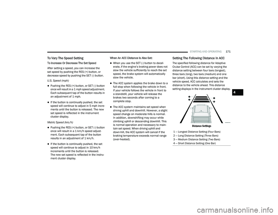
Setting The Following Distance In ACC
The specified following distance for Adaptive
Cruise Control (ACC) can be set by varying the
distance setting between four bars (longest),
three bars (long), two bars (medium) and one
bar (short). Using this distance setting and the
vehicle speed, ACC calculates and sets the
distance to the vehicle ahead. This distance
setting displays in the instrument cluster display.
Distance Settings
1 — Longest Distance Setting (Four Bars)
2 — Long Distance Setting (Three Bars)
3 — Medium Distance Setting (Two Bars)
4 — Short Distance Setting (One Bar)
4
21_DPF_OM_EN_USC_t.book Page 171
Page 188 of 463
186STARTING AND OPERATING
CHANGING LANESENSE STATUS
The LaneSense system has settings to adjust
the intensity (Low/Medium/High) of the torque
warning and the warning zone sensitivity (Early/
Medium/Late) that you can configure through
the Uconnect system Úpage 228.
NOTE:
When enabled the system operates above
37 mph (60 km/h) and below 112 mph (180 km/h).
Use of the turn signal suppresses the warnings.
The system will not apply torque to the
steering wheel whenever a safety system
engages (Anti-Lock Brakes, Traction Control
System, Electronic Stability Control, Forward
Collision Warning, etc.).
PARKVIEW REAR BACK UP CAMERA
The ParkView Rear Back Up Camera allows
you to see an on-screen image of the rear
surroundings of your vehicle whenever the gear
selector is put into REVERSE. The image will be
displayed on the Navigation/Multimedia radio
display screen along with a caution note to
“Check Entire Surroundings” across the top of
the screen. After five seconds this note will
disappear. The ParkView Camera is located in
the center of the tailgate handle.
NOTE:
For the 3500, 4500, and 5500 Chassis Cab
vehicles, the Rear Backup Camera is shipped
loose and not installed. Please refer to the Ram
Body Builders Guide for more information.
Manual Activation Of The Rear View
Camera:
1. Press the "Controls" button located on the bottom of the Uconnect display.
2. Press the "Back Up Camera" icon to turn the Rear View Camera system on.
When the vehicle is shifted out of REVERSE (with
camera delay turned off), the rear camera mode is exited and the previous screen appears. When
the vehicle is shifted out of REVERSE (with
camera delay turned on), the camera image will
continue to be displayed for up to 10 seconds
unless the following conditions occur: The vehicle
speed exceeds 8 mph (13 km/h), the vehicle is
shifted into PARK, the vehicle’s ignition is placed
in the OFF position, or the user presses image
defeat “X” to exit out of the camera video display.
Whenever the Rear View Camera image is
activated through the "Backup Camera" button
in the Controls menu, and the vehicle speed is
greater than, or equal to, 8 mph (13 km/h), a
display timer for the image is initiated. The
image will continue to be displayed until the
display timer exceeds 10 seconds.
NOTE:
If the vehicle speed remains below 8 mph
(13 km/h), the Rear View Camera image will
be displayed continuously until deactivated
via the touchscreen button "X", the transmis -
sion is shifted into PARK, or the ignition is
placed in the OFF position.
The touchscreen button "X" to disable display
of the camera image is made available ONLY
when the vehicle is not in REVERSE.
21_DPF_OM_EN_USC_t.book Page 186
Page 191 of 463
STARTING AND OPERATING189
Zoom View is not available with the AUX
Camera feature.
The display will always default to the Trailer
Camera display (AUX 1).
SURROUND VIEW CAMERA SYSTEM — IF
EQUIPPED
Your vehicle may be equipped with the Surround
View Camera system that allows you to see an
on-screen image of the surroundings and Top
View of your vehicle whenever the gear selector is
put into REVERSE or manually activated via the
Uconnect system. The Top View of the vehicle will
show which doors are open. The image will be
displayed on the touchscreen display along with
a caution note “Check Entire Surroundings”
across the top of the screen. After five seconds,
this note will disappear. The Surround View
Camera system is comprised of three sequential
cameras located in the front grille and side
mirrors, in addition to a fourth Rear Back Up
Camera.
NOTE:
For the 3500, 4500, and 5500 Chassis Cab vehi
-
cles, the Rear Backup Camera is shipped loose
and not installed. Please refer to the Ram Body
Builder’s Guide for more information.
The Surround View Camera system has
programmable settings that may be selected
through the Uconnect system Ú page 228.
Press this button on the touchscreen
to enter the Surround View Camera
menu in the Uconnect system.
When the vehicle is shifted into REVERSE, the
Rear View and Top View is the default view of
the system.
If the camera delay is turned on, the camera
image will display for up to 10 seconds after
shifting out of REVERSE. The camera image will
not display for 10 seconds if the vehicle speed
exceeds 8 mph (13 km/h), the vehicle is shifted
into PARK, or the ignition is placed in the OFF
position. The “X” button on the touchscreen
disables the display of the camera image.
If the camera delay is turned off, the camera
image will close and display the previous screen
after shifting out of REVERSE. If active guidelines are enabled, the lines are
overlaid on the image in the Rear View to
illustrate the width of the vehicle. The view
will also include the side view mirrors and its
projected back up path based on the steering
wheel position.
There are different colored zones to indicate the
distance to the rear of the vehicle. Refer to the
chart below:
Modes Of Operation
Standard Rear View can be manually activated
by selecting “Back Up Camera” through the
Controls menu within the Uconnect system.
Top View
The Top View will show in the Uconnect system
with Rear View and Front View in a split screen
display. There are integrated ParkSense arcs in
the image at the front and rear of the vehicle.
Zone
Distance To The Rear Of The
Vehicle
Red 0 - 1 ft (0 - 30 cm)
Yellow 1 ft - 6.5 ft (30 cm - 2 m)
Green 6.5 ft or greater
(2 m or greater)
4
21_DPF_OM_EN_USC_t.book Page 189
Page 193 of 463
STARTING AND OPERATING191
Cargo Camera
Pressing the Cargo Camera soft key
will provide a full screen view of the
cargo area.
NOTE:
If the Cargo Camera view was selected through
the Surround View screen, exiting out of the
Cargo Camera screen will return to the Surround
View screen. If the Cargo Camera was manually
activated through the Controls menu of the
Uconnect display, exiting out of the display
screen will return to the Controls menu.
Trailer Reverse Guidance
Pressing the Trailer Reverse Guidance
soft key will provide a full screen view of
the cargo area and trailer.
Pressing the Left & Right Tow Mirror
Split Screen View button within the
Trailer Reverse Guidance screen will
display a split screen to allow the
driver to see both sides of the trailer at the
same time. This view allows the driver to pan
left/right to better frame the trailer in the image. NOTE:
Trailer Reverse Guidance can only be selected
through the Surround View screen; exiting out of
the Trailer Reverse Guidance screen will return
to the Surround View screen.
Zoom View
When the Rear View image is being displayed,
and the vehicle speed is below 8 mph (13 km/h)
while in any gear, Zoom View is available.
By pressing the “magnifying glass” icon in the
upper left of the display screen, the image will
zoom in to four times the standard view. Pressing
the icon a second time will return the view to the
standard Rear View.
When Zoom View is selected while the vehicle is
in REVERSE, then shifted to DRIVE, the camera
delay view will display the standard Back Up
Camera view. If the vehicle is then returned to
REVERSE gear from DRIVE, the Zoom View
selection will automatically resume.
Shifting to NEUTRAL from any gear will maintain
the selected view (Zoom or Standard) as long as
the vehicle is below 8 mph (13 km/h).
If the vehicle is in PARK, Zoom View is available
until the gear selector is placed in DRIVE or
REVERSE and speeds are at or above 8 mph
(13 km/h).NOTE:
If the vehicle is in DRIVE, NEUTRAL, or
REVERSE, and speed is greater than or equal
to 8 mph (13 km/h), Zoom View is unavail
-
able and the icon will appear gray.
While in Zoom View, the guidelines will not be
visible.
Deactivation
The system is deactivated in the following
conditions if it was activated automatically:
When the vehicle is shifted out of REVERSE
(with camera delay turned on), the camera
image will continue to be displayed for up
to 10 seconds unless the vehicle speed
exceeds 8 mph (13 km/h), the vehicle is
shifted into PARK or the ignition is placed in
the OFF position. There is a touchscreen
button “X” to disable the display of the
camera image.
When the vehicle is shifted out of REVERSE
(with camera delay turned off), the Surround
View Camera mode is exited and the last
known screen appears again.
4
21_DPF_OM_EN_USC_t.book Page 191
Page 205 of 463
STARTING AND OPERATING203
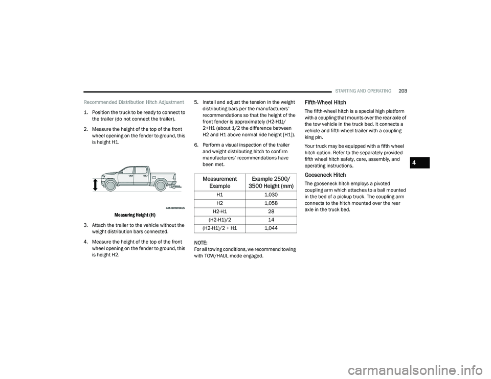
Recommended Distribution Hitch Adjustment
1. Position the truck to be ready to connect to
the trailer (do not connect the trailer).
2. Measure the height of the top of the front wheel opening on the fender to ground, this
is height H1.
Measuring Height (H)
3. Attach the trailer to the vehicle without the weight distribution bars connected.
4. Measure the height of the top of the front wheel opening on the fender to ground, this
is height H2. 5. Install and adjust the tension in the weight
distributing bars per the manufacturers’
recommendations so that the height of the
front fender is approximately (H2-H1)/
2+H1 (about 1/2 the difference between
H2 and H1 above normal ride height [H1]).
6. Perform a visual inspection of the trailer and weight distributing hitch to confirm
manufacturers’ recommendations have
been met.
NOTE:
For all towing conditions, we recommend towing
with TOW/HAUL mode engaged.Fifth-Wheel Hitch
The fifth-wheel hitch is a special high platform
with a coupling that mounts over the rear axle of
the tow vehicle in the truck bed. It connects a
vehicle and fifth-wheel trailer with a coupling
king pin.
Your truck may be equipped with a fifth wheel
hitch option. Refer to the separately provided
fifth wheel hitch safety, care, assembly, and
operating instructions.
Gooseneck Hitch
The gooseneck hitch employs a pivoted
coupling arm which attaches to a ball mounted
in the bed of a pickup truck. The coupling arm
connects to the hitch mounted over the rear
axle in the truck bed.Measurement Example Example 2500/
3500 Height (mm)
H1 1,030
H2 1,058
H2-H1 28
(H2-H1)/2 14
(H2-H1)/2 + H1 1,044
4
21_DPF_OM_EN_USC_t.book Page 203
Page 214 of 463
212STARTING AND OPERATING
Tow/Haul Mode
To reduce potential for automatic transmission
overheating, activate TOW/HAUL mode when
driving in hilly areas, or select a lower gear
range (using the Electronic Range Select (ERS)
shift control) on more severe grades.
Cruise Control — If Equipped
Do not use on hilly terrain or with heavy
loads.
When using the Cruise Control, if you experi -
ence speed drops greater than 10 mph
(16 km/h), disengage until you can get back
to cruising speed.
Use Cruise Control in flat terrain and with
light loads to maximize fuel efficiency.
SNOWPLOW — IF EQUIPPED
Snowplow Prep Packages are available as a
factory installed option. These packages
include components necessary to equip your
vehicle with a snowplow. NOTE:
Before installation of a snowplow it is highly
recommended that the owner/installer obtain
and follow the recommendations contained
within the current Body Builders Guide. See an
authorized dealer, installer or snowplow manu
-
facturer for this information. There are unique
electrical systems that must be connected to
properly ensure operator safety and prevent
overloading vehicle systems.
BEFORE PLOWING
Check the hydraulic system for leaks and
proper fluid level.
Check the mounting bolts and nuts for proper
tightness.
Check the runners and cutting edge for
excessive wear. The cutting edge should be
¼ to ½ inches (6 cm to 1.2 cm) above ground
in snow plowing position.
Check that snowplow lighting is connected
and functioning properly.
SNOWPLOW PREP PACKAGE MODEL
A
VAILABILITY
For Information about snowplow applications
visit www.ramtrucks.com or refer to the current
Body Builders Guide.
1. The maximum number of occupants in the
truck should not exceed two.
2. The total GVWR or the Front GAWR or the Rear GAWR should never be exceeded.
3. Cargo capacity will be reduced by the addition of options or passengers, etc.
WARNING!
Attaching a snowplow to this vehicle could
adversely affect performance of the airbag
system in a collision. Do not expect that the
airbag will perform as described earlier in this
manual.
CAUTION!
The “Lamp Out” indicator could illuminate if
exterior lamps are not properly installed.
21_DPF_OM_EN_USC_t.book Page 212