maintenance RAM CHASSIS CAB 2023 Repair Manual
[x] Cancel search | Manufacturer: RAM, Model Year: 2023, Model line: CHASSIS CAB, Model: RAM CHASSIS CAB 2023Pages: 444, PDF Size: 20.51 MB
Page 385 of 444

SERVICING AND MAINTENANCE383
F80 –10 Amp RedOvrdh Con / Assist / 911
F81 –20 Amp YellowTrlr tow Rt turn / Stop
F82 –10 Amp RedSCCM / Cruise control
F83 –10 Amp RedTLR AST / TLR RVS CTL / TLR KNB
F84 –15 Amp Blue
ASBM / HVAC / ICS / R Heated Seats SW
F85 –10 Amp RedORC (Airbag)
F86 –10 Amp RedORC (Airbag)
F87 –10 Amp RedAir Susp / ITBM / SCCM / TLR TPM
F88 –15 Amp BlueIP Cluster
F89 ––Spare
F90 –20 Amp YellowPower Outlet / Batt
F91 ––Power Outlet / Acc
F92 –10 Amp RedInvertor MOD / USB-IP / WCPM *
F93 ––Spare
F94 –10 Amp RedSBW / TCASE SW / TRL TPM - GTWY
F95 –10 Amp RedRR CAM / PRKTRNX/ CHMSL Cam /
Bld SPT SNR / SVUE CAM *
F96 –10 Amp RedTRL Cam *
F97 –20 Amp YellowFront HTD ST PSGR *
F98 –20 Amp YellowFront HTD ST DRIVER *
Cavity Cartridge Fuse Micro FuseDescription
* If Equipped
8
23_DPF_OM_EN_USC_t.book Page 383
Page 386 of 444

384SERVICING AND MAINTENANCE
BULB REPLACEMENT
Replacement Bulbs, Names, And Part Numbers
In the instance a bulb needs to be replaced, this section includes bulb description and replacement part numbers.
NOTE:See an authorized dealer for LED bulb replacement.F99
–10 Amp RedHVAC / IN-CARTS / CSG / TRL CWY
MOD */ TACH
F100 –10 Amp RedUpfitter Box Feed *
F101 –20 Amp YellowRR HTD ST Right *
F102 –20 Amp YellowRR HTD ST Left / Run RLY #3 *
F103 –10 Amp RedHeadLamp AFLS *
F104 –20 Amp YellowUCI Port / USB Rear
Cavity Cartridge Fuse Micro FuseDescription
* If Equipped
Interior Bulbs
Bulb Name Bulb Number
Overhead Console Lamps TS 212–9
Dome Lamp 7679
NOTE:For lighted switches, see an authorized dealer for replacement instructions.
23_DPF_OM_EN_USC_t.book Page 384
Page 387 of 444

SERVICING AND MAINTENANCE385
Exterior Bulbs
Bulb Name Bulb Number
Low Beam (Halogen Reflector Headlamp) H11LL
High Beam (Halogen Reflector Headlamp) 9005LL
Low & High Beam LED
Low & High Beam LED
Turn Signal / Front Position (Halogen Reflector Headlamp) 7444NA
Turn Signal LED
Front Position LED
Turn Signal (LED Reflector Headlamp) 7444NA
Front Side Marker LED
Front Fog Lamps (Halogen Reflector Headlamp) H11LL
Front Fog Lamps LED
Side Indicators LED
Center High Mounted Stop Lamp (CHMSL) 921
Cab Roof Marker Lamps 194NA
Box Off Tail Lamps – Stop/Turn/Tail/License Plate 1157
Box Off Tail Lamps – Back Up 1156
8
23_DPF_OM_EN_USC_t.book Page 385
Page 388 of 444

386SERVICING AND MAINTENANCE
Replacing Exterior Bulbs
BASE QUAD: LOW BEAM HEADLAMP, HIGH
BEAM HEADLAMP, FRONT PARK AND TURN —
IF EQUIPPED
Low Beam
See the following steps to replace:
1. Open the hood.
2. Disconnect and isolate the negative battery
cable.
3. Reach into the front wheel house ahead of the front wheel, remove the fastener, and lift the
cover over the access hole in the front of the
wheel house splash shield. Access to the rear
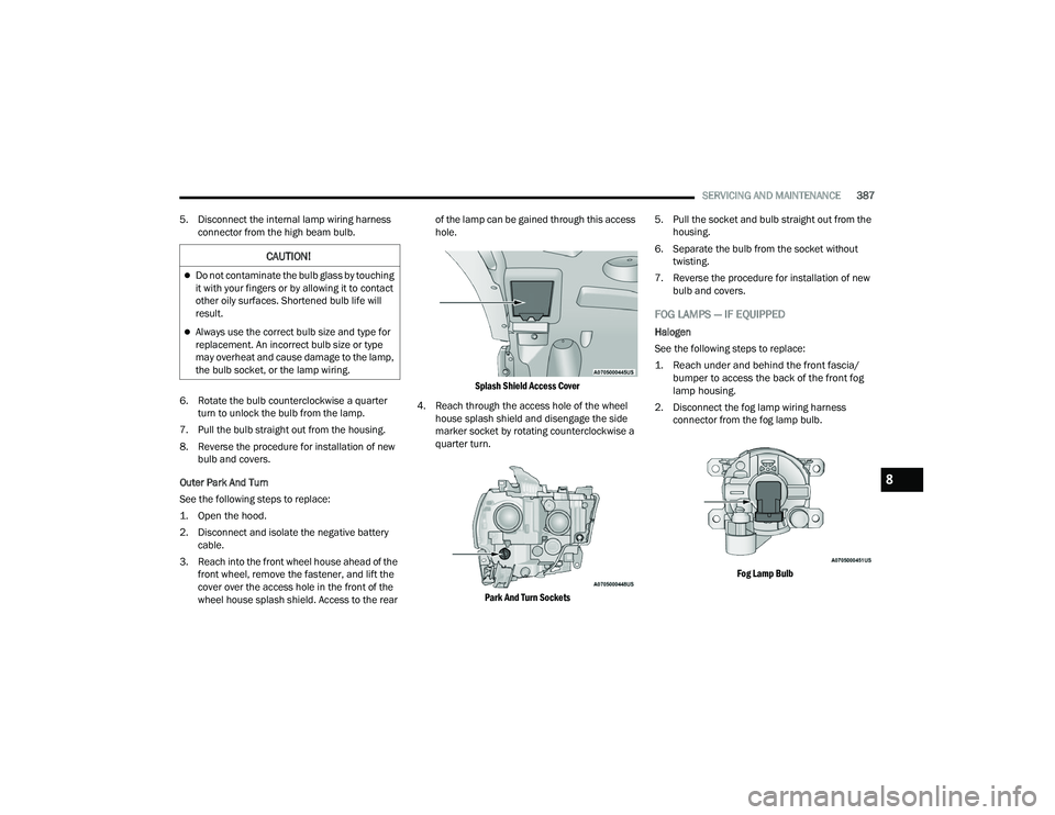
of the lamp can be gained through this access
hole.
Splash Shield Access Cover
4. Reach through the access hole of the wheel
house splash shield and disengage the bulb
access cover by rotating counterclockwise.
Bulb Access Cover
5. Disconnect the internal lamp wiring harness connector from the low beam bulb. 6. Rotate the bulb counterclockwise a quarter
turn to unlock the bulb from the lamp.
7. Pull the bulb straight out from the housing.
8. Reverse the procedure for installation of new bulb and covers.
High Beam
See the following steps to replace:
1. Open the hood.
2. Disconnect and isolate the negative battery cable.
Bulb Access Cover
3. Look under the hood and behind the headlamp to find the high beam bulb access
cover.
4. Reach behind the headlamp and disengage the access cover by rotating counterclockwise.
CAUTION!
Do not contaminate the bulb glass by touching
it with your fingers or by allowing it to contact
other oily surfaces. Shortened bulb life will
result.
Always use the correct bulb size and type for
replacement. An incorrect bulb size or type
may overheat and cause damage to the lamp,
the bulb socket, or the lamp wiring.
23_DPF_OM_EN_USC_t.book Page 386
Page 389 of 444

SERVICING AND MAINTENANCE387
5. Disconnect the internal lamp wiring harness connector from the high beam bulb.
6. Rotate the bulb counterclockwise a quarter turn to unlock the bulb from the lamp.
7. Pull the bulb straight out from the housing.
8. Reverse the procedure for installation of new bulb and covers.
Outer Park And Turn
See the following steps to replace:
1. Open the hood.
2. Disconnect and isolate the negative battery cable.
3. Reach into the front wheel house ahead of the front wheel, remove the fastener, and lift the
cover over the access hole in the front of the
wheel house splash shield. Access to the rear of the lamp can be gained through this access
hole.
Splash Shield Access Cover
4. Reach through the access hole of the wheel house splash shield and disengage the side
marker socket by rotating counterclockwise a
quarter turn.
Park And Turn Sockets
5. Pull the socket and bulb straight out from the
housing.
6. Separate the bulb from the socket without twisting.
7. Reverse the procedure for installation of new bulb and covers.
FOG LAMPS — IF EQUIPPED
Halogen
See the following steps to replace:
1. Reach under and behind the front fascia/bumper to access the back of the front fog
lamp housing.
2. Disconnect the fog lamp wiring harness connector from the fog lamp bulb.
Fog Lamp Bulb
CAUTION!
Do not contaminate the bulb glass by touching
it with your fingers or by allowing it to contact
other oily surfaces. Shortened bulb life will
result.
Always use the correct bulb size and type for
replacement. An incorrect bulb size or type
may overheat and cause damage to the lamp,
the bulb socket, or the lamp wiring.
8
23_DPF_OM_EN_USC_t.book Page 387
Page 390 of 444

388SERVICING AND MAINTENANCE
3. Rotate the bulb counterclockwise a quarter turn to unlock the bulb from the housing.
4. Pull the bulb straight out from the housing.
5. Reverse the procedure to install the bulb and cover.
CENTER HIGH MOUNTED STOP LAMP (CHMSL)
WITH CARGO LAMP
See the following steps to replace:
1. Remove the two screws holding the housing/lens to the body as shown.
CHMSL Mounting Screw Locations
2. Separate the connector holding the housing
and wiring harness to the body.
CHMSL Connector Location
3. Turn the desired bulb socket a quarter turn and remove the socket and bulb from housing.
4. Pull the desired bulb straight from the socket.
Outside Bulbs: Cargo Lamps
Inside Bulb: Center High Mounted Stop
Lamp
5. Reverse the procedure for installation of bulbs and housing.
CAB TOP CLEARANCE LAMPS — IF EQUIPPED
See the following steps to replace:
1. Remove the two screws from the top of the lamp.
Removing Rear Screw From Clearance Lamp
2. Rotate the bulb socket a quarter turn and pull it from the lamp assembly.
CAUTION!
Do not contaminate the bulb glass by touching it
with your fingers or by allowing it to contact other
oily surfaces. Shortened bulb life will result.
CAUTION!
Do not contaminate the bulb glass by touching it
with your fingers or by allowing it to contact other
oily surfaces. Shortened bulb life will result.
23_DPF_OM_EN_USC_t.book Page 388
Page 391 of 444

SERVICING AND MAINTENANCE389
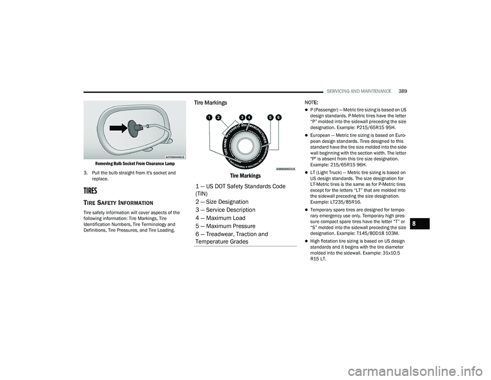
Removing Bulb Socket From Clearance Lamp
3. Pull the bulb straight from it's socket and replace.
TIRES
TIRE SAFETY INFORMATION
Tire safety information will cover aspects of the
following information: Tire Markings, Tire
Identification Numbers, Tire Terminology and
Definitions, Tire Pressures, and Tire Loading.
Tire Markings
Tire Markings
NOTE:
P (Passenger) — Metric tire sizing is based on US
design standards. P-Metric tires have the letter
“P” molded into the sidewall preceding the size
designation. Example: P215/65R15 95H.
European — Metric tire sizing is based on Euro -
pean design standards. Tires designed to this
standard have the tire size molded into the side -
wall beginning with the section width. The letter
"P" is absent from this tire size designation.
Example: 215/65R15 96H.
LT (Light Truck) — Metric tire sizing is based on
US design standards. The size designation for
LT-Metric tires is the same as for P-Metric tires
except for the letters “LT” that are molded into
the sidewall preceding the size designation.
Example: LT235/85R16.
Temporary spare tires are designed for tempo -
rary emergency use only. Temporary high pres -
sure compact spare tires have the letter “T” or
“S” molded into the sidewall preceding the size
designation. Example: T145/80D18 103M.
High flotation tire sizing is based on US design
standards and it begins with the tire diameter
molded into the sidewall. Example: 31x10.5
R15 LT.
1 — US DOT Safety Standards Code
(TIN)
2 — Size Designation
3 — Service Description
4 — Maximum Load
5 — Maximum Pressure
6 — Treadwear, Traction and
Temperature Grades
8
23_DPF_OM_EN_USC_t.book Page 389
Page 392 of 444

390SERVICING AND MAINTENANCE
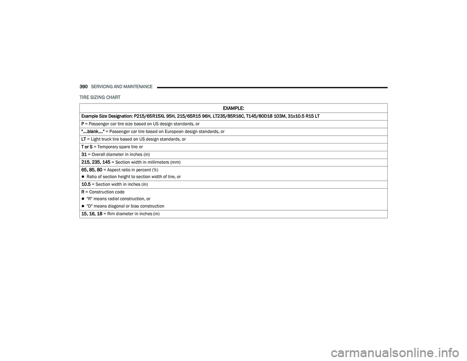
TIRE SIZING CHART
EXAMPLE:
Example Size Designation: P215/65R15XL 95H, 215/65R15 96H, LT235/85R16C, T145/80D18 103M, 31x10.5 R15 LT
P = Passenger car tire size based on US design standards, or
"....blank...." = Passenger car tire based on European design standards, or
LT = Light truck tire based on US design standards, or
T or S = Temporary spare tire or
31 = Overall diameter in inches (in)
215, 235, 145 = Section width in millimeters (mm)
65, 85, 80 = Aspect ratio in percent (%)
Ratio of section height to section width of tire, or
10.5 = Section width in inches (in)
R = Construction code
"R" means radial construction, or
"D" means diagonal or bias construction
15, 16, 18 = Rim diameter in inches (in)
23_DPF_OM_EN_USC_t.book Page 390
Page 393 of 444

SERVICING AND MAINTENANCE391
Service Description:
95 = Load Index
A numerical code associated with the maximum load a tire can carry
H = Speed Symbol
A symbol indicating the range of speeds at which a tire can carry a load corresponding to its load index under certain operating conditions
The maximum speed corresponding to the speed symbol should only be achieved under specified operating conditions (i.e., tire pressure, vehicle loading,
road conditions, and posted speed limits)
Load Identification:
Absence of the following load identification symbols on the sidewall of the tire indicates a Standard Load (SL) tire:
XL = Extra load (or reinforced) tire, or
LL = Light load tire or
C, D, E, F, G = Load range associated with the maximum load a tire can carry at a specified pressure
Maximum Load – Maximum load indicates the maximum load this tire is designed to carry
Maximum Pressure – Maximum pressure indicates the maximum permissible cold tire inflation pressure for this tire
EXAMPLE:
8
23_DPF_OM_EN_USC_t.book Page 391
Page 394 of 444

392SERVICING AND MAINTENANCE
Tire Identification Number (TIN)
The TIN may be found on one or both sides of the tire; however, the date code may only be on one side. Tires with white sidewalls will have the full TIN, including
the date code, located on the white sidewall side of the tire. Look for the TIN on the outboard side of black sidewall tires as mounted on the vehicle. If the TIN is
not found on the outboard side, then you will find it on the inboard side of the tire.
EXAMPLE:
DOT MA L9 ABCD 0301
DOT = Department of Transportation
This symbol certifies that the tire is in compliance with the US Department of Transportation tire safety standards and is approved for highway use
MA = Code representing the tire manufacturing location (two digits)
L9 = Code representing the tire size (two digits)
ABCD = Code used by the tire manufacturer (one to four digits)
03 = Number representing the week in which the tire was manufactured (two digits)
03 means the 3rd week
01 = Number representing the year in which the tire was manufactured (two digits)
01 means the year 2001
Prior to July 2000, tire manufacturers were only required to have one number to represent the year in which the tire was manufactured. Example: 031 could
represent the 3rd week of 1981 or 1991
23_DPF_OM_EN_USC_t.book Page 392