service Ram ProMaster 2020 Owner's Guide
[x] Cancel search | Manufacturer: RAM, Model Year: 2020, Model line: ProMaster, Model: Ram ProMaster 2020Pages: 264, PDF Size: 10.11 MB
Page 75 of 264
SAFETY73
(Continued)
How To Engage The Automatic Locking Mode
1. Buckle the combination lap and shoulder
belt.
2. Grasp the shoulder portion and pull down -
ward until the entire seat belt is extracted.
3. Allow the seat belt to retract. As the seat belt retracts, you will hear a clicking sound.
This indicates the seat belt is now in the
Automatic Locking Mode.
How To Disengage The Automatic Locking Mode
Unbuckle the combination lap/shoulder belt
and allow it to retract completely to disengage
the Automatic Locking Mode and activate the
vehicle sensitive (emergency) locking mode.
Supplemental Restraint Systems (SRS)
Some of the safety features described in this
section may be standard equipment on some
models, or may be optional equipment on
others. If you are not sure, ask an authorized
dealer.
The air bag system must be ready to protect you
in a collision. The Occupant Restraint Controller
(ORC) monitors the internal circuits and inter -
connecting wiring associated with the electrical
Air Bag System Components. Your vehicle may
be equipped with the following Air Bag System
Components:
Air Bag System Components
Occupant Restraint Controller (ORC)
Air Bag Warning Light
Steering Wheel and Column
Instrument Panel
Driver and Front Passenger Air Bags
Seat Belt Buckle Switch
Supplemental Side Air Bags
Front and Side Impact Sensors
Seat Belt Pretensioners
Air Bag Warning Light
The Occupant Restraint Controller
(ORC) monitors the readiness of the
electronic parts of the air bag system
whenever the ignition switch is in the
AVV/START or MAR/ACC/ON/RUN position. If
the ignition switch is in the STOP/OFF/LOCK
position the air bag system is not on and the air
bags will not inflate.WARNING!
The seat belt assembly must be replaced if
the switchable Automatic Locking Retractor
(ALR) feature or any other seat belt function
is not working properly when checked
according to the procedures in the Service
Manual.
Failure to replace the seat belt assembly
could increase the risk of injury in colli -
sions.
Do not use the Automatic Locking Mode to
restrain occupants who are wearing the
seat belt or children who are using booster
seats. The locked mode is only used to
install rear-facing or forward-facing child
restraints that have a harness for
restraining the child.
WARNING!
(Continued)
4
20_VF_OM_EN_US_t.book Page 73
Page 76 of 264
74SAFETY
The ORC contains a backup power supply
system that may deploy the air bag system even
if the battery loses power or it becomes discon -
nected prior to deployment.
The ORC turns on the Air Bag Warning Light in
the instrument panel for approximately four to
eight seconds for a self-check when the ignition
switch is in the MAR/ACC/ON/RUN position.
After the self-check, the Air Bag Warning Light
will turn off. If the ORC detects a malfunction in
any part of the system, it turns on the Air Bag
Warning Light, either momentarily or continu -
ously. A single chime will sound to alert you if
the light comes on again after initial startup.
The ORC also includes diagnostics that will illu-
minate the instrument panel Air Bag Warning
Light if a malfunction is detected that could
affect the air bag system. The diagnostics also
record the nature of the malfunction. While the
air bag system is designed to be maintenance
free, if any of the following occurs, have an
authorized dealer service the air bag system
immediately.The Air Bag Warning Light does not come on
during the four to eight seconds when the
ignition switch is first in the MAR/ACC/ON/
RUN position.
The Air Bag Warning Light remains on after
the four to eight-second interval.
The Air Bag Warning Light comes on intermit -
tently or remains on while driving.
NOTE:
If the speedometer, tachometer, or any engine
related gauges are not working, the Occupant
Restraint Controller (ORC) may also be
disabled. In this condition the air bags may not
be ready to inflate for your protection. Have an
authorized dealer service the air bag system
immediately.
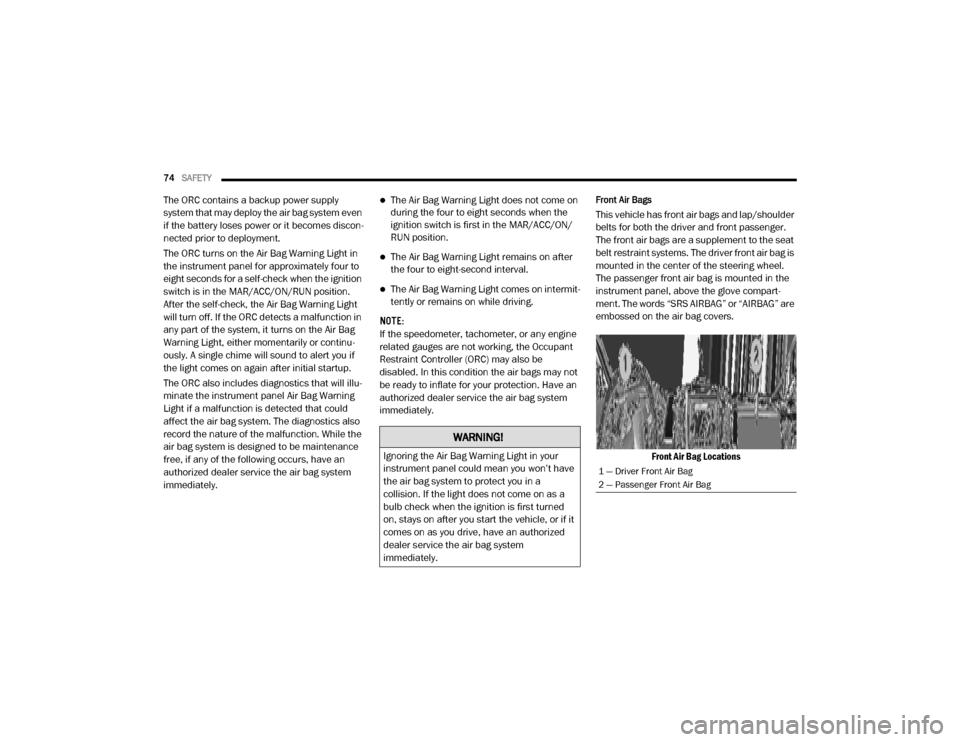
Front Air Bags
This vehicle has front air bags and lap/shoulder
belts for both the driver and front passenger.
The front air bags are a supplement to the seat
belt restraint systems. The driver front air bag is
mounted in the center of the steering wheel.
The passenger front air bag is mounted in the
instrument panel, above the glove compart -
ment. The words “SRS AIRBAG” or “AIRBAG” are
embossed on the air bag covers.
Front Air Bag Locations
WARNING!
Ignoring the Air Bag Warning Light in your
instrument panel could mean you won’t have
the air bag system to protect you in a
collision. If the light does not come on as a
bulb check when the ignition is first turned
on, stays on after you start the vehicle, or if it
comes on as you drive, have an authorized
dealer service the air bag system
immediately.
1 — Driver Front Air Bag
2 — Passenger Front Air Bag
20_VF_OM_EN_US_t.book Page 74
Page 82 of 264
80SAFETY
If A Deployment Occurs
The front air bags are designed to deflate imme -
diately after deployment.
NOTE:
Front and/or side air bags will not deploy in all
collisions. This does not mean something is
wrong with the air bag system.
If you do have a collision which deploys the air
bags, any or all of the following may occur:
The air bag material may sometimes cause
abrasions and/or skin reddening to the occu -
pants as the air bags deploy and unfold. The
abrasions are similar to friction rope burns or
those you might get sliding along a carpet or
gymnasium floor. They are not caused by
contact with chemicals. They are not perma -
nent and normally heal quickly. However, if
you haven’t healed significantly within a few
days, or if you have any blistering, see your
doctor immediately.
As the air bags deflate, you may see some
smoke-like particles. The particles are a
normal by-product of the process that gener -
ates the non-toxic gas used for air bag infla -
tion. These airborne particles may irritate the
skin, eyes, nose, or throat. If you have skin or
eye irritation, rinse the area with cool water.
For nose or throat irritation, move to fresh air.
If the irritation continues, see your doctor. If
these particles settle on your clothing, follow
the garment manufacturer’s instructions for
cleaning.
Do not drive your vehicle after the air bags have
deployed. If you are involved in another collision,
the air bags will not be in place to protect you.
NOTE:
Air bag covers may not be obvious in the inte
-
rior trim, but they will open during air bag
deployment.
After any collision, the vehicle should be
taken to an authorized dealer immediately.
Fuel Cut Off Switch
Your vehicle is equipped with a Fuel Cut Off
switch. In the event of an accident, if the
communication network remains intact, and
the power remains intact, depending on the
nature of the event, the Fuel Cut Off Switch may
perform the following functions:
Cut off fuel to the engine and turn off the
engine.
Flash hazard lights as long as the battery has
power or until the hazard light button is
pressed. The hazard lights can be deacti -
vated by pressing the hazard light button.
Turn on the interior lights, which remain on
as long as the battery has power.
Unlock the power door locks.
WARNING!
Deployed air bags and seat belt
pretensioners cannot protect you in another
collision. Have the air bags, seat belt
pretensioners, and the seat belt retractor
assemblies replaced by an authorized dealer
immediately. Also, have the Occupant
Restraint Controller System serviced as well.
20_VF_OM_EN_US_t.book Page 80
Page 84 of 264

82SAFETY
Event Data Recorder (EDR)
This vehicle is equipped with an Event Data
Recorder (EDR). The main purpose of an EDR is
to record, in certain crash or near crash-like
situations, such as an air bag deployment or
hitting a road obstacle, data that will assist in
understanding how a vehicle’s systems
performed. The EDR is designed to record data
related to vehicle dynamics and safety systems
for a short period of time, typically 30 seconds
or less. The EDR in this vehicle is designed to
record such data as:
How various systems in your vehicle were
operating;
Whether or not the driver and passenger
safety belts were buckled/fastened;
How far (if at all) the driver was depressing
the accelerator and/or brake pedal; and,
How fast the vehicle was traveling.These data can help provide a better under
-
standing of the circumstances in which crashes
and injuries occur.
NOTE:
EDR data are recorded by your vehicle only if a
non-trivial crash situation occurs; no data are
recorded by the EDR under normal driving
conditions and no personal data (e.g., name,
gender, age, and crash location) are recorded.
However, other parties, such as law enforce -
ment, could combine the EDR data with the type
of personally identifying data routinely acquired
during a crash investigation.
To read data recorded by an EDR, special equip -
ment is required, and access to the vehicle or
the EDR is needed. In addition to the vehicle
manufacturer, other parties, such as law
enforcement, that have the special equipment,
can read the information if they have access to
the vehicle or the EDR.
Do not attempt to modify any part of your
air bag system. The air bag may inflate acci -
dentally or may not function properly if
modifications are made. Take your vehicle
to an authorized dealer for any air bag
system service. If your seat, including your
trim cover and cushion, needs to be
serviced in any way (including removal or
loosening/tightening of seat attachment
bolts), take the vehicle to an authorized
dealer. Only manufacturer approved seat
accessories may be used. If it is necessary
to modify the air bag system for persons
with disabilities, contact an authorized
dealer.
WARNING!
(Continued)
20_VF_OM_EN_US_t.book Page 82
Page 92 of 264
90SAFETY
(Continued)
Safety Checks You Should Make Inside The
Vehicle
Seat Belts
Inspect the seat belt system periodically,
checking for cuts, frays, and loose parts.
Damaged parts must be replaced immediately.
Do not disassemble or modify the system.
Front seat belt assemblies must be replaced
after a collision. Rear seat belt assemblies must
be replaced after a collision if they have been
damaged (i.e., bent retractor, torn webbing,
etc.). If there is any question regarding seat belt
or retractor condition, replace the seat belt.
Air Bag Warning Light
The Air Bag warn ing light will turn on for
four to eight secon ds as a bu lb check when
the i gniti on switch is fi rst turned to ON/
RUN. If the l ight is eith er not on du rin g
starting, stays on , or tu rn s on whil e drivin g,
have the system in spected at an authori zed
dealer as soon as possibl e. After the bu lb
ch eck, this light will ill uminate wi th a single
ch ime wh en a fau lt with the Air Bag System
has been d etected. It will stay on un til the fau lt is removed . If the light comes on in ter
-
mitten tly or remains on while dri ving, h ave
an authorized deal er service the vehicle
immedi ately.
Refer to “Occupant Restraint Systems” in
“Safety” for further information.
Defroster
Check operation by selecting the defrost mode
and place the blower control on high speed. You
should be able to feel the air directed against
the windshield. See an authorized dealer for
service if your defroster is inoperable.
Floor Mat Safety Information
Always use floor mats designed to fit your
vehicle. Only use a floor mat that does not inter -
fere with the operation of the accelerator, brake
or clutch pedals. Only use a floor mat that is
securely attached using the floor mat fasteners
so it cannot slip out of position and interfere
with the accelerator, brake or clutch pedals or
impair safe operation of your vehicle in other
ways.
WARNING!
An improperly attached, damaged, folded, or
stacked floor mat, or damaged floor mat
fasteners may cause your floor mat to
interfere with the accelerator, brake, or clutch
pedals and cause a loss of vehicle control. To
prevent SERIOUS INJURY or DEATH:
ALWAYS securely attach your floor mat
using the floor mat fasteners. DO NOT
install your floor mat upside down or turn
your floor mat over. Lightly pull to confirm
mat is secured using the floor mat
fasteners on a regular basis.
ALWAYS REMOVE THE EXISTING FLOOR
MAT FROM THE VEHICLE before
installing any other floor mat. NEVER install
or stack an additional floor mat on top of an
existing floor mat.
20_VF_OM_EN_US_t.book Page 90
Page 97 of 264
STARTING AND OPERATING95
(Continued)
AUTOMATIC TRANSMISSION
Do not leave the key fob in or near the
vehicle, or in a location accessible to chil-
dren, and do not leave a vehicle equipped
with Keyless Enter-N-Go in the ACC or ON/
RUN mode. A child could operate power
windows, other controls, or move the
vehicle.
Be sure the parking brake is fully disen -
gaged before driving; failure to do so can
lead to brake failure and a collision.
Always fully apply the parking brake when
leaving your vehicle or it may roll and cause
damage or injury. Also, be certain to leave
the transmission in PARK. Failure to do so
may cause the vehicle to roll and cause
damage or injury.
CAUTION!
If the Brake System Warning Light remains on
with the parking brake released, a brake
system malfunction is indicated. Have the
brake system serviced by an authorized
dealer immediately.
WARNING!
(Continued)
WARNING!
It is dangerous to shift out of PARK or
NEUTRAL if the engine speed is higher than
idle speed. If your foot is not firmly pressing
the brake pedal, the vehicle could accel -
erate quickly forward or in reverse. You
could lose control of the vehicle and hit
someone or something. Only shift into gear
when the engine is idling normally and your
foot is firmly pressing the brake pedal.
Unintended movement of a vehicle could
injure those in or near the vehicle. As with
all vehicles, you should never exit a vehicle
while the engine is running. Before exiting a
vehicle always come to a complete stop,
then apply the parking brake, shift the
transmission into PARK, turn the engine
OFF, and remove the ignition key. Once the
key is removed, the transmission is locked
in PARK, securing the vehicle against
unwanted movement.
When leaving the vehicle, always remove
the ignition key from the vehicle and lock
the vehicle.
Never leave children alone in a vehicle, or
with access to an unlocked vehicle.
Allowing children to be in a vehicle unat -
tended is dangerous for a number of
reasons. A child or others could be seriously
or fatally injured. Children should be
warned not to touch the parking brake,
brake pedal or the transmission gear
selector.
Do not leave the ignition key in or near the
vehicle (or in a location accessible to chil -
dren). A child could operate power
windows, other controls, or move the
vehicle.
WARNING!
(Continued)
5
20_VF_OM_EN_US_t.book Page 95
Page 98 of 264
96STARTING AND OPERATING
NOTE:
You must press and hold the brake pedal while
shifting out of PARK.
Key Ignition Park Interlock
This vehicle is equipped with a Key Ignition Park
Interlock which requires the transmission to be
in PARK before the ignition can be turned to the
LOCK/OFF (key removal) position. The key can
only be removed from the ignition when the igni -
tion is in the LOCK/OFF position, and once
removed the transmission is locked in PARK. NOTE:
If a malfunction occurs, the system will trap the
key in the ignition to warn you that this safety
feature is inoperable. The engine can be started
and stopped but the key cannot be removed
until you obtain service.
Brake/Transmission Shift Interlock System
This vehicle is equipped with a Brake Transmis
-
sion Shift Interlock System (BTSI) that holds the
transmission gear selector in PARK unless the
brakes are applied. To shift the transmission
out of PARK, the ignition must be turned to the
ON/RUN mode (engine running or not), and the
brake pedal must be pressed.
NOTE:
Swivel seats that are unlocked can also prevent
the transmission gear selector from being
moved out of the PARK position. To shift the
transmission out of the PARK position the first
time after cranking is allowed, ensure swivel
seats are locked in the forward facing position.
Six-Speed Automatic Transmission
The transmission gear position display (located
in the instrument cluster) indicates the trans -
mission gear range. You must press the brake
pedal to move the gear selector out of PARK
(Refer to “Brake/Transmission Shift Interlock
System” in this section). To drive, move the gear
selector from PARK or NEUTRAL to the DRIVE
position.
The electronically-controlled transmission
provides a precise shift schedule. The transmis -
sion electronics are self-calibrating; therefore,
the first few shifts on a new vehicle may be
somewhat abrupt. This is a normal condition,
and precision shifts will develop within a few
hundred miles (kilometers).
Gear SelectorCAUTION!
Shift into or out of PARK or REVERSE only
after the vehicle has come to a complete
stop.
Do not shift between PARK, REVERSE,
NEUTRAL, or DRIVE when the engine is
above idle speed.
Before shifting into any gear, make sure
your foot is firmly pressing the brake pedal.
20_VF_OM_EN_US_t.book Page 96
Page 102 of 264

100STARTING AND OPERATING
Transmission Limp Home Mode
Transmission function is monitored electroni -
cally for abnormal conditions. If a condition is
detected that could result in transmission
damage, Transmission Limp Home Mode is acti -
vated. In this mode, the transmission remains
in third gear regardless of which forward gear is
selected. PARK, REVERSE, and NEUTRAL will
continue to operate. The Malfunction Indicator
Light (MIL) may be illuminated. Transmission
Limp Home Mode allows the vehicle to be
driven to an authorized dealer for service
without damaging the transmission. In the event of a momentary problem, the trans
-
mission can be reset to regain all forward gears
by performing the following steps:
1. Stop the vehicle.
2. Shift the transmission into PARK.
3. Turn the ignition OFF.
4. Wait approximately 10 seconds.
5. Restart the engine.
6. Shift into the desired gear range. If the problem is no longer detected, the trans -
mission will return to normal operation.
NOTE:
Even if the transmission can be reset, we
recommend that you visit your authorized
dealer at your earliest possible convenience.
Your authorized dealer has diagnostic equip -
ment to assess the condition of your transmis -
sion.
If the transmission cannot be reset, authorized
dealer service is required.
Electronic Range Select (ERS) Operation
The Electronic Range Select (ERS) shift control
allows the driver to limit the highest available
gear. For example, if you set the transmission
gear limit to 4 (fourth gear), the transmission
will not shift above fourth gear, but will shift
through the lower gears normally.
You can switch between DRIVE and ERS mode
at any vehicle speed. When the gear selector is
in the DRIVE position, the transmission will
operate automatically, shifting between all
available gears. Moving the gear selector to the
ERS position (beside DRIVE) will activate ERS
mode, display the current gear in the instru -
ment cluster, and set that gear as the top avail -
able gear. Once in ERS mode, moving the gear
selector forward (-) or rearward (+) will change
the top available gear.
To exit ERS mode, simply return the gear
selector to the DRIVE position.
WARNING!
Do not downshift for additional engine
braking on a slippery surface. The drive
wheels could lose their grip and the vehicle
could skid, causing a collision or personal
injury.
20_VF_OM_EN_US_t.book Page 100
Page 105 of 264
STARTING AND OPERATING103
Power Steering Fluid Check
Checking the power steering fluid level at a
defined service interval is not required. The fluid
should be checked at every oil change if a leak
is suspected, abnormal noises are apparent,
and/or the system is not functioning as antici -
pated. Coordinate inspection efforts through an
authorized dealer. If necessary, add fluid to restore to the proper
indicated level. With a clean cloth, wipe any
spilled fluid from all surfaces. Refer to “Fluids
And Lubricants” in “Technical Specifications”
for further information.
SPEED CONTROL — IF EQUIPPED
When engaged, the Speed Control takes over
accelerator operations at speeds greater than
25 mph (40 km/h) up to the maximum speed of
100 mph (160 km/h).
The Speed Control lever is located on the left
side of the steering column.
Speed Control Lever NOTE:
In order to ensure proper operation, the Speed
Control system has been designed to shut down
if multiple Speed Control functions are operated
at the same time. If this occurs, the Speed
Control system can be reactivated by rotating
the Speed Control ON/OFF center ring and
resetting the desired vehicle set speed.
To Activate
Rotate the center ring upward on the Speed
Control lever to turn the system on. The Cruise
Indicator Light in the instrument cluster display
will illuminate. To turn the system off, rotate the
center ring upward a second time. The Cruise
Indicator Light will turn off. The system should
be turned off when not in use.WARNING!
Fluid level should be checked on a level
surface and with the engine off to prevent
injury from moving parts and to ensure
accurate fluid level reading. Do not overfill.
Use only manufacturer's recommended
power steering fluid.
CAUTION!
Do not use chemical flushes in your power
steering system as the chemicals can
damage your power steering components.
Such damage is not covered by the New
Vehicle Limited Warranty.
WARNING!
Leaving the Speed Control system on when
not in use is dangerous. You could
accidentally set the system or cause it to go
faster than you want. You could lose control
and have an accident. Always leave the
system off when you are not using it.
5
20_VF_OM_EN_US_t.book Page 103
Page 114 of 264
112STARTING AND OPERATING
VEHICLE LOADING
As required by National Highway Traffic Safety
Administration regulations, your vehicle has a
certification label affixed to the driver's side
door or B-Pillar.
If seats are removed for carrying cargo, do not
exceed the specified GVWR and GAWR.
Vehicle Certification Label
Your vehicle has a Vehicle Certification Label
affixed to the drivers side B-Pillar or the rear of
the driver’s door.
The label contains the following information:
Name of manufacturer
Month and year of manufacture
Gross Vehicle Weight Rating (GVWR)
Gross Axle Weight Rating (GAWR) front
Gross Axle Weight Rating (GAWR) rear
Vehicle Identification Number (VIN)
Type of vehicle
Month, Day, and Hour of manufacture (MDH)
The bar code allows a computer scanner to read
the VIN.
Gross Vehicle Weight Rating (GVWR)
The Gross Vehicle Weight Rating (GVWR) is the
total allowable weight of your vehicle. This
includes driver, passengers, and cargo. The
total load must be limited so that you do not
exceed the GVWR.
Gross Axle Weight Rating (GAWR)
The Gross Axle Weight Rating (GAWR) is the
maximum capacity of the front and rear axles.
Distribute the load over the front and rear axles
evenly. Make sure that you do not exceed either
front or rear GAWR.
Tire Size
The tire size on the Vehicle Certification Label
represents the actual tire size on your vehicle.
Replacement tires must be equal to the load
capacity of this tire size.
Rim Size
This is the rim size that is appropriate for the tire
size listed.
Inflation Pressure
This is the cold tire inflation pressure for your
vehicle for all loading conditions up to full Gross
Axle Weight Rating (GAWR).
Curb Weight
The curb weight of a vehicle is defined as the
total weight of the vehicle with all fluids,
including vehicle fuel, at full capacity condi -
tions, and with no occupants or cargo loaded
into the vehicle. The front and rear curb weight
values are determined by weighing your vehicle
on a commercial scale before any occupants or
cargo are added.
Overloading
The load carrying components (axle, springs,
tires, wheels, etc.) of your vehicle will provide
satisfactory service as long as you do not
exceed the Gross Vehicle Weight Rating (GVWR)
and the front and rear Gross Axle Weight Rating
(GAWR).
WARNING!
Because the front wheels steer the vehicle, it
is important that you do not exceed the
maximum front or rear GAWR. A dangerous
driving condition can result if either rating is
exceeded. You could lose control of the
vehicle and have a collision.
20_VF_OM_EN_US_t.book Page 112