engine overheat Ram ProMaster 2020 Owner's Manual
[x] Cancel search | Manufacturer: RAM, Model Year: 2020, Model line: ProMaster, Model: Ram ProMaster 2020Pages: 264, PDF Size: 10.11 MB
Page 6 of 264

4
VEHICLE LOADING ................................................112
Vehicle Certification Label ............................... 112
Gross Vehicle Weight Rating (GVWR) .............. 112
Gross Axle Weight Rating (GAWR) .................. 112
Tire Size .............................................................112
Rim Size ............................................................ 112
Inflation Pressure ............................................. 112
Curb Weight ...................................................... 112
Overloading ....................................................... 112
Loading .............................................................113
TRAILER TOWING ..................................................113
Common Towing Definitions ............................113
Trailer Hitch Classification ............................... 114
Trailer Towing Weights
(Maximum Trailer Weight Ratings) ................. 115 Trailer And Tongue Weight ..............................115Towing Requirements ..................................... 116
Towing Tips ...................................................... 118
RECREATIONAL TOWING
(BEHIND MOTORHOME, ETC.) ............................120
Towing This Vehicle Behind Another Vehicle .. 120
Recreational Towing ......................................... 120
DRIVING TIPS.........................................................121
Driving On Slippery Surfaces ..........................121
Driving Through Water ....................................121
IN CASE OF EMERGENCY
HAZARD WARNING FLASHERS ..........................123 BULB REPLACEMENT ........................................... 123
Replacement Bulbs .......................................... 123
Replacing Exterior Bulbs .................................. 125
Replacing Interior Bulbs .................................. 127
FUSES..................................................................... 128
Underhood Fuses ............................................. 128
Interior Fuses.................................................... 131
Right Central Pillar Fuses ................................ 132
JACKING AND TIRE CHANGING .......................... 133
Jack Location .................................................... 133
Spare Tire Removal .......................................... 134
Preparations For Jacking ................................. 135
Jacking Instructions ......................................... 136Wheel Covers .................................................... 139
TIRE SERVICE KIT — IF EQUIPPED ...................... 139
Tire Service Kit Storage ................................... 139
Tire Service Kit Components And Operation .. 140Tire Service Kit Usage Precautions ................. 140
Sealing A Tire With Tire Service Kit ................. 142
JUMP STARTING ................................................... 145
Preparations For Jump Start ........................... 145
Jump Starting Procedure ................................. 146
Battery Location ............................................... 147
IF YOUR ENGINE OVERHEATS ............................ 147
GEAR SELECTOR OVERRIDE .............................. 148FREEING A STUCK VEHICLE ............................... 149
TOWING A DISABLED VEHICLE........................... 149
Automatic Transmission .................................. 150
ENHANCED ACCIDENT RESPONSE SYSTEM
(EARS) ....................................................................151
EVENT DATA RECORDER (EDR) .......................... 151
SERVICING AND MAINTENANCE
SCHEDULED SERVICING .....................................152
Maintenance Plan ............................................ 152
Heavy Duty Use Of The Vehicle ....................... 155
ENGINE COMPARTMENT...................................... 156
3.6L Engine ..................................................... 156
Checking Oil Level — Gas Engine ................... 157
Adding Washer Fluid ........................................ 157Maintenance-Free Battery .............................. 157
Pressure Washing ............................................ 158
DEALER SERVICE ................................................. 158
Engine Oil ......................................................... 158Engine Oil Filter ................................................ 159
Engine Air Cleaner Filter ................................. 159
Air Conditioner Maintenance ......................... 160
Body Lubrication .............................................. 161
Windshield Wiper Blades ................................ 162
Exhaust System ............................................... 162
Cooling System................................................. 163
Brake System .................................................. 166
Automatic Transmission
(3.6L Gasoline Engine Only) ............................ 167
RAISING THE VEHICLE..........................................168
20_VF_OM_EN_US_t.book Page 4
Page 35 of 264

GETTING TO KNOW YOUR VEHICLE33
Climate Control Functions
A/C (Air Conditioning)
The Air Conditioning (A/C) button allows the
operator to manually activate or deactivate the
air conditioning system. When the air condi -
tioning system is turned on, cool dehumidified
air will flow through the outlets into the cabin.
For improved fuel economy, press the A/C
button to turn off the air conditioning and manu -
ally adjust the blower and airflow mode settings.
Also, make sure to select only Panel, Bi-Level or
Floor modes.
NOTE:
For Manual Climate Controls, if the system is
in Mix, Floor or Defrost Mode, the A/C can be
turned off, but the A/C system shall remain
active to prevent fogging of the windows.
If fog or mist appears on the windshield or
side glass, select Defrost mode, and increase
blower speed if needed.
If your air conditioning performance seems
lower than expected, check the front of the
A/C condenser (located in front of the radi -
ator), for an accumulation of dirt or insects.
Clean with a gentle water spray from the front
of the radiator and through the condenser.
Recirculation
In cold weather, use of Recirculation mode may
lead to excessive window fogging. The Recircu -
lation feature may be unavailable if conditions
exist that could create fogging on the inside of
the windshield. On systems with Manual
Climate Controls, the Recirculation mode is not
allowed in Defrost mode to improve window
clearing operation. Recirculation is disabled
automatically if this mode is selected.
Attempting to use Recirculation while in this
mode causes the LED in the control button to
blink and then turns off.
Operating Tips
NOTE:
Refer to the chart at the end of this section for
suggested control settings for various weather
conditions.
Summer Operation
The engine cooling system must be protected
with a high-quality antifreeze coolant to provide
proper corrosion protection and to protect
against engine overheating. A solution of 50%
OAT (Organic Additive Technology) coolant that
meets the requirements of FCA Material Stan -dard MS.90032 and 50% water is recom
-
mended. Refer to “Fluids And Lubricants” in
“Technical Specifications” for proper coolant
selection.
Winter Operation
Use of the air Recirculation mode during Winter
months is not recommended because it may
cause window fogging.
Vacation Storage
Any time you store your vehicle or keep it out of
service (i.e., vacation) for two weeks or more,
run the air conditioning system at idle for about
five minutes in the fresh air and high blower
setting. This will ensure adequate system lubri -
cation to minimize the possibility of compressor
damage when the system is started again.
Window Fogging
Interior fogging on the windshield can be quickly
removed by turning the mode selector to
Defrost. The Defrost/Floor mode can be used to
maintain a clear windshield and provide suffi -
cient heating. If side window fogging becomes a
problem increase blower speed. Vehicle
windows tend to fog on the inside in mild but
rainy or humid weather.
2
20_VF_OM_EN_US_t.book Page 33
Page 44 of 264
42GETTING TO KNOW YOUR INSTRUMENT PANEL
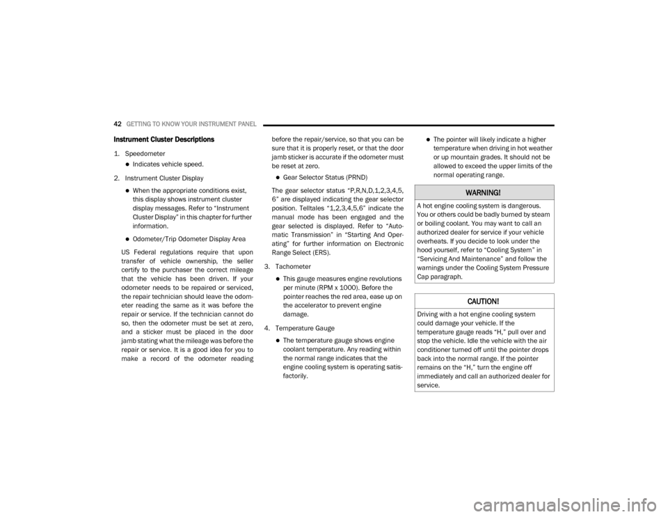
Instrument Cluster Descriptions
1. Speedometer
Indicates vehicle speed.
2. Instrument Cluster Display
When the appropriate conditions exist,
this display shows instrument cluster
display messages. Refer to “Instrument
Cluster Display” in this chapter for further
information.
Odometer/Trip Odometer Display Area
US Federal regulations require that upon
transfer of vehicle ownership, the seller
certify to the purchaser the correct mileage
that the vehicle has been driven. If your
odometer needs to be repaired or serviced,
the repair technician should leave the odom -
eter reading the same as it was before the
repair or service. If the technician cannot do
so, then the odometer must be set at zero,
and a sticker must be placed in the door
jamb stating what the mileage was before the
repair or service. It is a good idea for you to
make a record of the odometer reading before the repair/service, so that you can be
sure that it is properly reset, or that the door
jamb sticker is accurate if the odometer must
be reset at zero.
Gear Selector Status (PRND)
The gear selector status “P,R,N,D,1,2,3,4,5,
6” are displayed indicating the gear selector
position. Telltales “1,2,3,4,5,6” indicate the
manual mode has been engaged and the
gear selected is displayed. Refer to “Auto -
matic Transmission” in “Starting And Oper -
ating” for further information on Electronic
Range Select (ERS).
3. Tachometer
This gauge measures engine revolutions
per minute (RPM x 1000). Before the
pointer reaches the red area, ease up on
the accelerator to prevent engine
damage.
4. Temperature Gauge
The temperature gauge shows engine
coolant temperature. Any reading within
the normal range indicates that the
engine cooling system is operating satis-
factorily.
The pointer will likely indicate a higher
temperature when driving in hot weather
or up mountain grades. It should not be
allowed to exceed the upper limits of the
normal operating range.
WARNING!
A hot engine cooling system is dangerous.
You or others could be badly burned by steam
or boiling coolant. You may want to call an
authorized dealer for service if your vehicle
overheats. If you decide to look under the
hood yourself, refer to “Cooling System” in
“Servicing And Maintenance” and follow the
warnings under the Cooling System Pressure
Cap paragraph.
CAUTION!
Driving with a hot engine cooling system
could damage your vehicle. If the
temperature gauge reads “H,” pull over and
stop the vehicle. Idle the vehicle with the air
conditioner turned off until the pointer drops
back into the normal range. If the pointer
remains on the “H,” turn the engine off
immediately and call an authorized dealer for
service.
20_VF_OM_EN_US_t.book Page 42
Page 50 of 264
48GETTING TO KNOW YOUR INSTRUMENT PANEL
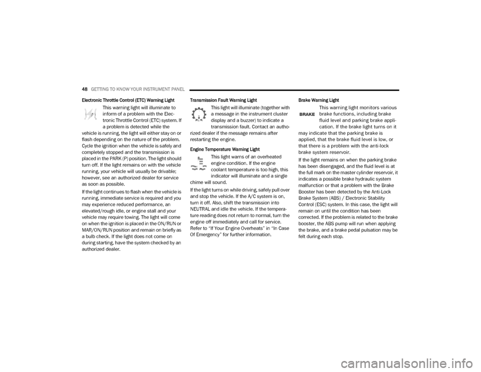
Electronic Throttle Control (ETC) Warning Light
This warning light will illuminate to
inform of a problem with the Elec -
tronic Throttle Control (ETC) system. If
a problem is detected while the
vehicle is running, the light will either stay on or
flash depending on the nature of the problem.
Cycle the ignition when the vehicle is safely and
completely stopped and the transmission is
placed in the PARK (P) position. The light should
turn off. If the light remains on with the vehicle
running, your vehicle will usually be drivable;
however, see an authorized dealer for service
as soon as possible.
If the light continues to flash when the vehicle is
running, immediate service is required and you
may experience reduced performance, an
elevated/rough idle, or engine stall and your
vehicle may require towing. The light will come
on when the ignition is placed in the ON/RUN or
MAR/ON/RUN position and remain on briefly as
a bulb check. If the light does not come on
during starting, have the system checked by an
authorized dealer.
Transmission Fault Warning Light
This light will illuminate (together with
a message in the instrument cluster
display and a buzzer) to indicate a
transmission fault. Contact an autho -
rized dealer if the message remains after
restarting the engine.
Engine Temperature Warning Light
This light warns of an overheated
engine condition. If the engine
coolant temperature is too high, this
indicator will illuminate and a single
chime will sound.
If the light turns on while driving, safely pull over
and stop the vehicle. If the A/C system is on,
turn it off. Also, shift the transmission into
NEUTRAL and idle the vehicle. If the tempera -
ture reading does not return to normal, turn the
engine off immediately and call for service.
Refer to “If Your Engine Overheats” in “In Case
Of Emergency” for further information.
Brake Warning Light
This warning light monitors various
brake functions, including brake
fluid level and parking brake appli -
cation. If the brake light turns on it
may indicate that the parking brake is
applied, that the brake fluid level is low, or
that there is a problem with the anti-lock
brake system reservoir.
If the light remains on when the parking brake
has been disengaged, and the fluid level is at
the full mark on the master cylinder reservoir, it
indicates a possible brake hydraulic system
malfunction or that a problem with the Brake
Booster has been detected by the Anti-Lock
Brake System (ABS) / Electronic Stability
Control (ESC) system. In this case, the light will
remain on until the condition has been
corrected. If the problem is related to the brake
booster, the ABS pump will run when applying
the brake, and a brake pedal pulsation may be
felt during each stop.
20_VF_OM_EN_US_t.book Page 48
Page 52 of 264
50GETTING TO KNOW YOUR INSTRUMENT PANEL
Yellow Warning Lights
Immobilizer Fail / VPS Electrical Alarm Indicator
Light
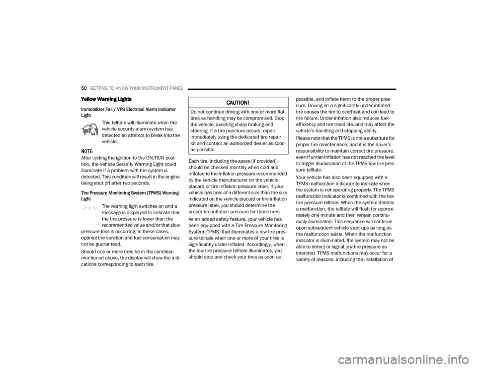
This telltale will illuminate when the
vehicle security alarm system has
detected an attempt to break into the
vehicle.
NOTE:
After cycling the ignition to the ON/RUN posi -
tion, the Vehicle Security Warning Light could
illuminate if a problem with the system is
detected. This condition will result in the engine
being shut off after two seconds.
Tire Pressure Monitoring System (TPMS) Warning
Light
The warning light switches on and a
message is displayed to indicate that
the tire pressure is lower than the
recommended value and/or that slow
pressure loss is occurring. In these cases,
optimal tire duration and fuel consumption may
not be guaranteed.
Should one or more tires be in the condition
mentioned above, the display will show the indi -
cations corresponding to each tire. Each tire, including the spare (if provided),
should be checked monthly when cold and
inflated to the inflation pressure recommended
by the vehicle manufacturer on the vehicle
placard or tire inflation pressure label. If your
vehicle has tires of a different size than the size
indicated on the vehicle placard or tire inflation
pressure label, you should determine the
proper tire inflation pressure for those tires.
As an added safety feature, your vehicle has
been equipped with a Tire Pressure Monitoring
System (TPMS) that illuminates a low tire pres
-
sure telltale when one or more of your tires is
significantly under-inflated. Accordingly, when
the low tire pressure telltale illuminates, you
should stop and check your tires as soon as possible, and inflate them to the proper pres
-
sure. Driving on a significantly under-inflated
tire causes the tire to overheat and can lead to
tire failure. Under-inflation also reduces fuel
efficiency and tire tread life, and may affect the
vehicle’s handling and stopping ability.
Please note that the TPMS is not a substitute for
proper tire maintenance, and it is the driver’s
responsibility to maintain correct tire pressure,
even if under-inflation has not reached the level
to trigger illumination of the TPMS low tire pres -
sure telltale.
Your vehicle has also been equipped with a
TPMS malfunction indicator to indicate when
the system is not operating properly. The TPMS
malfunction indicator is combined with the low
tire pressure telltale. When the system detects
a malfunction, the telltale will flash for approxi -
mately one minute and then remain continu -
ously illuminated. This sequence will continue
upon subsequent vehicle start-ups as long as
the malfunction exists. When the malfunction
indicator is illuminated, the system may not be
able to detect or signal low tire pressure as
intended. TPMS malfunctions may occur for a
variety of reasons, including the installation of
CAUTION!
Do not continue driving with one or more flat
tires as handling may be compromised. Stop
the vehicle, avoiding sharp braking and
steering. If a tire puncture occurs, repair
immediately using the dedicated tire repair
kit and contact an authorized dealer as soon
as possible.
20_VF_OM_EN_US_t.book Page 50
Page 103 of 264
STARTING AND OPERATING101
NOTE:
To select the proper gear position for maximum
deceleration (engine braking), move the gear
selector into the ERS position, then tap it
forward (-) repeatedly as the vehicle slows. The
transmission will shift to the range from which
the vehicle can best be slowed down.Overdrive Operation
The automatic transmission includes an elec -
tronically controlled Overdrive (sixth gear). The
transmission will automatically shift into Over -
drive if the following conditions are present:
The gear selector is in the DRIVE position.
The transmission fluid has reached an
adequate temperature.
The engine coolant has reached an adequate
temperature.
The vehicle speed is sufficiently high.
The driver is not heavily pressing the
accelerator.
When To Use TOW/HAUL Mode
When driving in hilly areas, towing a trailer,
carrying a heavy load, etc., and frequent trans -
mission shifting occurs, push the TOW/HAUL
switch to activate TOW/HAUL mode. This will
improve performance and reduce the potential
for transmission overheating or failure due to
excessive shifting. When operating in TOW/
HAUL mode, transmission upshifts are delayed,
and the transmission will automatically down -
shift (for engine braking) during steady braking
maneuvers.
The “TOW/HAUL Indicator Light” will illuminate
in the instrument cluster to indicate that TOW/
HAUL mode has been activated. Pushing the
switch a second time restores normal opera -
tion. Normal operation is always the default at
engine start-up. If TOW/HAUL mode is desired,
the switch must be pushed each time the
engine is started.
Instrument
Cluster Display 1
23456D
Actual Gear(s)
Allowed 1
1–21–31–41–51–61–6
5
20_VF_OM_EN_US_t.book Page 101
Page 121 of 264
STARTING AND OPERATING119
Automatic Transmission
The DRIVE range can be selected when towing.
The transmission controls include a drive
strategy to avoid frequent shifting when towing.
However, if frequent shifting does occur while in
DRIVE, select TOW/HAUL mode or select a lower
gear range (using the Electronic Range Select
(ERS) shift control).
NOTE:
Using TOW/HAUL mode or selecting a lower
gear range (using the ERS shift control) while
operating the vehicle under heavy loading
conditions will improve performance and
extend transmission life by reducing excessive
shifting and heat build up. This action will also
provide better engine braking.
When towing a loaded trailer up steep grades at
low speeds, holding your vehicle in first gear
(using the ERS shift control) can help to avoid
transmission overheating.
Tow/Haul Mode
To reduce potential for automatic transmission
overheating, activate TOW/HAUL mode when
driving in hilly areas, or select a lower gear
range (using the Electronic Range Select (ERS)
shift control) on more severe grades.
Speed Control — If Equipped
Do not use on hilly terrain or with heavy
loads.
When using the speed control, if you experi -
ence speed drops greater than 10 mph
(16 km/h), disengage until you can get back
to cruising speed.
Use speed control in flat terrain and with light
loads to maximize fuel efficiency.
Cooling System
To reduce potential for engine and transmission
overheating, take the following actions:
City Driving
In city traffic — while stopped, place the trans -
mission in NEUTRAL, but do not increase engine
idle speed.
Highway Driving
Reduce speed.
Temporarily turn off air conditioning.
5
20_VF_OM_EN_US_t.book Page 119
Page 149 of 264
IN CASE OF EMERGENCY147
3. Disconnect the positive end (+) of the
jumper cable from the positive (+) post of
the booster battery.
4. Disconnect the opposite end of the positive (+) jumper cable from the remote positive
(+) post of the discharged vehicle.
5. Close the cover of the Front Power Distribu -
tion Center.
If frequent jump starting is required to start your
vehicle you should have the battery and
charging system inspected at an authorized
dealer.Battery Location
There are two remote jump starting posts under
the hood which is the recommended jump start
location. If access to the battery is needed, an
access panel on the driver’s side floor will allow
for battery access.
Access Panel
Battery Location
IF YOUR ENGINE OVERHEATS
In any of the following situations, you can
reduce the potential for overheating by taking
the appropriate action.
On the highways — slow down.
In city traffic — while stopped, place the trans -
mission in NEUTRAL (N), but do not increase
the engine idle speed while preventing
vehicle motion with the brakes.
NOTE:
There are steps that you can take to slow down
an impending overheat condition:
If your Air Conditioner (A/C) is on, turn it off.
The A/C system adds heat to the engine
cooling system and turning the A/C off can
help remove this heat.
You can also turn the temperature control to
maximum heat, the mode control to floor and
the blower control to high. This allows the
heater core to act as a supplement to the
radiator and aids in removing heat from the
engine cooling system.
CAUTION!
Accessories plugged into the vehicle power
outlets draw power from the vehicle’s battery,
even when not in use (i.e., cellular devices,
etc.). Eventually, if plugged in long enough
without engine operation, the vehicle’s
battery will discharge sufficiently to degrade
battery life and/or prevent the engine from
starting.
6
20_VF_OM_EN_US_t.book Page 147
Page 151 of 264
IN CASE OF EMERGENCY149
FREEING A STUCK VEHICLE
If your vehicle becomes stuck in mud, sand, or
snow, it can often be moved using a rocking
motion. Turn the steering wheel right and left to
clear the area around the front wheels. Shift
back and forth between DRIVE (D) and
REVERSE (R), while gently pressing the acceler -
ator. Use the least amount of accelerator pedal
pressure that will maintain the rocking motion,
without spinning the wheels or racing the
engine. NOTE:
Push the “ESC OFF” switch, to place the Elec
-
tronic Stability Control (ESC) system in “Partial
OFF” mode, before rocking the vehicle. Refer to
“Electronic Brake Control System” in “Safety”
for further information. Once the vehicle has
been freed, push the “ESC OFF” switch again to
restore “ESC ON” mode.
TOWING A DISABLED VEHICLE
This section describes procedures for towing a
disabled vehicle using a commercial towing
service.
CAUTION!
Racing the engine or spinning the wheels may
lead to transmission overheating and failure.
Allow the engine to idle with the transmission
in NEUTRAL for at least one minute after
every five rocking-motion cycles. This will
minimize overheating and reduce the risk of
transmission failure during prolonged efforts
to free a stuck vehicle.
WARNING!
Fast spinning tires can be dangerous. Forces
generated by excessive wheel speeds may
cause damage, or even failure, of the axle
and tires. A tire could explode and injure
someone. Do not spin your vehicle's wheels
faster than 30 mph (48 km/h) or for longer than 30 seconds continuously without
stopping when you are stuck and do not let
anyone near a spinning wheel, no matter
what the speed.
CAUTION!
When “rocking” a stuck vehicle by shifting
between DRIVE and REVERSE, do not spin
the wheels faster than 15 mph (24 km/h), or drivetrain damage may result.
Spinning the wheels too fast may lead to
transmission overheating and failure. It can
also damage the tires. Do not spin the
wheels above 30 mph (48 km/h) while in
gear (no transmission shifting occurring).
6
20_VF_OM_EN_US_t.book Page 149
Page 164 of 264
162SERVICING AND MAINTENANCE
(Continued)
Windshield Wiper Blades
Clean the rubber edges of the wiper blades and
the windshield periodically with a sponge or soft
cloth and a mild nonabrasive cleaner. This will
remove accumulations of salt or road film.
Operation of the wipers on dry glass for long
periods may cause deterioration of the wiper
blades. Always use washer fluid when using the
wipers to remove salt or dirt from a dry wind -
shield.
Avoid using the wiper blades to remove frost or
ice from the windshield. Keep the blade rubber
out of contact with petroleum products such as
engine oil, gasoline, etc.
NOTE:
Life expectancy of wiper blades varies
depending on geographical area and frequency
of use. Poor performance of blades may be
present with chattering, marks, water lines or
wet spots. If any of these conditions are
present, clean the wiper blades or replace as
necessary.
Exhaust System
The best protection against carbon monoxide
entry into the vehicle body is a properly main -
tained engine exhaust system.
If you notice a change in the sound of the
exhaust system; or if the exhaust fumes can be
detected inside the vehicle; or when the under -
side or rear of the vehicle is damaged; have an
authorized technician inspect the complete
exhaust system and adjacent body areas for
broken, damaged, deteriorated, or misposi -
tioned parts. Open seams or loose connections
could permit exhaust fumes to seep into the
passenger compartment. In addition, have the
exhaust system inspected each time the vehicle
is raised for lubrication or oil change. Replace
as required.
WARNING!
Exhaust gases can injure or kill. They
contain carbon monoxide (CO), which is
colorless and odorless. Breathing it can
make you unconscious and can eventually
poison you. To avoid breathing CO, refer to
“Safety Tips” in “Safety” for further informa -
tion.
A hot exhaust system can start a fire if you
park over materials that can burn. Such
materials might be grass or leaves coming
into contact with your exhaust system. Do
not park or operate your vehicle in areas
where your exhaust system can contact
anything that can burn.
CAUTION!
The catalytic converter requires the use of
unleaded fuel only. Leaded gasoline will
destroy the effectiveness of the catalyst as
an emissions control device and may seri -
ously reduce engine performance and
cause serious damage to the engine.
Damage to the catalytic converter can
result if your vehicle is not kept in proper
operating condition. In the event of engine
malfunction, particularly involving engine
misfire or other apparent loss of perfor -
mance, have your vehicle serviced
promptly. Continued operation of your
vehicle with a severe malfunction could
cause the converter to overheat, resulting
in possible damage to the converter and
vehicle.
WARNING!
(Continued)
20_VF_OM_EN_US_t.book Page 162