RENAULT ALASKAN 2017 Owners Manual
Manufacturer: RENAULT, Model Year: 2017, Model line: ALASKAN, Model: RENAULT ALASKAN 2017Pages: 340, PDF Size: 6.93 MB
Page 211 of 340
•
Avoid sudden steering.
• Avoid following too close to the vehicle in front.
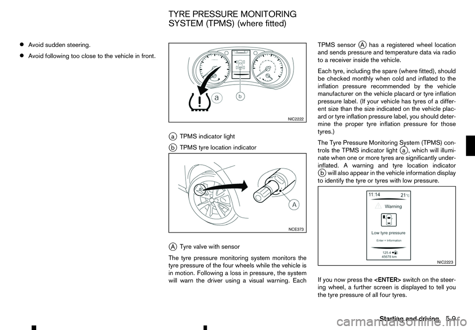
ja TPMS indicator light
j b TPMS tyre location indicator
j A Tyre valve with sensor
The tyre pressure monitoring system monitors the
tyre pressure of the four wheels while the vehicle is
in motion. Following aloss in pressure, the system
will warn the driver using avisual warning. Each TPMS sensor
jAh asaregistered wheel location
and sends pressure and temperature data via radio
to ar eceiver inside the vehicle.
Each tyre, including the spare (where fitted), should
be checked monthly when cold and inflated to the
inflation pressure recommended by the vehicle
manufacturer on the vehicle placard or tyre inflation
pressure label. (If your vehicle has tyres of adiffer-
ent size than the size indicated on the vehicle plac-
ard or tyre inflation pressure label, you should deter-
mine the proper tyre inflation pressure for those
tyres.)
The Tyre Pressure Monitoring System (TPMS) con-
trols the TPMS indicator light j
a, which will illumi-
nate when one or more tyres are significantly under-
inflated. Awarning and tyre location indicator
j bw ill also appear in the vehicle information display
to identify the tyre or tyres with low pressure.
If you now press the
ing wheel, afurther screen is displayed to tell you
the tyre pressure of all four tyres. NIC2222
NCE373
NIC2223
TYRE PRESSURE MONITORING
SYSTEM (TPMS) (where fitted)
Starting and driving5-9
Page 212 of 340
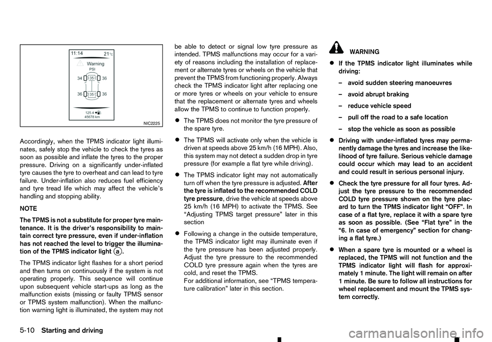
Accordingly, when the TPMS indicator light illumi-
nates, safely stop the vehicle to check the tyres as
soon as possible and inflate the tyres to the proper
pressure. Driving on asignificantly under-inflated
tyre causes the tyre to overheat and can lead to tyre
failure. Under-inflation also reduces fuel efficiency
and tyre tread life which may affect the vehicle’s
handling and stopping ability.
NOTE
The TPMS is not asubstitute for proper tyre main-
tenance. It is the driver’s responsibility to main-
tain correct tyre pressure, even if under-inflation
has not reached the level to trigger the illumina-
tion of the TPMS indicator light j
a.
The TPMS indicator light flashes for ashort period
and then turns on continuously if the system is not
operating properly. This sequence will continue
upon subsequent vehicle start-ups as long as the
malfunction exists (missing or faulty TPMS sensor
or TPMS system malfunction). When the malfunc-
tion warning light is illuminated, the system may not be able to detect or signal low tyre pressure as
intended. TPMS malfunctions may occur for avari-
ety of reasons including the installation of replace-
ment or alternate tyres or wheels on the vehicle that
prevent the TPMS from functioning properly. Always
check the TPMS indicator light after replacing one
or more tyres or wheels on your vehicle to ensure
that the replacement or alternate tyres and wheels
allow the TPMS to continue to function properly.
• The TPMS does not monitor the tyre pressure of
the spare tyre.
• The TPMS will activate only when the vehicle is
driven at speeds above 25 km/h (16 MPH). Also,
this system may not detect
asudden drop in tyre
pressure (for example aflat tyre while driving).
• The TPMS indicator light may not automatically
turn off when the tyre pressure is adjusted.
After
the tyre is inflated to the recommended COLD
tyre pressure,d rive the vehicle at speeds above
25 km/h (16 MPH) to activate the TPMS. See
“Adjusting TPMS target pressure” later in this
section
• Following
achange in the outside temperature,
the TPMS indicator light may illuminate even if
the tyre pressure has been adjusted properly.
Adjust the tyre pressure to the recommended
COLD tyre pressure again when the tyres are
cold, and reset the TPMS.
For additional information, see “TPMS tempera-
ture calibration” later in this section. WARNING
• If the TPMS indicator light illuminates while
driving:
–a void sudden steering manoeuvres
–a void abrupt braking
–r educe vehicle speed
–p ull off the road to asafe location
–s top the vehicle as soon as possible
• Driving with under-inflated tyres may perma-
nently damage the tyres and increase the like-
lihood of tyre failure. Serious vehicle damage
could occur which may lead to an accident
and could result in serious personal injury.
• Check the tyre pressure for all four tyres. Ad-
just the tyre pressure to the recommended
COLD tyre pressure shown on the tyre plac-
ard to turn the TPMS indicator light “OFF”. In
case of
aflat tyre, replace it with aspare tyre
as soon as possible. (See “Flat tyre” in the
“6. In case of emergency” section for chang-
ing aflat tyre.)
• When
aspare tyre is mounted or awheel is
replaced, the TPMS will not function and the
TPMS indicator light will flash for approxi-
mately 1minute. The light will remain on after
1m inute. Be sure to follow all instructions for
wheel replacement and mount the TPMS sys-
tem correctly. NIC2225
5-10 Starting and driving
Page 213 of 340
•
Replacing tyres with those not originally speci-
fied by RENAULT could affect the proper op-
eration of the TPMS.
• RENAULT recommends using only the Emer-
gency Tyre Sealant provided with your vehicle.
Other tyre sealants may damage the valve
stem seal which can cause the tyre to lose air
pressure. Visit an approved dealer or quali-
fied workshop as soon as possible after using
tyre repair sealant (for models equipped with
the emergency tyre puncture repair kit).
CAUTION
• The TPMS may not function properly when the
wheels are equipped with tyre chains or the
wheels are buried in snow.
• Do not place metallised film or any metal parts
(antenna, etc.) on the windows. This may
cause poor reception of the signals from the
tyre pressure sensors, and the TPMS will not
function properly.
Some devices and transmitters may tempo-
rarily interfere with the operation of the TPMS
and cause the TPMS indicator light to illumi-
nate. Some examples are:
–F acilities or electric devices using similar
radio frequencies are near the vehicle.
–I fatransmitter set to similar frequencies is
being used in or near the vehicle. –I
fac omputer (or similar equipment) or a
DC/AC converter is being used in or near
the vehicle.
–I fdevices which transmit electrical noise
are connected to the vehicle’s 12V power
supply.
• When inflating the tyres and checking the tyre
pressure, never bend the valves.
• Special aluminium valves are fitted to mount
the TPMS sensors on the wheels. The TPMS
sensor is fixed at the wheels by
anut. The nut
needs to be correctly fitted at atorque setting
of 7.5 ±0.5 N•m. If the TPMS sensor is tight-
ened exceeding the limit, there is apossibility
the sensor grommet will be damaged. If the
sensor is tightened under the limit, there is a
possibility of causing an air leak.
• Use valve caps that comply with the factory-
fitted valve cap specifications.
• Do not use metal valve caps.
• Fit the valve caps properly. Without the valve
caps the valve and tyre pressure monitor sen-
sors could be damaged.
• Do not damage the valves and sensors when
storing the wheels or fitting different tyres.
• Replace the sensor grommet and washer dur-
ing
atyre change. Once they have been re-
moved, the sensor grommet and washer can-
not be reused and must be replaced. The
TPMS sensors can be used again. •
Use caution when using tyre inflation equip-
ment with
arigid air supply tube, as leverage
applied by the long nozzle can damage the
valve stem.
Starting and driving 5-11
Page 214 of 340
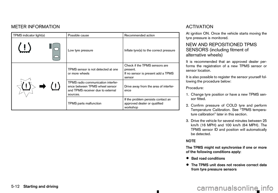
METER INFORMATION
ACTIVATION
At ignition ON. Once the vehicle starts moving the
tyre pressure is monitored.
NEW AND REPOSITIONED TPMSSENSORS (including fitment of
alternative wheels)
It is recommended that an approved dealer per-
forms the registration of anew TPMS sensor or
sensor location.
It is also possible to register the sensor yourself fol-
lowing the procedure below:
Procedure:
1. Change tyre position or have anew TPMS sen-
sor fitted.
2. Confirm pressure of COLD tyre and perform Temperature Calibration. See “TPMS tempera-
ture calibration” later in this section.
3. Drive the vehicle for several minutes between 25 km/h (16 MPH) and 100 km/h (64 MPH). The
TPMS sensor ID and position will automatically
be detected.
NOTE
The TPMS might not synchronise if one or more
of the following conditions apply:
• Bad road conditions
• The TPMS unit does not receive correct data
from tyre pressure sensors TPMS indicator light(s)
Possible cause Recommended action
m Low
tyre pressure
Inflate tyre(s) to the correct pressure
m TPMS
sensor is not detected at one
or more wheels Check if the TPMS sensors are
present.
If no sensor is present add aTPMS
sensor
TPMS radio communication interfer-
ence between TPMS wheel sensor
and TPMS receiver due to external
sources. Drive away from the area of interfer-
ence
TPMS parts malfunction If the problem persists contact an
approved dealer or qualified
workshop
5-12 Starting and driving
Page 215 of 340
•
Driving below 25 km/h (16 MPH)
• Driving above 100 km/h (64 MPH)
• High acceleration
• High deceleration
• In stop and go traffic or traffic waves
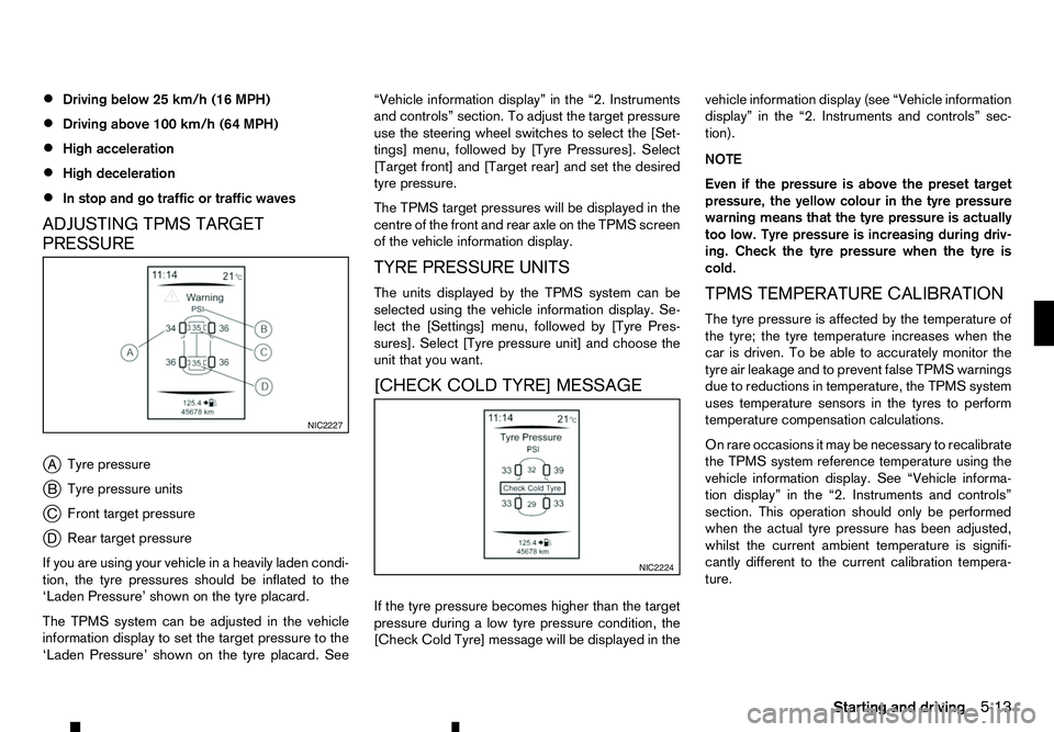
ADJUSTING TPMS TARGET
PRESSURE
j A Tyre pressure
j B Tyre pressure units
j C Front target pressure
j D Rear target pressure
If you are using your vehicle in aheavily laden condi-
tion, the tyre pressures should be inflated to the
‘Laden Pressure’ shown on the tyre placard.
The TPMS system can be adjusted in the vehicle
information display to set the target pressure to the
‘Laden Pressure’ shown on the tyre placard. See “Vehicle information display” in the “2. Instruments
and controls” section. To adjust the target pressure
use the steering wheel switches to select the [Set-
tings] menu, followed by [Tyre Pressures]. Select
[Target front] and [Target rear] and set the desired
tyre pressure.
The TPMS target pressures will be displayed in the centre of the front and rear axle on the TPMS screen
of the vehicle information display.
TYRE PRESSURE UNITS
The units displayed by the TPMS system can be
selected using the vehicle information display. Se-
lect the [Settings] menu, followed by [Tyre Pres-
sures]. Select [Tyre pressure unit] and choose the
unit that you want.
[CHECK COLD TYRE] MESSAGE
If the tyre pressure becomes higher than the target
pressure during alow tyre pressure condition, the
[Check Cold Tyre] message will be displayed in the vehicle information display (see “Vehicle information
display” in the “2. Instruments and controls” sec-
tion).
NOTE
Even if the pressure is above the preset target
pressure, the yellow colour in the tyre pressure
warning means that the tyre pressure is actually
too low. Tyre pressure is increasing during driv-
ing. Check the tyre pressure when the tyre is
cold.
TPMS TEMPERATURE CALIBRATION
The tyre pressure is affected by the temperature of
the tyre; the tyre temperature increases when the
car is driven. To be able to accurately monitor the
tyre air leakage and to prevent false TPMS warnings
due to reductions in temperature, the TPMS system
uses temperature sensors in the tyres to perform
temperature compensation calculations.
On rare occasions it may be necessary to recalibrate
the TPMS system reference temperature using the
vehicle information display. See “Vehicle informa-
tion display” in the “2. Instruments and controls”
section. This operation should only be performed
when the actual tyre pressure has been adjusted,
whilst the current ambient temperature is signifi-
cantly different to the current calibration tempera-
ture. NIC2227
NIC2224
Starting and driving
5-13
Page 216 of 340
![RENAULT ALASKAN 2017 Owners Manual To initiate TPMS temperature calibration use the
steering wheel switches to select the [Settings]
menu, followed by [Tyre Pressures]. Select [Cali-
brate] followed by [Start]. While the calibration pr RENAULT ALASKAN 2017 Owners Manual To initiate TPMS temperature calibration use the
steering wheel switches to select the [Settings]
menu, followed by [Tyre Pressures]. Select [Cali-
brate] followed by [Start]. While the calibration pr](/img/7/58394/w960_58394-215.png)
To initiate TPMS temperature calibration use the
steering wheel switches to select the [Settings]
menu, followed by [Tyre Pressures]. Select [Cali-
brate] followed by [Start]. While the calibration pro-
cess is active, the message: [Resetting tyre pres-
sure system] will be displayed in the vehicle informa-
tion display. WARNING
Never remove the key or turn the ignition switch
to the
ing wheel will lock. This will cause the driver to
lose control of the vehicle and could result in
serious vehicle damage or personal injury.
MANUAL TRANSMISSION (MT)
The switch includes an anti-theft steering lock de-
vice.
The ignition key can only be removed when theswitch is in the
(0).
There is an “OFF” position ➀in between
and
cylinder.
To lock the steering wheel, remove the key. To
unlock the steering wheel, insert the key and turn
it gently while rotating the steering wheel slightly
right and left. KEY POSITIONS
LOCK (Normal parking position) (0):
The ignition key can only be removed at this posi-
tion.
OFF (1):
The engine can be turned off without locking the
steering wheel.
ACC (Accessories) (2):
This position activates electrical accessories such
as the radio when the engine is not running.
ON (Normal operating position) (3):
This position turns on the ignition system and elec-
trical accessories.
START (4):
This position starts the engine. As soon as the en-
gine has started, release the key immediately. It will
automatically return to the
STEERING LOCK
Locking the steering wheel
1) Place the ignition switch in the
tion.
2) Remove the key from the ignition switch.
3) Turn the steering wheel 1/6 of aturn clockwise
from the straight up position. SSD0392Z
IGNITION SWITCH (models without
Remote Control Key system)
5-14 Starting and driving
Page 217 of 340
Unlocking the steering wheel
1) Insert the key into the ignition switch.
2) Gently turn the ignition switch while rotating the steering wheel left and right. PRECAUTIONS ON PUSH-BUTTON
IGNITION SWITCH OPERATION WARNING
Do not operate the push-button ignition switch
while driving the vehicle except in an emergency.
(The engine will stop when the ignition switch is
pushed 3consecutive times or the ignition switch
is pushed and held for more than 2seconds.)
The steering wheel may lock and could cause
the driver to lose control of the vehicle. This could
result in serious vehicle damage or personal in-
jury.
REMOTE CONTROL KEY SYSTEM
The Remote Control Key system can operate the
ignition switch without taking the key out from your
pocket or bag. The operating environment and/or
conditions may affect the Remote Control Key sys-
tem operation.
Some indicators and warnings for operation are dis-
played in the vehicle information display and/or in
the meter. (See “Warning lights, indicator lights and
audible reminders” in the “2. Instruments and
controls” section and “Vehicle information display”
in the “2. Instruments and controls” section.)
CAUTION
• Be sure to carry the Remote Control Key with
you when operating the vehicle.
• Never leave the Remote Control Key inside
the vehicle when you leave the vehicle. •
If the vehicle battery is discharged, the igni-
tion switch cannot be switched from the
“LOCK” position, and if the steering lock is
engaged, the steering wheel cannot be
moved. Charge the battery as soon as pos-
sible. (See “Remote Control Key battery
replacement” in the “8. Maintenance and
do-it-yourself” section.)
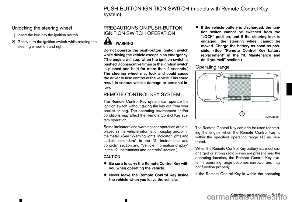
Operating range
The Remote Control Key can only be used for start-
ing the engine when the Remote Control Key is
within the specified operating range ➀as illus-
trated.
When the Remote Control Key battery is almost dis-
charged or strong radio waves are present near the
operating location, the Remote Control Key sys-
tem’s operating range becomes narrower and may
not function properly.
If the Remote Control Key is within the operating JVS0442XZ
PUSH-BUTTON IGNITION SWITCH (models with Remote Control Key
system)
Starting and driving5-15
Page 218 of 340
range, it is possible for anyone, even someone who
does not carry the Remote Control Key, to push the
ignition switch to start the engine.
• The cargo bed area is not included in the operat-
ing range of the engine start function.
• If the Remote Control Key is placed on the in-
strument panel, inside the glove box, door pocket
or the corner of the interior compartment, the
Remote Control Key may not function.
• If the Remote Control Key is placed near the
door or window outside the vehicle, the Remote
Control Key may function.
AUTOMATIC TRANSMISSION (AT)
The ignition lock is designed so that the ignition
switch cannot be switched to the “LOCK” position
until the shift lever is moved to the P(Park) position.
When pushing the ignition switch to the “OFF” posi-
tion, make sure the shift lever is in the P(Park) posi-
tion.
When the ignition switch cannot be switched to the
“LOCK” position:
1. [Shift to Park] warning appears on the vehicle
information display and achime sounds.
2. Move the shift lever to the P(Park) position.
3. If the ignition switch is in the “ACC” position, [PUSH] warning appears on the vehicle informa-
tion display.
4. Push the ignition switch. The ignition switch is switched to the “OFF” position. 5. Open the door. The ignition switch turns to the
“LOCK” position.
For warnings and indicators on the vehicle informa-
tion display, see “Indicators for operation” in the
“2. Instruments and controls” section.
If the ignition switch is switched to the “LOCK”
position, the shift lever cannot be moved from the P
(Park) position. The shift lever can be moved if the
ignition switch is in the “ON” position with the foot-
brake pedal depressed.
STEERING LOCK
The ignition switch is equipped with an anti-theft
steering lock device.
To lock steering wheel
1. Place the ignition switch in the “OFF” position where the ignition switch position indicator will
not illuminate.
2. Open or close the door. The ignition switch turns to the “LOCK” position.
3. Turn the steering wheel 1/6 of aturn to the right
or left from the straight up position.
To unlock steering wheel
Push the ignition switch, and the steering wheel will
be automatically unlocked.
CAUTION
• If the battery of the vehicle is discharged, the
push-button ignition switch cannot be
switched from the “LOCK” position. •
If the steering lock release malfunction indi-
cator (where fitted) appears in the vehicle in-
formation display, push the ignition switch
again while rotating the steering wheel slightly
to the right and left. (See “Vehicle information
display” in the “2. Instruments and controls”
section.)
IGNITION SWITCH POSITIONS WARNING
Never place the ignition switch in the “OFF” posi-
tion while driving. The steering wheel may lock
and cause the driver to lose control of the ve-
hicle, resulting in serious vehicle damage or per-
sonal injury.
CAUTION
• Do not leave the vehicle for extended periods
of time when the ignition switch is in the “ON”
position and the engine is not running. This
can discharge the battery.
• Use electrical accessories with the engine
running to avoid discharging the vehicle bat-
tery. If you must use accessories while the
engine is not running, do not use them for
extended periods of time and do not use mul-
tiple electrical accessories at the same time.
5-16 Starting and driving
Page 219 of 340
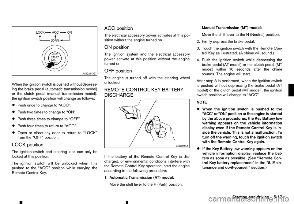
When the ignition switch is pushed without depress-
ing the brake pedal (automatic transmission model)
or the clutch pedal (manual transmission model),
the ignition switch position will change as follows:
• Push once to change to “ACC”.
• Push two times to change to “ON”.
• Push three times to change to “OFF”.
• Push four times to return to “ACC”.
• Open or close any door to return to “LOCK”
from the “OFF” position.
LOCK position
The ignition switch and steering lock can only be
locked at this position.
The ignition switch will be unlocked when it is
pushed to the “ACC” position while carrying the
Remote Control Key. ACC position
The electrical accessory power activates at this po-
sition without the engine turned on.
ON position
The ignition system and the electrical accessory
power activate at this position without the engine
turned on.
OFF position
The engine is turned off with the steering wheel
unlocked.
REMOTE CONTROL KEY BATTERY
DISCHARGE
If the battery of the Remote Control Key is dis-
charged, or environmental conditions interfere with
the Remote Control Key operation, start the engine
according to the following procedure:
1.
Automatic Transmission (AT) model:
Move the shift lever to the P(Park) position. Manual Transmission (MT) model:
Move the shift lever to the
N(Neutral) position.
2. Firmly depress the brake pedal.
3. Touch the ignition switch with the Remote Con- trol Key as illustrated. (A chime will sound.)
4. Push the ignition switch while depressing the brake pedal (AT model) or the clutch pedal (MT
model) within 10 seconds after the chime
sounds. The engine will start.
After step 3isperformed, when the ignition switch
is pushed without depressing the brake pedal (AT
model) or the clutch pedal (MT model), the ignition
switch position will change to “ACC”.
NOTE
• When the ignition switch is pushed to the
“ACC” or “ON” position or the engine is started
by the above procedures, the Key Battery low
warning appears on the vehicle information
display even if the Remote Control Key is in-
side the vehicle. This is not
amalfunction. To
turn off the warning, touch the ignition switch
with the Remote Control Key again.
• If the Key Battery low warning appears on the
vehicle information display, replace the bat-
tery as soon as possible. (See “Remote Con-
trol Key battery replacement” in the “8. Main-
tenance and do-it-yourself” section.) JVS0241XZ
SSD0944Z
Starting and driving
5-17
Page 220 of 340
1. Apply the parking brake.
2. Depress the footbrake pedal.
3. Automatic Transmission (AT) model:
Move the shift lever to the P(Park) or the N(Neu-
tral) position.
The starter is designed to operate only when
the shift lever is in the proper position.
Manual Transmission (MT) model:
Move the shift lever to the N(Neutral) position
and depress the clutch pedal to the floor while
starting the engine.
4. Crank the engine with your foot off the accelera- tor pedal by turning the ignition switch to the
For diesel engine models: Turn the ignition
switch to the
glow plug indicator light turns off.
5. Immediately release the ignition switch when the engine starts. If the engine starts, but fails to run,
repeat the above procedures.
6. Allow the engine to idle for at least 30 seconds after starting the engine to warm-up. Drive at
moderate speeds for ashort distance first, espe-
cially in cold weather.
CAUTION
Do not leave the vehicle unattended while the
engine is warming up. 1. Apply the parking brake.
2.
Automatic Transmission (AT) model:
Move the shift lever to the P(Park) or the N(Neu-
tral) position.
The starter is designed to operate only when
the shift lever is in the proper position.
Manual Transmission (MT) model:
Move the shift lever to the N(Neutral) position.
The Remote Control Key must be carried when operating the ignition switch.
3. Place the ignition switch in the “ON” position. Depress the brake pedal (AT model) or the clutch
pedal (MT model) and push the ignition switch to
start the engine.
For diesel engine models: Wait until the glow
plug indicator light goes out.
To start the engine immediately, push and re-
lease the ignition switch while depressing the
brake pedal or clutch pedal with the ignition
switch in any position.
4. Immediately release the ignition switch when the engine starts. If the engine starts, but fails to run,
repeat the above procedures.
5. Allow the engine to idle for at least 30 seconds after starting the engine to warm-up. Drive at
moderate speeds for ashort distance first, espe-
cially in cold weather. CAUTION
Do not leave the vehicle unattended while the
engine is warming up.
6. To stop the engine, move the shift lever to the P (Park) (AT model) or N(Neutral) (MT model) po-
sition, apply the parking brake, and push the igni-
tion switch to the “OFF” position.
STARTING ENGINE (models
without Remote Control Key system)
STARTING ENGINE (models with
Remote Control Key system)
5-18 Starting and driving