diagram RENAULT KANGOO 1997 KC / 1.G Chassis Workshop Manual
[x] Cancel search | Manufacturer: RENAULT, Model Year: 1997, Model line: KANGOO, Model: RENAULT KANGOO 1997 KC / 1.GPages: 105
Page 3 of 105
Contents
Page
Chassis
GENERAL
General diagram of braking circuits
Tightening torques (in daN.m)
Dimensions of the main braking
components
Bar specifications:
- front anti-roll bar
- rear anti-roll bar
- rear suspension bars
Brake unions and pipes
Brake fluid30
30-1
30-2
30-7
30-8
30-8
30-8
30-9
30-9
31-1
31-2
31-3
31-4
31-5
31-6
31-7
31-9
31-10
31-12
ENSEMBLE MOTEUR ET BAS
Lower wishbone
Lower wishbone rubber bushes
Lower wishbone ball joint
Brake pads
Front brake calipers
Brake discs
Stub axle carrier bearing
Spring and shock absorber assembly
Anti-roll bar
Engine sub-frameFRONT AXLE31
35-1
35-4Specifications
Wheel balancing
WHEELS AND TYRES35
33-1
33-2
33-4
33-5
33-7
33-8
33-9
33-10
33-11
33-15
33-16
33-20Rear axle assembly
Brake drum
Brake cylinder
Brake linings (drum)
Bearing
Shock absorber
Anti-roll bar, tubular rear axle
Half suspension arms, tubular rear
axle
Bushes, tubular rear axle
Suspension bars, tubular rear axle
Four bar rear axle
Suspension arm bearings
REAR AXLE33
Page 4 of 105
Master cylinder
Brake servo
Air filter - Brake servo non-return
valve
Vacuum pump
Handbrake control lever
Handbrake control
Brake pipes
Braking compensator
Clutch control cable
Clutch automatic wear take-up
system
External gear control37-1
37-3
37-5
37-6
37-7
37-8
37-10
37-11
37-22
37-23
37-24
Contents
Page
MECHANICAL ELEMENT CONTROLS37
38-1
38-2
38-3
38-4
38-5
38-6
38-7
38-8
38-9
BOSCH ABS
Presentation of BOSCH ABS 5.3
Location of components
Presentation of the hydraulic
regulation assembly
Wiring diagram
Wiring diagram key
31 track connector
Diagnostic socket
Hydraulic assembly
Hydraulic braking test
ELECTRONICALLY CONTROLLED
HYDRAULIC SYSTEMS38STEERING ASSEMBLY
Axial ball joint
Manual steering rack
Power assisted steering rack
Gaiter
Steering rack pinion
Manual steering assistance pump
Steering column
36-1
36-3
36-4
36-6
36-7
36-8
36-12
36
Page 5 of 105
91563S
GENERAL
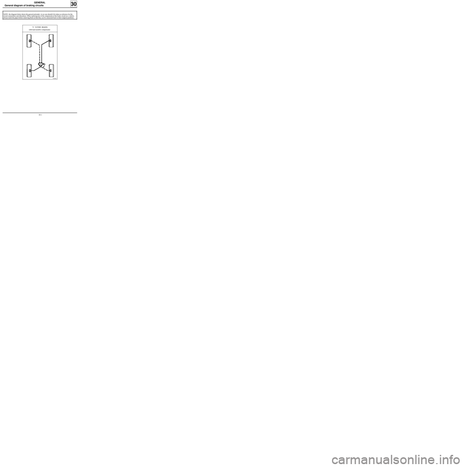
General diagram of braking circuits
30
NOTE : the diagram below shows the general principle ; in no case should it be taken as reference for the
circuit connections and allocations. When replacing one of the components of the brake circuit on a vehicle,
always mark the pipes before removing them so that they can be connected back in their original positions.
"X" PATTERN BRAKING
with load sensitive compensator
30-1
Page 39 of 105
REAR AXLE
Bushes, tubular rear axle
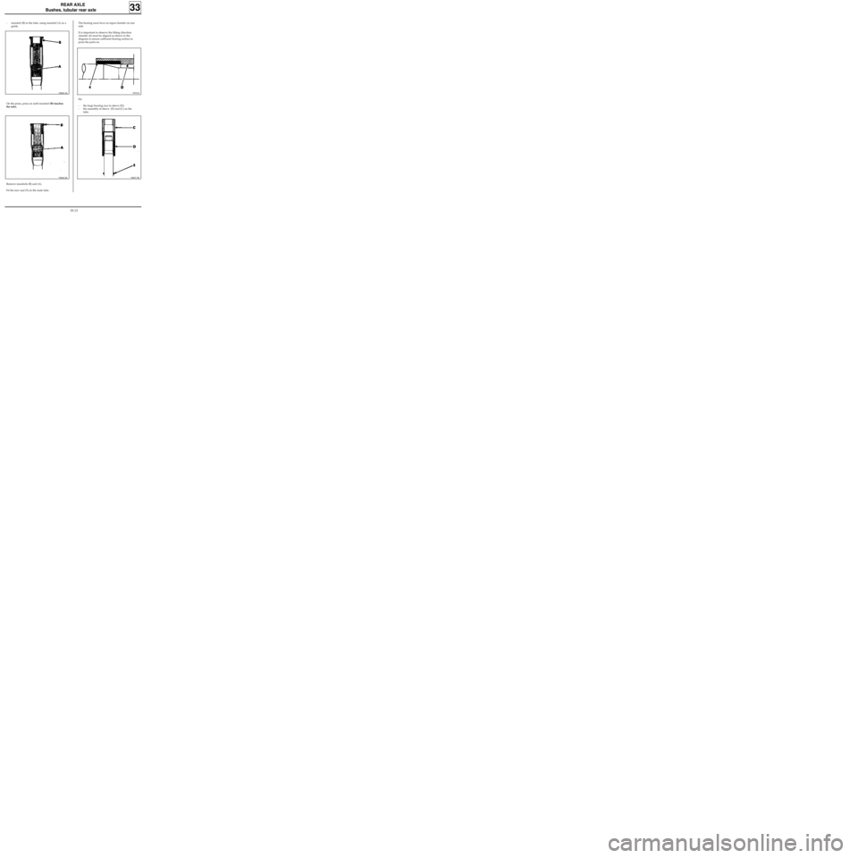
- mandrel (B) in the tube, using mandrel (A) as a
guide.
33
On the press, press on until mandrel (B) touches
the tube.
Remove mandrels (B) and (A).
Fit the new seal (5) on the male tube.
The bearing races have an input chamfer on one
side.
It is important to observe the fitting direction:
chamfer (4) must be aligned as shown in the
diagram to ensure sufficient bearing surface to
press the parts on.
Fit:
- the large bearing race in sleeve (D),
- the assembly of sleeve (D) and (C) on the
tube.
90868-1R90941R
90868-2R90867-5R
33-13
Page 43 of 105
REAR AXLE
Four bar rear axle
SPECIAL TOOLING REQUIRED
Emb. 880 Inertia extractor
TIGHTENING TORQUES (in daN.m)
Upper shock absorber mounting 8.5
Lower shock absorber mounting 11.5
Wheel bolts 9
REMOVAL
Remove:
- the wheels,
- the shock absorbers,
- the suspension bar plugs.
Remove using tool Emb. 880 :
- the two suspension bars,
- the two anti-roll bars, retaining the central
shackle.
Clean and lubricate the bar splines using
MOLYKOTE BR2.
REFITTING
The anti-roll bars cannot be removed from the
vehicle when the shock absorber replacement tool
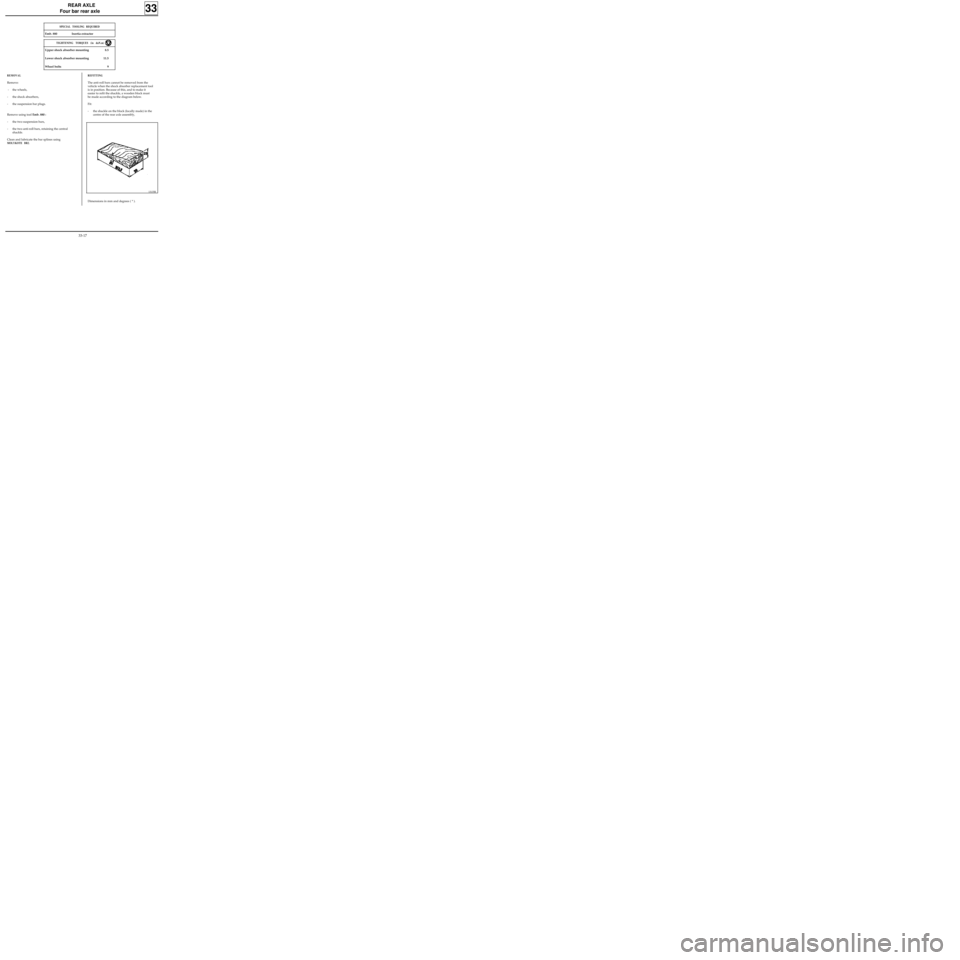
is in position. Because of this, and to make it
easier to refit the shackle, a wooden block must
be made according to the diagram below.
Fit:
- the shackle on the block (locally made) in the
centre of the rear axle assembly,
33
13135R
Dimensions in mm and degrees ( ° ).
33-17
Page 73 of 105
83 212
75 564
MECHANICAL ELEMENT CONTROLS
Air filter - Brake servo non-return valve
REPLACING THE AIR FILTER
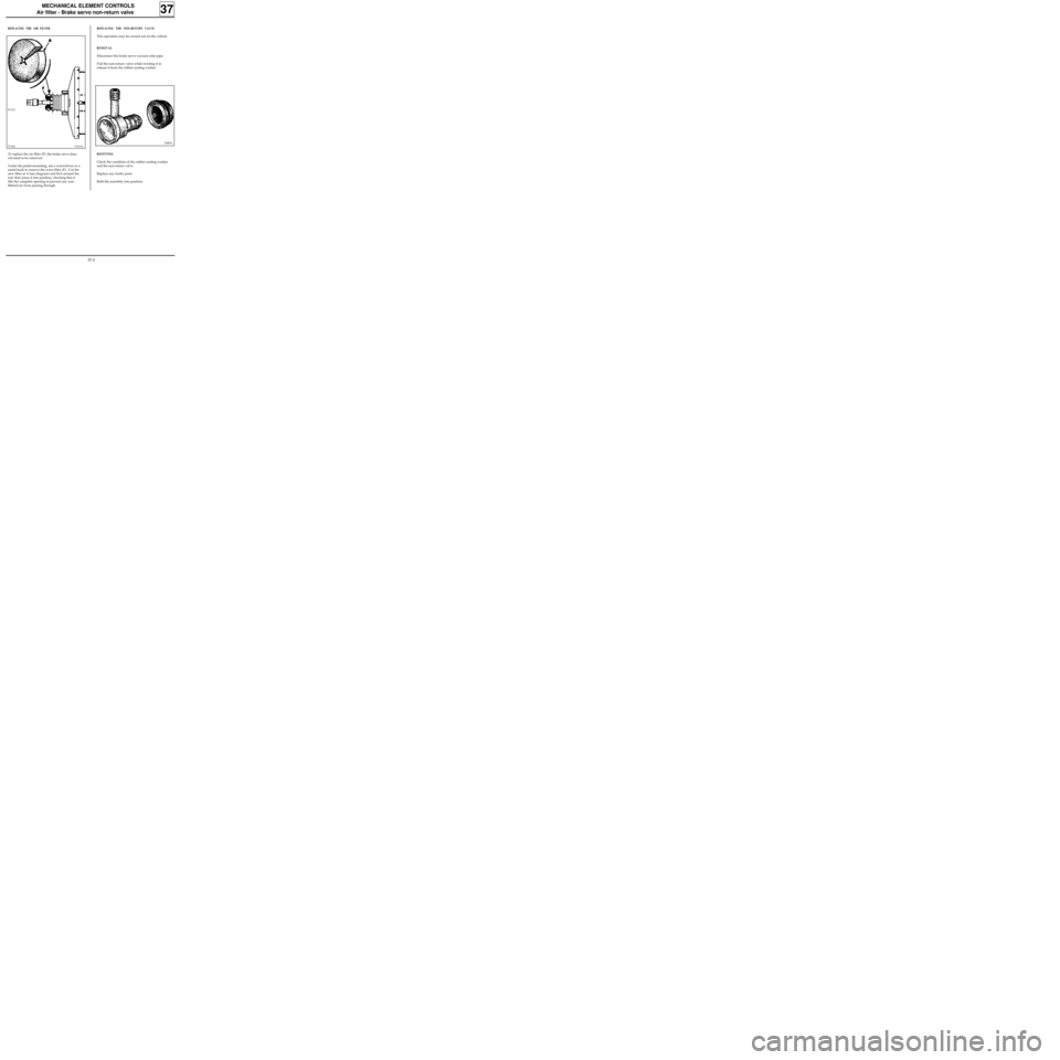
To replace the air filter (F), the brake servo does
not need to be removed.
Under the pedal mounting, use a screwdriver or a
metal hook to remove the worn filter (F). Cut the
new filter at A (see diagram) and fit it around the
rod, then press it into position, checking that it
fills the complete opening to prevent any non-
filtered air from passing through.
REPLACING THE NON-RETURN VALVE
This operation may be carried out on the vehicle.
REMOVAL
Disconnect the brake servo vacuum inlet pipe.
Pull the non-return valve while twisting it to
release it from the rubber sealing washer.
REFITTING
Check the condition of the rubber sealing washer
and the non-return valve.
Replace any faulty parts.
Refit the assembly into position.
37
91101G74883S
37-5
Page 99 of 105
ELECTRONICALLY CONTROLLED HYDRAULIC SYSTEMS
BOSCH ABS
38
PRN3817
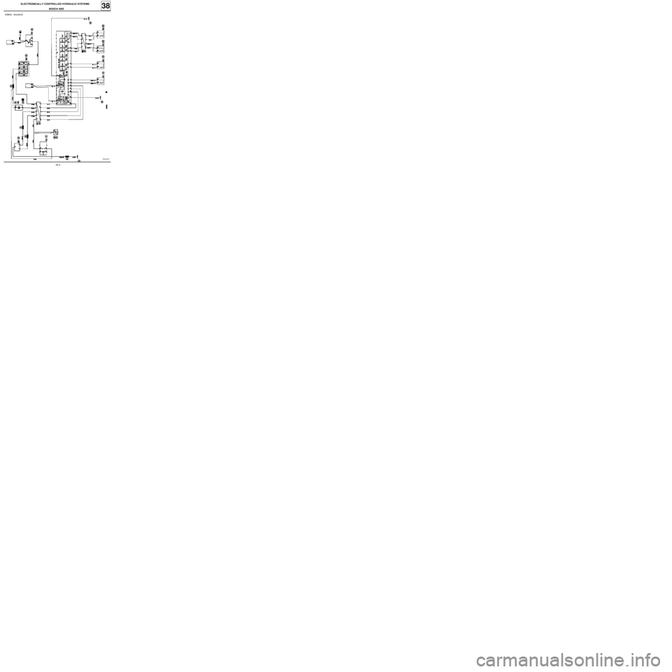
WIRING DIAGRAM
38-4
Page 100 of 105
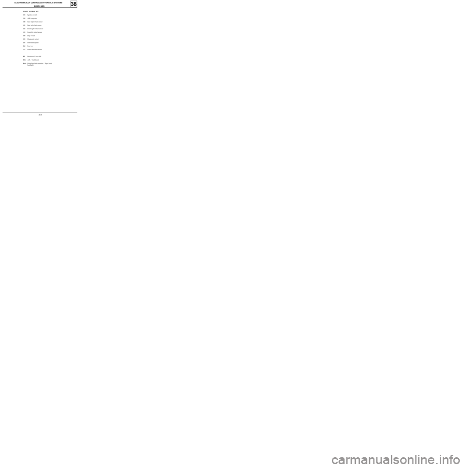
WIRING DIAGRAM KEY
104Ignition switch
118 ABS computer
150Rear right wheel sensor
151Rear left wheel sensor
152Front right wheel sensor
153Front left wheel sensor
160Stop switch
225Diagnostic socket
247Instrument panel
260Fuse box
777Power feed fuse board
R2Dashboard / rear left
R36ABS / Dashboard
R101Right hand side member / Right hand
headlight
ELECTRONICALLY CONTROLLED HYDRAULIC SYSTEMS
BOSCH ABS
38
38-5