engine RENAULT KANGOO 1997 KC / 1.G Chassis Workshop Manual
[x] Cancel search | Manufacturer: RENAULT, Model Year: 1997, Model line: KANGOO, Model: RENAULT KANGOO 1997 KC / 1.GPages: 105
Page 3 of 105
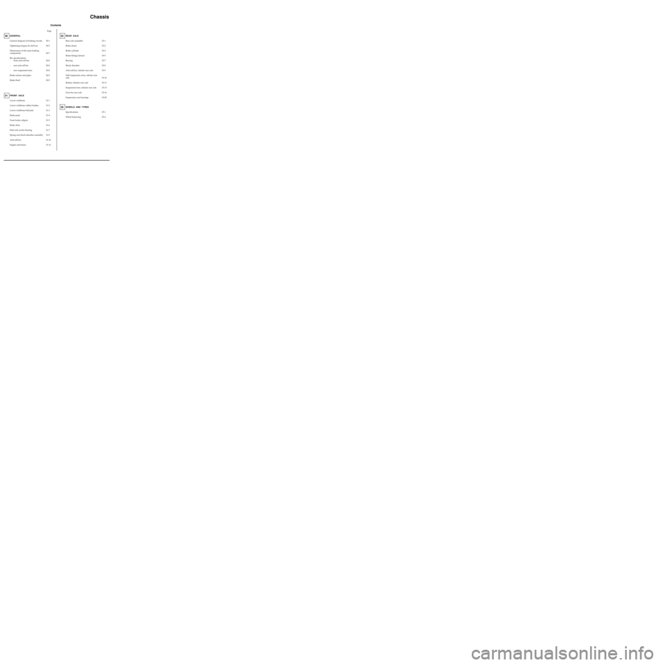
Contents
Page
Chassis
GENERAL
General diagram of braking circuits
Tightening torques (in daN.m)
Dimensions of the main braking
components
Bar specifications:
- front anti-roll bar
- rear anti-roll bar
- rear suspension bars
Brake unions and pipes
Brake fluid30
30-1
30-2
30-7
30-8
30-8
30-8
30-9
30-9
31-1
31-2
31-3
31-4
31-5
31-6
31-7
31-9
31-10
31-12
ENSEMBLE MOTEUR ET BAS
Lower wishbone
Lower wishbone rubber bushes
Lower wishbone ball joint
Brake pads
Front brake calipers
Brake discs
Stub axle carrier bearing
Spring and shock absorber assembly
Anti-roll bar
Engine sub-frameFRONT AXLE31
35-1
35-4Specifications
Wheel balancing
WHEELS AND TYRES35
33-1
33-2
33-4
33-5
33-7
33-8
33-9
33-10
33-11
33-15
33-16
33-20Rear axle assembly
Brake drum
Brake cylinder
Brake linings (drum)
Bearing
Shock absorber
Anti-roll bar, tubular rear axle
Half suspension arms, tubular rear
axle
Bushes, tubular rear axle
Suspension bars, tubular rear axle
Four bar rear axle
Suspension arm bearings
REAR AXLE33
Page 22 of 105
Spring compressor
FRONT AXLE
Spring and shock absorber assembly
31
Shock absorber base mounting bolt 18
Rebound stop nut 6
Wheel bolts 9
REMOVAL
Put the vehicle on a four post lift.
Remove:
- the wheels,
- the shock absorber base mounting bolts.
NOTE : release the ABS sensor wiring if this is
fitted on the base of the shock absorber.
Remove the upper shock absorber nut in the
engine compartment.
Remove the shock absorber and spring assembly.
TIGHTENING TORQUES (in daN.m)
EQUIPMENT REQUIRED
Replacing a shock absorber
When replacing a shock absorber, fit it in a vice
and compress the spring using the spring
compressor tool.
Remove the spring retaining nut.
Remove the spring and the intermediate parts.
If necessary, replace the shock absorber pad and
the rotating stop.
When refitting, ensure all components are
replaced in the correct location and then
decompress the spring.
NOTE : apply grease between the ends of the
spring and its stops.
REFITTING
Refitting is then the reverse of removal. Observe
the correct tightening torques.
31-9
Page 25 of 105
FRONT AXLE
Engine sub-frame
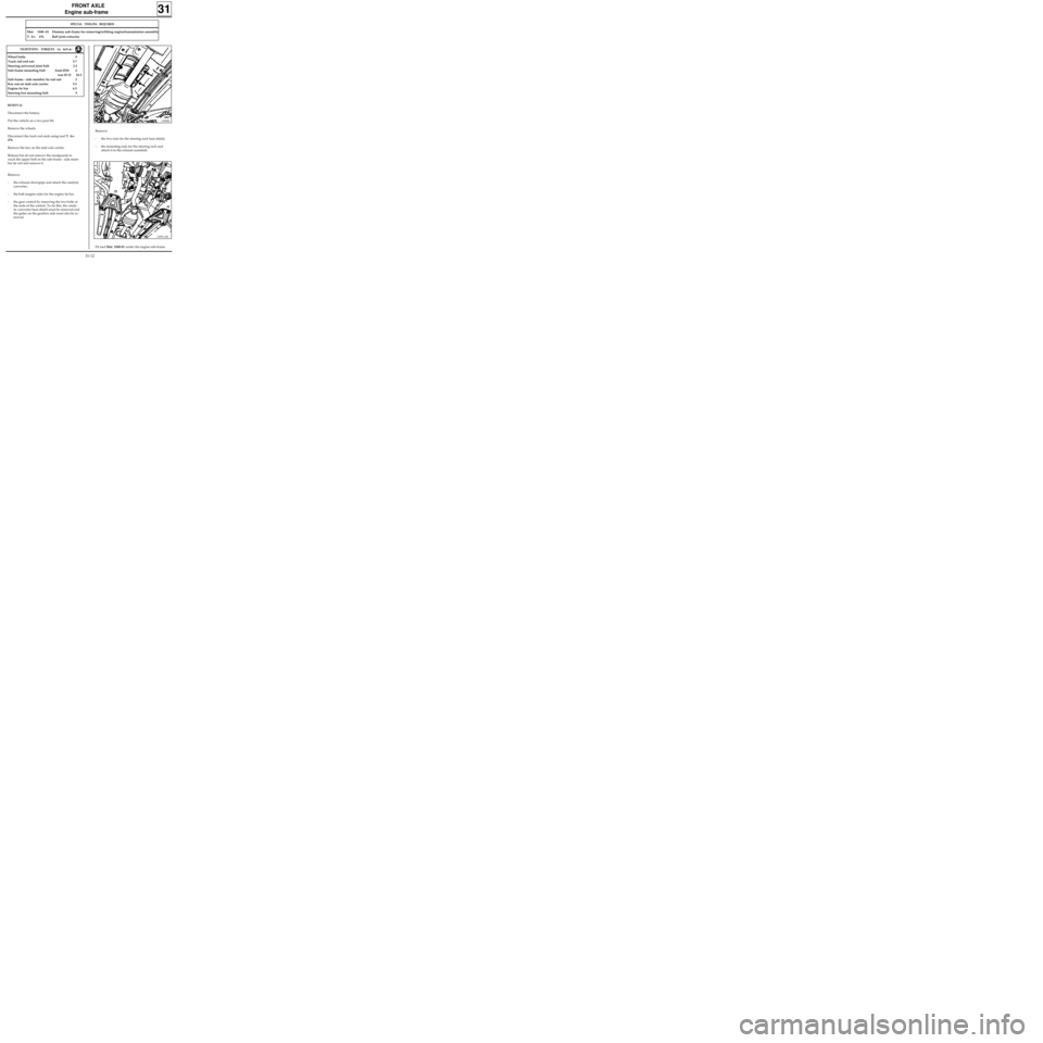
Remove:
- the two nuts for the steering rack heat shield,
- the mounting nuts for the steering rack and
attach it to the exhaust manifold.
31
12988R
SPECIAL TOOLING REQUIRED
Mot. 1040 -01 Dummy sub-frame for removing/refitting engine/transmission assembly
T. Av. 476 Ball joint extractor
REMOVAL
Disconnect the battery.
Put the vehicle on a two post lift.
Remove the wheels.
Disconnect the track rod ends using tool T. Av.
476.
Remove the key on the stub axle carrier.
Release but do not remove the mudguards to
reach the upper bolt on the sub-frame - side mem-
ber tie rod and remove it.
Remove:
- the exhaust downpipe and attach the catalytic
converter,
- the bolt (engine side) for the engine tie bar.
- the gear control by removing the two bolts at
the ends of the control. To do this, the cataly-
tic converter heat shield must be removed and
the gaiter on the gearbox side must also be re-
moved.
TIGHTENING TORQUES (in daN.m)
Wheel bolts 9
Track rod end nut 3.7
Steering universal joint bolt 2.5
Sub-frame mounting bolt front Ø10 6
rear Ø 12 10.5
Sub-frame - side member tie rod nut 3
Key nut on stub axle carrier 5.5
Engine tie bar 6.5
Steering box mounting bolt 5
Fit tool Mot. 1040-01 under the engine sub-frame.
12993-1R1
31-12
Page 26 of 105
FRONT AXLE
Engine sub-frame
31
Lower the lift until the tool touches the ground.
Remove the sub-frame mounting bolts.
Carefully raise the lift.
REFITTING
Systematically renew the engine sub-frame moun-
ting bolts and ensure they are tightened to the
correct torque.
Refitting is the reverse of removal.
NOTE : the engine sub-frame is fitted to the body
in the following manner.:
- fit 2 pins in place of the front mounting bolts,
- offer up the sub-frame,
- tighten, but do not lock, the rear mounting
bolts (begin with the longest rear right hand
bolt),
- replace the pins with mounting bolts at the
front,
- tighten the four mounting bolts to the correct
torque, beginning at the rear,
- ensure the heat shields are correctly refitted.
31-13
Page 56 of 105
STEERING ASSEMBLY
Power assisted steering rack
36
SPECIAL TOOLING REQUIRED
Mot. 453-01 Hose clamp pliers
T.Av. 476 Ball joint extractor
Wheel bolts 9
Track rod end nut 3.7
Steering rack mounting bolt 5
Universal joint eccentric bolt 2.5
Engine tie bar bolt 6.5
TIGHTENING TORQUES (in daN.m)
Put the vehicle on a two post lift.
REMOVAL
Remove the front wheels.
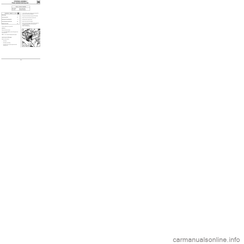
Fit a clamp Mot. 453-01 to each of the pipes from
the oil reservoir.
NOTE :never clamp the high pressure pipes.
Cut the rubber gaiter retaining clip and push the
gaiter back towards the bulkhead.
Disconnect the ball joints using tool T.Av. 476.
Remove the universal joint eccentric bolt.
Disconnect the oxygen sensor.
Remove the exhaust downpipe.
Remove the bolt (engine side) from the engine tie
bar and pivot the engine and transmission
assembly forwards.
Insert a retaining block.
Special notes for F8Q engine
Remove (from above) :
- the battery,
- the battery mounting,
- the high and low pressure pipes from the
steering valve.
13120S
36-4
Page 57 of 105
STEERING ASSEMBLY
Power assisted steering rack
36
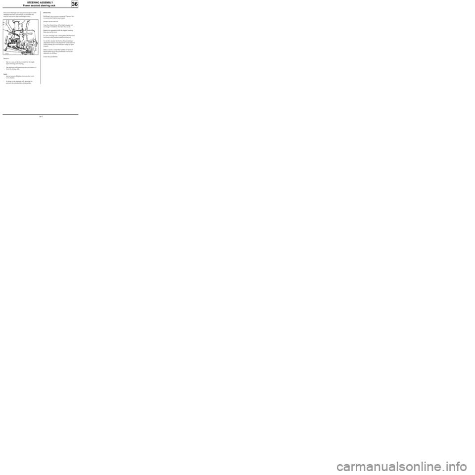
Disconnect the high and low pressure pipes on the
steering rack (take precautions to catch the oil)
and the nut on the pipe retaining bracket.
Remove:
- the two nuts on the heat shield for the right
hand steering rack bearing,
- the steering rack mounting nuts and remove it
from the timing side.
NOTE :
- do not remove the pipes between the valve
and cylinder,
- fit plugs to the steering rack openings to
prevent the introduction of impurities.
12997R
REFITTING
Refitting is the reverse of removal. Observe the
recommended tightening torques.
Fill the circuit with oil.
Turn the wheels from left to right (engine not
running) to distribute the oil in the circuit.
Repeat the operation with the engine running
then top up the level.
If a new steering rack is being fitted, fit the track
rod ends in the position noted on removal.
To do this, slacken the bolt on the parallelism
adjustment sleeve and slacken the track rod end
while holding the axial ball joint using an open
wrench.
Make a mark or count the number of turns of
thread taken up so the parallelism can be pre-
adjusted on refitting.
Check the parallelism.
36-5
Page 60 of 105
STEERING ASSEMBLY
Manual steering assistance pump
36
SPECIAL TOOLING REQUIRED
Dir. 1083Tool for refitting the PAS pump
pulley
B.Vi. 22-01
+Tool for removing the PAS pump
pulley
B.Vi. 47
12996R
REPLACING THE PULLEY (D7F-F8Q engine without
AC)
REMOVAL
Remove:
- the PAS pump belt.
- the pulley (three bolts).
REFITTING
Refitting is the reverse of removal. Observe the
procedure for tensioning the belt (see section 07).
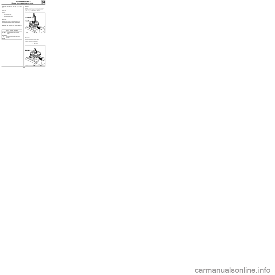
REPLACING THE PULLEY ( E7J engine without AC)
REMOVAL
With the pump removed (see removal method on
following pages), set it in a vice and extract the
pulley using tools B.Vi. 22-01 + B.Vi. 47.
12995R
REFITTING
Refit the pulley using tool Dir. 1083.
Press the pulley on to dimension:
X =34.7 ± 0.2
36-8
Page 61 of 105
STEERING ASSEMBLY
Manual steering assistance pump
36
SPECIAL TOOLING REQUIRED
Mot. 453-01Hose clamp pliers
T. Ar. 1094Extractor
Put the vehicle on a two post lift.
REMOVAL
Remove:
- the PAS pump belt,
- the pulley.
Fit a clamp Mot. 453-01 to the supply pipe.
Disconnect the supply and high pressure pipes.
Take precautions to catch the PAS fluid (protect
the alternator).
Remove the three pump mounting bolts and
remove the pump.
REFITTING
Refitting is the reverse of removal. Observe the
procedure for tensioning the belt (see section 07).
Fill and bleed the circuit, moving the steering
from lock to lock.
D7F engine
without AC
36-9
Page 62 of 105
STEERING ASSEMBLY
Manual steering assistance pump
36
SPECIAL TOOLING REQUIRED
Mot. 453-01Hose clamp pliers
Put the vehicle on a two post lift.
REMOVAL
Remove:
- the right hand wheel,
- the right hand mudguard,
- the bumper (10 bolts).
- the accessories belt,
- the pulley.
Fit a clamp Mot. 453-01 to the supply pipe.
Disconnect the supply and high pressure pipes.
Take precautions to catch the PAS fluid.
Remove the three pump mounting bolts and
remove the pump.
REFITTING
Refitting is the reverse of removal. Observe the
procedure for tensioning the belt (see section 07).
Fill and bleed the circuit, moving the steering
from lock to lock.
F8Q engine
without AC
36-10
Page 63 of 105
STEERING ASSEMBLY
Manual steering assistance pump
36
SPECIAL TOOLING REQUIRED
Mot. 453-01Hose clamp pliers
Put the vehicle on a two post lift.
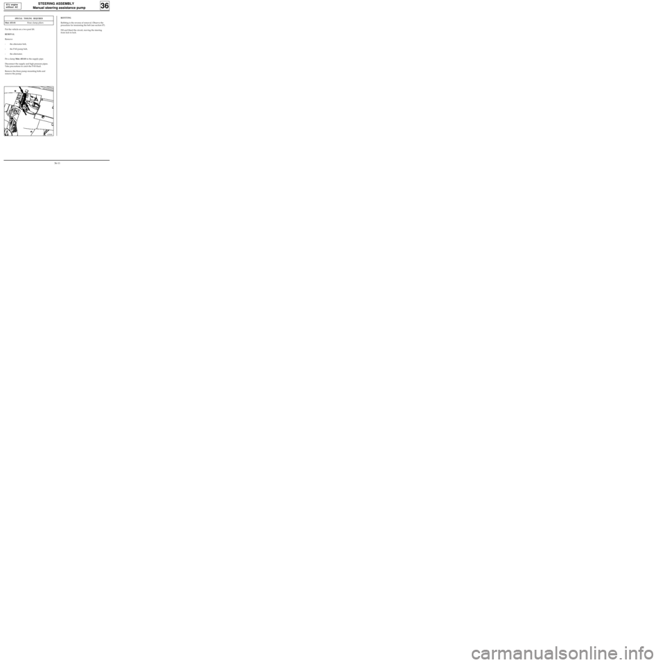
REMOVAL
Remove:
- the alternator belt,
- the PAS pump belt,
- the alternator.
Fit a clamp Mot. 453-01 to the supply pipe.
Disconnect the supply and high pressure pipes.
Take precautions to catch the PAS fluid.
Remove the three pump mounting bolts and
remove the pump.
REFITTING
Refitting is the reverse of removal. Observe the
procedure for tensioning the belt (see section 07).
Fill and bleed the circuit, moving the steering
from lock to lock.
13296R
E7J engine
without AC
36-11