key RENAULT KANGOO 1997 KC / 1.G Chassis Workshop Manual
[x] Cancel search | Manufacturer: RENAULT, Model Year: 1997, Model line: KANGOO, Model: RENAULT KANGOO 1997 KC / 1.GPages: 105
Page 4 of 105

Master cylinder
Brake servo
Air filter - Brake servo non-return
valve
Vacuum pump
Handbrake control lever
Handbrake control
Brake pipes
Braking compensator
Clutch control cable
Clutch automatic wear take-up
system
External gear control37-1
37-3
37-5
37-6
37-7
37-8
37-10
37-11
37-22
37-23
37-24
Contents
Page
MECHANICAL ELEMENT CONTROLS37
38-1
38-2
38-3
38-4
38-5
38-6
38-7
38-8
38-9
BOSCH ABS
Presentation of BOSCH ABS 5.3
Location of components
Presentation of the hydraulic
regulation assembly
Wiring diagram
Wiring diagram key
31 track connector
Diagnostic socket
Hydraulic assembly
Hydraulic braking test
ELECTRONICALLY CONTROLLED
HYDRAULIC SYSTEMS38STEERING ASSEMBLY
Axial ball joint
Manual steering rack
Power assisted steering rack
Gaiter
Steering rack pinion
Manual steering assistance pump
Steering column
36-1
36-3
36-4
36-6
36-7
36-8
36-12
36
Page 14 of 105
FRONT AXLE
Lower wishbone
31
85875R2
12992R
Wheel bolts 9
Lower wishbone nut on sub-frame 9
Key nut on stub-axle carrier 5.5
Anti-roll bar bearing nut 1.5
TIGHTENING TORQUES (in daN.m)
REMOVAL
Put the vehicle on a two post lift.
Remove both wheels.
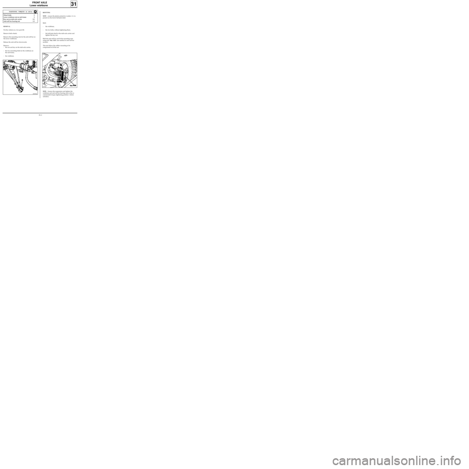
Remove the mounting nuts for the anti-roll bar on
the lower wishbones.
Release the anti-roll bar downwards.
Remove:
- the nut and key on the stub-axle carrier,
- the two mounting bolts for the wishbone on
the sub-frame,
- the wishbone.
REFITTING
NOTE :
ensure the plastic protective washer ( A ) is
present on the lower ball joint shaft.
Refit:
- the wishbone,
- the two bolts, without tightening them,
- the ball joint shaft in the stub-axle carrier and
tighten the key nut.
Refit the anti-roll bar and fit the mounting nuts
using tool Sus. 1414 (see method in anti-roll bar
section).
This tool allows the rubber mounting to be
compressed to fit the nut.
NOTE : bounce the suspension and tighten the
wishbone and anti-roll bar bearing nuts to the re-
commended torque (tightening position: vehicle
unladen).
31-1
Page 20 of 105
FRONT AXLE
Stub axle carrier bearing
31
SPECIAL TOOLING REQUIRED
Rou. 15 -01 Shaft protector
Rou. 604 -01 Hub locking tool
T.Av.476 Ball joint extractor
T.Av. 1050-02 Tool for pushing driveshaft back
Driveshaft nut 28
Wheel bolts 9
Shock absorber base nut 18
Brake caliper mounting bolt 10
Track rod end nut 3.7
Key nut on stub axle carrier 5.5
83348G
REMOVAL
Disconnect the battery.
Remove:
- the wheel,
- the brake caliper and attach it to the spring so
the pipe is not damaged,
- the track rod end using tool
T.Av. 476,
- the driveshaft nut.
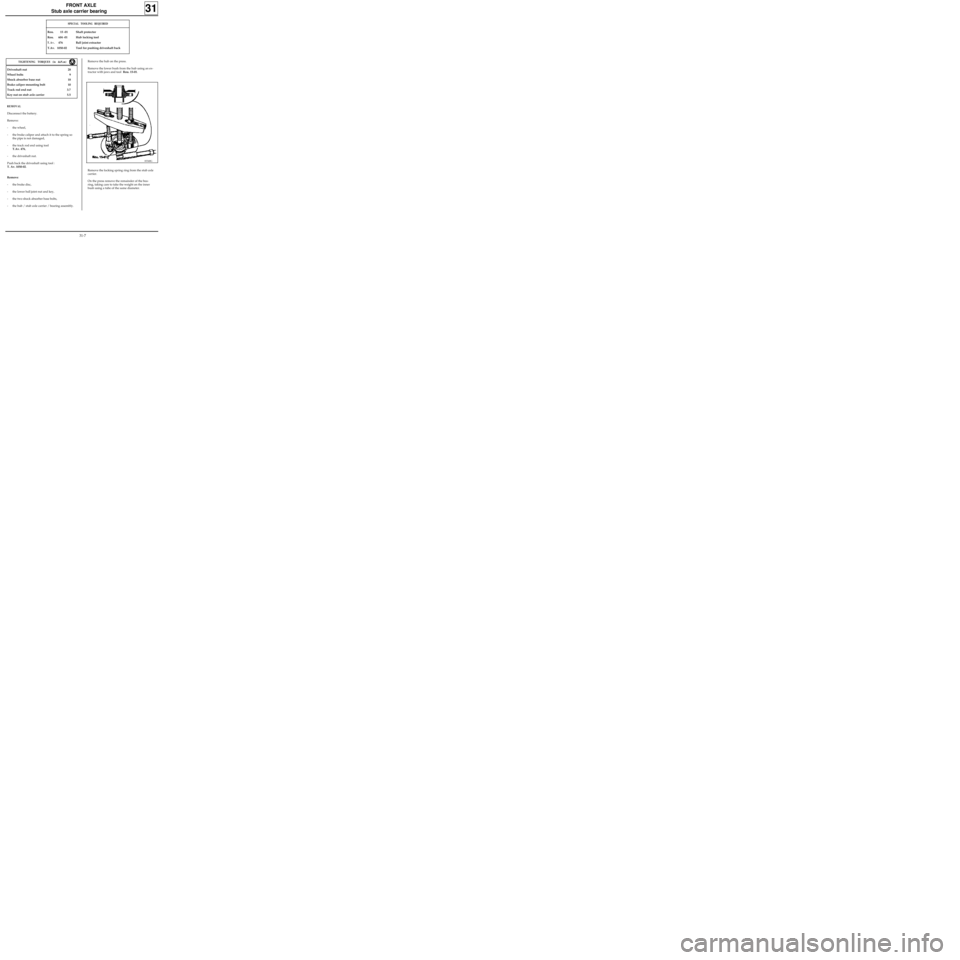
Push back the driveshaft using tool :
T. Av. 1050-02.
Remove:
- the brake disc,
- the lower ball joint nut and key,
- the two shock absorber base bolts,
- the hub / stub axle carrier / bearing assembly.
TIGHTENING TORQUES (in daN.m)Remove the hub on the press.
Remove the lower bush from the hub using an ex-
tractor with jaws and tool Rou. 15-01.
Remove the locking spring ring from the stub axle
carrier.
On the press remove the remainder of the bea-
ring, taking care to take the weight on the inner
bush using a tube of the same diameter.
31-7
Page 25 of 105
FRONT AXLE
Engine sub-frame
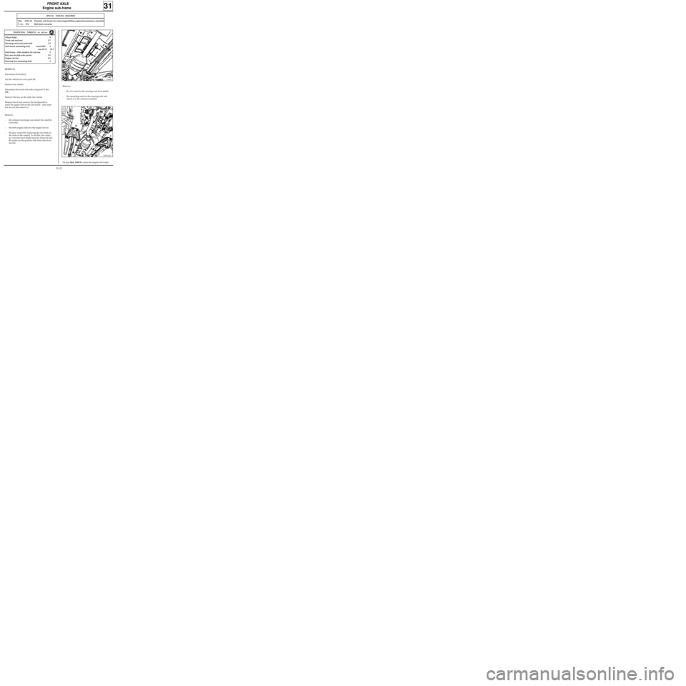
Remove:
- the two nuts for the steering rack heat shield,
- the mounting nuts for the steering rack and
attach it to the exhaust manifold.
31
12988R
SPECIAL TOOLING REQUIRED
Mot. 1040 -01 Dummy sub-frame for removing/refitting engine/transmission assembly
T. Av. 476 Ball joint extractor
REMOVAL
Disconnect the battery.
Put the vehicle on a two post lift.
Remove the wheels.
Disconnect the track rod ends using tool T. Av.
476.
Remove the key on the stub axle carrier.
Release but do not remove the mudguards to
reach the upper bolt on the sub-frame - side mem-
ber tie rod and remove it.
Remove:
- the exhaust downpipe and attach the catalytic
converter,
- the bolt (engine side) for the engine tie bar.
- the gear control by removing the two bolts at
the ends of the control. To do this, the cataly-
tic converter heat shield must be removed and
the gaiter on the gearbox side must also be re-
moved.
TIGHTENING TORQUES (in daN.m)
Wheel bolts 9
Track rod end nut 3.7
Steering universal joint bolt 2.5
Sub-frame mounting bolt front Ø10 6
rear Ø 12 10.5
Sub-frame - side member tie rod nut 3
Key nut on stub axle carrier 5.5
Engine tie bar 6.5
Steering box mounting bolt 5
Fit tool Mot. 1040-01 under the engine sub-frame.
12993-1R1
31-12
Page 100 of 105

WIRING DIAGRAM KEY
104Ignition switch
118 ABS computer
150Rear right wheel sensor
151Rear left wheel sensor
152Front right wheel sensor
153Front left wheel sensor
160Stop switch
225Diagnostic socket
247Instrument panel
260Fuse box
777Power feed fuse board
R2Dashboard / rear left
R36ABS / Dashboard
R101Right hand side member / Right hand
headlight
ELECTRONICALLY CONTROLLED HYDRAULIC SYSTEMS
BOSCH ABS
38
38-5