sensor RENAULT KANGOO 1997 KC / 1.G Chassis Workshop Manual
[x] Cancel search | Manufacturer: RENAULT, Model Year: 1997, Model line: KANGOO, Model: RENAULT KANGOO 1997 KC / 1.GPages: 105
Page 22 of 105
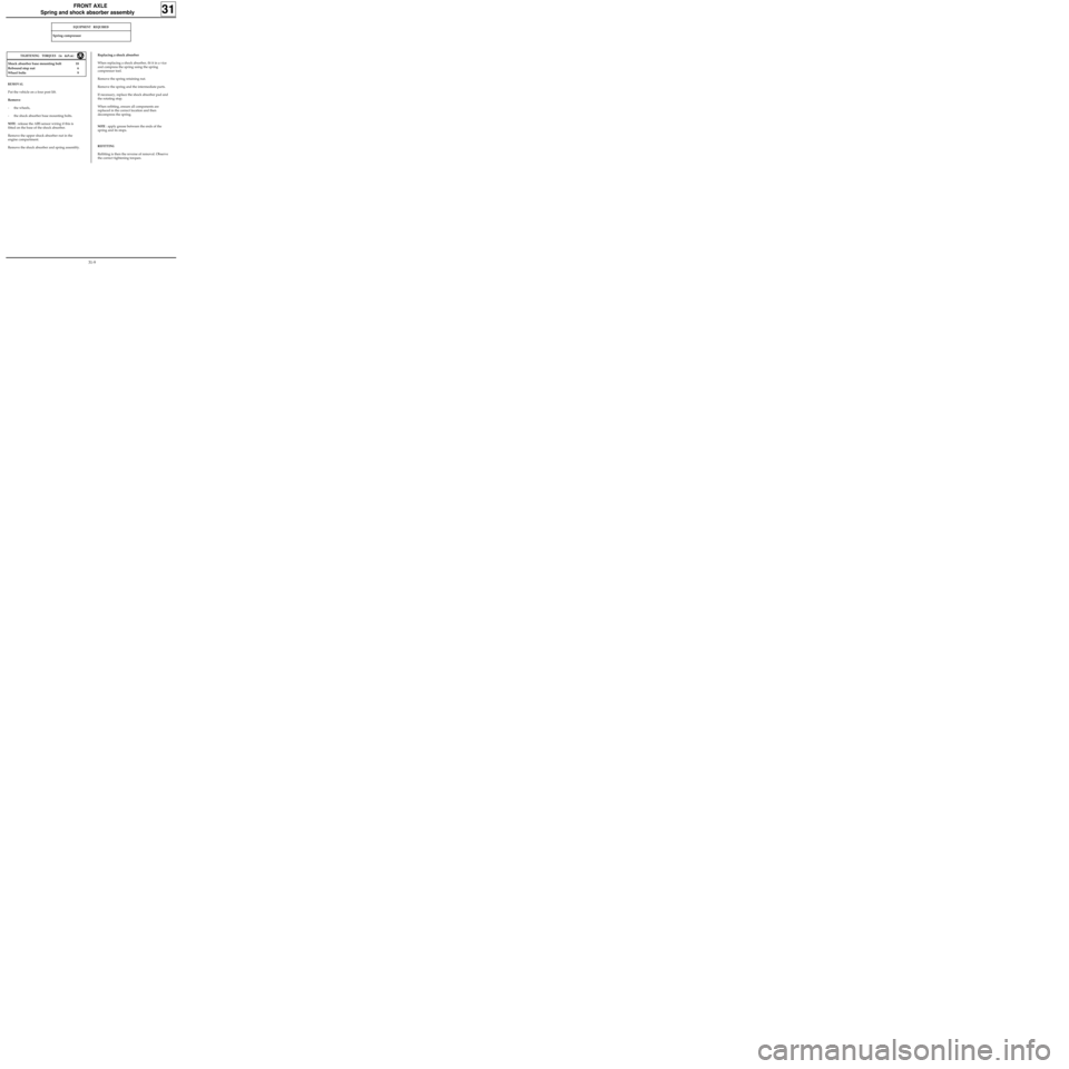
Spring compressor
FRONT AXLE
Spring and shock absorber assembly
31
Shock absorber base mounting bolt 18
Rebound stop nut 6
Wheel bolts 9
REMOVAL
Put the vehicle on a four post lift.
Remove:
- the wheels,
- the shock absorber base mounting bolts.
NOTE : release the ABS sensor wiring if this is
fitted on the base of the shock absorber.
Remove the upper shock absorber nut in the
engine compartment.
Remove the shock absorber and spring assembly.
TIGHTENING TORQUES (in daN.m)
EQUIPMENT REQUIRED
Replacing a shock absorber
When replacing a shock absorber, fit it in a vice
and compress the spring using the spring
compressor tool.
Remove the spring retaining nut.
Remove the spring and the intermediate parts.
If necessary, replace the shock absorber pad and
the rotating stop.
When refitting, ensure all components are
replaced in the correct location and then
decompress the spring.
NOTE : apply grease between the ends of the
spring and its stops.
REFITTING
Refitting is then the reverse of removal. Observe
the correct tightening torques.
31-9
Page 56 of 105
STEERING ASSEMBLY
Power assisted steering rack
36
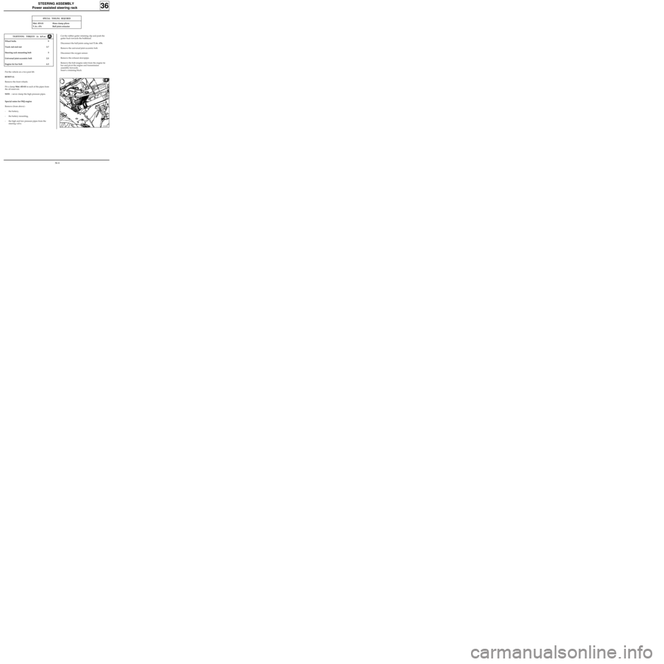
SPECIAL TOOLING REQUIRED
Mot. 453-01 Hose clamp pliers
T.Av. 476 Ball joint extractor
Wheel bolts 9
Track rod end nut 3.7
Steering rack mounting bolt 5
Universal joint eccentric bolt 2.5
Engine tie bar bolt 6.5
TIGHTENING TORQUES (in daN.m)
Put the vehicle on a two post lift.
REMOVAL
Remove the front wheels.
Fit a clamp Mot. 453-01 to each of the pipes from
the oil reservoir.
NOTE :never clamp the high pressure pipes.
Cut the rubber gaiter retaining clip and push the
gaiter back towards the bulkhead.
Disconnect the ball joints using tool T.Av. 476.
Remove the universal joint eccentric bolt.
Disconnect the oxygen sensor.
Remove the exhaust downpipe.
Remove the bolt (engine side) from the engine tie
bar and pivot the engine and transmission
assembly forwards.
Insert a retaining block.
Special notes for F8Q engine
Remove (from above) :
- the battery,
- the battery mounting,
- the high and low pressure pipes from the
steering valve.
13120S
36-4
Page 96 of 105
ELECTRONICALLY CONTROLLED HYDRAULIC SYSTEMS
BOSCH ABS
38
This vehicle is fitted with BOSCH ABS 5.3 of the four channel additional type; the conventional braking
equipment and the ABS equipment are separate.
SPECIAL NOTES
The system comprises four speed sensors. Each hydraulic braking channel is associated with a sensor at each
wheel. The front wheels are therefore regulated separately. The rear wheels however are regulated at the
same time and in the same way according to the select low principle (the first wheel which tends to lock
causes immediate regulation on the complete axle assembly). The compensator fulfils its normal function.
38-1
Page 100 of 105
WIRING DIAGRAM KEY
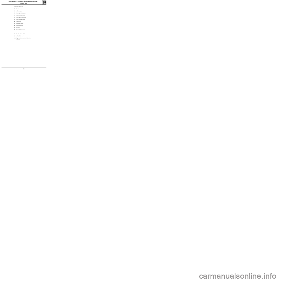
104Ignition switch
118 ABS computer
150Rear right wheel sensor
151Rear left wheel sensor
152Front right wheel sensor
153Front left wheel sensor
160Stop switch
225Diagnostic socket
247Instrument panel
260Fuse box
777Power feed fuse board
R2Dashboard / rear left
R36ABS / Dashboard
R101Right hand side member / Right hand
headlight
ELECTRONICALLY CONTROLLED HYDRAULIC SYSTEMS
BOSCH ABS
38
38-5
Page 101 of 105
ELECTRONICALLY CONTROLLED HYDRAULIC SYSTEMS
BOSCH ABS
38
PRN3813
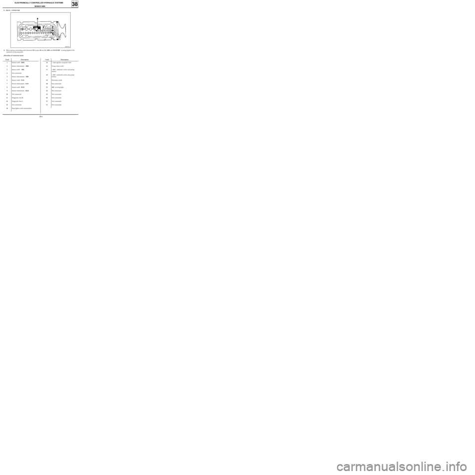
31 TRACK CONNECTOR
Track Description
1
2
3
4
5
6
7
8
9
10
11
12
13
14Sensor earth - RRH
Sensor information -
RRH
Sensor earth - FRH
Not connected
Sensor information -
FRH
Sensor earth - FLH
Sensor information - FLH
Sensor earth - RLH
Sensor information - RLH
Not connected
Diagnostic line K
Diagnostic line L
Not connected
Stop lights switch information
AMicro-spring connecting earth (terminal 19) to pins 20 and 21 (ABS and NIVOCODE warning lights) if the
connector is disconnected.
Allocation of connector tracks
Track Description
15
16
17
18
19
20
21
22
25
26
27
31+ after ignition computer feed
Pump motor earth
+ BAT (solenoid valves and pump
motor)
+ BAT (solenoid valves and pump
motor)
Electronic earth
Not connected
ABS warning light
Not connected
Not connected
Not connected
Not connected
Not connected
38-6
Page 105 of 105
ELECTRONICALLY CONTROLLED HYDRAULIC SYSTEMS
BOSCH ABS
38
2)Bleeding the hydraulic assembly.
IMPORTANT : the bleeding order must be observed, beginning with the rear right , then the rear left, front
left and then front right.
a)Bleed the rear right brake by bleeding the hydraulic assembly secondary circuit using the XR25:
- position the bleed container and the hose, open the brake bleed screw,
- pump the brake pedal (approximately ten times),
- start the bleed command on the
XR25,
- pump the brake pedal during the diagnostic bleed phase,
- at the end of the bleed cycle on the
XR25, continue to pump the brake pedal and close the brake
bleed screw.
b)Carry out the procedure described at a) for the rear left, front left and front right brakes.
c)Check the pedal travel and if it is incorrect, restart the bleeding procedure.
IMPORTANT : ensure there is sufficient brake fluid in the reservoir.
CHECKING THE WHEEL SPEED SENSORS
a)Check the resistance of the sensor connections (from the computer connector to the 2 track speed sensor
connector).
b)Visually inspect the teeth ( 26 teeth) on the target and if they are faulty, replace the target.
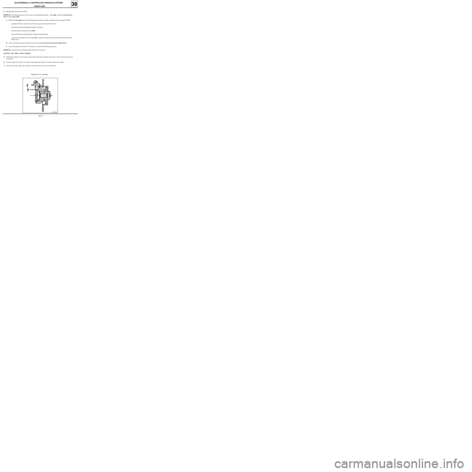
c)Check the air gap using a set of shims. Only the front sensors can be checked.
PRN3820
Front: 0.13 < Z < 1.96 mm
38-10