warning light RENAULT KANGOO 1997 KC / 1.G Chassis Workshop Manual
[x] Cancel search | Manufacturer: RENAULT, Model Year: 1997, Model line: KANGOO, Model: RENAULT KANGOO 1997 KC / 1.GPages: 105
Page 17 of 105

FRONT AXLE
Brake pads
31
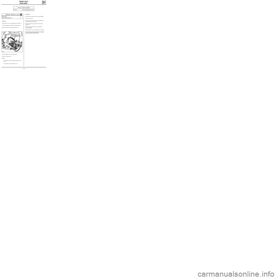
REMOVAL
Disconnect the wear warning light wire (if fitted).
Push the piston back, sliding the caliper by hand.
Remove the lower brake caliper guide bolt.
SPECIAL TOOLING REQUIRED
Fre. 823 Tool for pushing piston back
Wheel bolts 9
Brake caliper guide bolt 4
12994R
REFITTING
Push back the caliper piston using tool Fre. 823.
Fit new brake pads.
The brake pad with the wear warning light wire
(if fitted) is fitted to the inside.
Refit the caliper into position and fit the lower
guide bolt.
Tighten the guide bolt to the recommended
torque 4 daN.m.
Reconnect the wear warning light wire (if fitted).
Press the brake pedal several times to bring the
piston into contact with the pads.
TIGHTENING TORQUES (in daN.m)
Pivot the caliper around the upper bolt.
Remove the brake pads.
Check:
- the condition and mounting of the piston dust
cover,
- the condition of the guide dust cover.
31-4
Page 68 of 105

STEERING ASSEMBLY
Steering column
36
IMPORTANT : if these instructions are not
followed exactly the system may not operate
normally and could even be triggered incorrectly.
IMPORTANT
Before reconnecting the driver’s airbag cushion,
check to see if the system is operating correctly as
follows:
•check the airbag warning light on the
instrument panel is illuminated when the
ignition is on,
•connect a dummy ignition module to the
driver’s airbag connector and check that the
warning light extinguishes,
•switch the ignition off, connect the airbag
cushion in place of the dummy ignition module
and secure the cushion to the steering wheel,
•switch the ignition on. Check the warning light
illuminates for three seconds when the ignition
is switched on then extinguishes and remains
extinguished.
If the warning light does not operate as described
above, refer to the fault finding section and check
the system using the
XRBAG (Elé. 1288).
SPECIAL NOTES FOR VEHICLES FITTED WITH A
DRIVER’S AIRBAG
Ensure that the wheels are still straight.
Check that the rotary switch is still immobilised
before refitting.
If it is not, follow the method for centring
described in section 88 "driver’s airbag".
Renew the steering wheel bolt each time it is
removed ( pre-bonded bolt).
Observe the correct tightening torque ( 4.5
daN.m).
36-16
Page 97 of 105

ELECTRONICALLY CONTROLLED HYDRAULIC SYSTEMS
BOSCH ABS
38
PRN3818
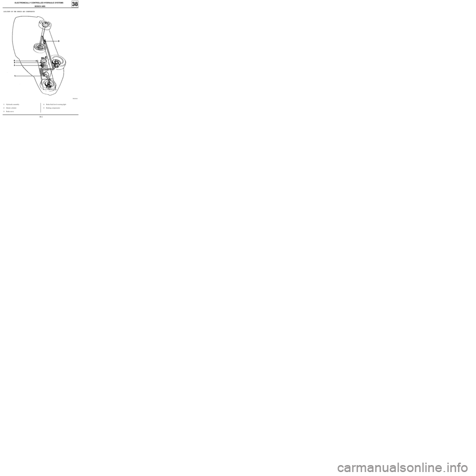
LOCATION OF THE BOSCH ABS COMPONENTS
1Hydraulic assembly
2Master cylinder
3Brake servo4Brake fluid level warning light
5Braking compensator
38-2
Page 101 of 105

ELECTRONICALLY CONTROLLED HYDRAULIC SYSTEMS
BOSCH ABS
38
PRN3813
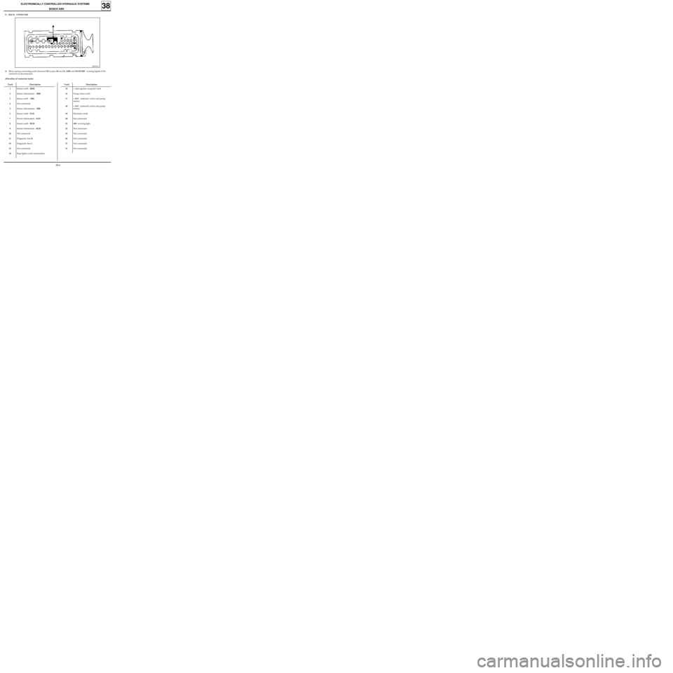
31 TRACK CONNECTOR
Track Description
1
2
3
4
5
6
7
8
9
10
11
12
13
14Sensor earth - RRH
Sensor information -
RRH
Sensor earth - FRH
Not connected
Sensor information -
FRH
Sensor earth - FLH
Sensor information - FLH
Sensor earth - RLH
Sensor information - RLH
Not connected
Diagnostic line K
Diagnostic line L
Not connected
Stop lights switch information
AMicro-spring connecting earth (terminal 19) to pins 20 and 21 (ABS and NIVOCODE warning lights) if the
connector is disconnected.
Allocation of connector tracks
Track Description
15
16
17
18
19
20
21
22
25
26
27
31+ after ignition computer feed
Pump motor earth
+ BAT (solenoid valves and pump
motor)
+ BAT (solenoid valves and pump
motor)
Electronic earth
Not connected
ABS warning light
Not connected
Not connected
Not connected
Not connected
Not connected
38-6