instrument panel RENAULT KANGOO 1997 KC / 1.G Electrical Equipment Owner's Manual
[x] Cancel search | Manufacturer: RENAULT, Model Year: 1997, Model line: KANGOO, Model: RENAULT KANGOO 1997 KC / 1.GPages: 83
Page 40 of 83
INSTRUMENT PANEL
Coolant temperature sensor
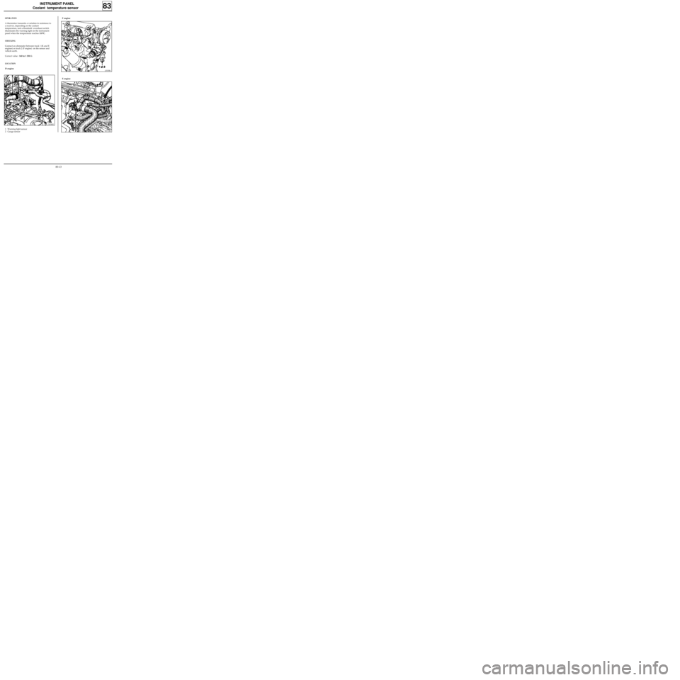
F engine
83
12535R1
OPERATION
A thermistor transmits a variation in resistance to
a receiver, depending on the coolant
temperature, and a threshold overshoot switch
illuminates the warning light on the instrument
panel when the temperature reaches 118°C.
CHECKING
Connect an ohmmeter between track 1 (K and E
engines) or track 2 (F engine) on the sensor and
vehicle earth.
Correct value : 160 to 1 250 Ω.
LOCATION
D engine
E engine
98711R4
11634R3
1 Warning light sensor
2 Gauge sensor
83-13
Page 43 of 83
CONTROLS - SIGNALS
Stalk mounting
REMOVAL - REFITTING
Disconnect the battery and set the wheels
straight.
Remove the steering wheel and the two half cow-
lings (for vehicles with an airbag, refer to the re-
moval of the rotary switch on the following page
or section 88 for special notes on removing the
steering wheel).
Special notes for vehicles with an airbag
Before removing the assembly, the position of the
rotary switch under the steering wheel must be
noted:
- by ensuring that the wheels are straight on re-
moval so that the strip may be positioned in the
centre,
- by immobilising the rotary switch rotor using
adhesive tape.
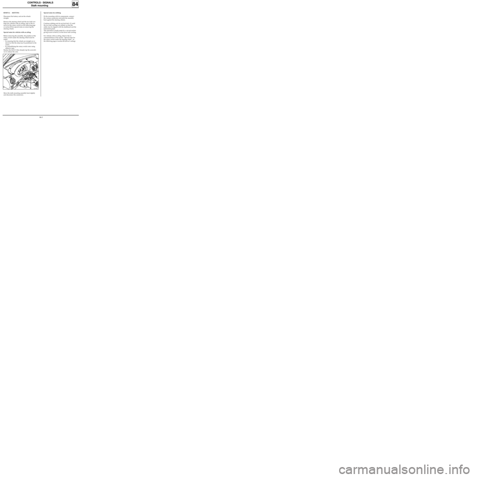
Slacken the bolt (C) then sharply tap the screwdri-
ver to release the cone.
84
Special notes for refitting
Fit the mounting with its components, connect
the various connectors and push the assembly
back against the steering column.
Continue refitting and do not lock bolt (C) until
the two half cowlings are refitted, so that the
stalks may be aligned with the dashboard and the
instrument panel.
This operation is made easier by a cut-out section
giving access to bolt (C) in the lower half cowling.
For vehicles with an airbag, observe the re-
commendations in the section " Special notes for
the rotary switch under the steering wheel" on
the following page or section 88 (driver’s airbag).
12970R2
Move the stalk mounting assembly back slightly
and disconnect the connectors.
84-3
Page 45 of 83
CONTROLS - SIGNALS
Rotary switch under steering wheel
Special notes for refitting
Ensure the wheels are still straight.
Ensure the rotary switch under the steering wheel
is still immobilised before refitting.
If there is any doubt follow the method for cen-
tring described in section 88 "driver’s airbag".
Renew the steering wheel bolt each time it is re-
moved (pre-bonded bolt).
Observe the correct tightening torque (4.5
daN.m).
84
IMPORTANT
Before reconnecting the driver’s airbag cushion,
check to see if the system is operating correctly as
follows:
•check the airbag warning light on the
instrument panel is illuminated when the
ignition is on,
•connect a dummy ignition module to the
driver’s airbag connector and check that the
warning light extinguishes,
•switch the ignition off, connect the airbag
cushion in place of the dummy ignition module
and secure the cushion to the steering wheel,
•switch the ignition on. Check the warning light
illuminates for three seconds when the ignition
is switched on then extinguishes and remains
extinguished.
If the warning light does not operate exactly as
described above, refer to the fault finding section
and test the system using the XRBAG (Elé. 1288)
(see section 88).
IMPORTANT: if these instructions are not obser-
ved, the systems may not operate normally and
may be incorrectly triggered.
84-5
Page 60 of 83

WIRING
Remote control for door locking
88
Ignition off:
1.Press and hold the central door locking button
for a few seconds until the doors lock and un-
lock.
From this moment, the operator has 10 se-
conds to carry out the next operation.
NOTE: The 10 seconds are shown by the illu-
mination of the red immobiliser warning light
(if fitted) and bargraph 17 LH on the XR25
(code
D56, fiche n° 56).
2.Press the remote control twice (the doors lock
and unlock and the red warning light extin-
guishes, if fitted).
NOTE : If both remote controls (if fitted) are
desynchronised, two resynchronisation proce-
dures will have to be carried out (one for each
remote control).
IMPORTANT: To ensure that the infrared code
is correctly transmitted it is essential to direct
the transmitter correctly towards the receiver.
If the procedure fails it will be necessary to
restart from the beginning (infrared remote
control only).
3.The procedure is complete - check that the
doors lock correctly.
Removal - Refitting
The dashboard must be partially removed to re-
move the decoder unit.
Remove:
- the steering wheel with the wheels straight,
- the half cowlings under the steering wheel,
- the knee protector under the steering column,
- the lights and wiper controls,
- the instrument panel surround,
- the instrument panel,
- the ashtray, its mounting and the two dash-
board mounting bolts on the heating unit,
- the trim at the bottom of the dashboard on the
driver’s side,
- the two speaker grilles on the dashboard,
- the dashboard mountings.
THE DECODER UNIT
The decoder unit is located in the left hand side of
the dashboard (A).
12967R
88-5
Page 67 of 83

WIRING
Airbags and seat belt pretensioners
88
PRD99498
This bornier is connected instead of the computer,
fitted with a single 30-track connector.
It enables all the ignition lines to be checked by
means of the XRBAG, the supply voltage of the
computer to be measured, and the airbag war-
ning light on the instrument panel to be illumina-
ted.
Terminals also enable the continuity checks to be
carried out on the diagnostic lines, the warning
light lines and the feed to the computer (see sec-
tion on fault finding).
XRBAG TEST UNIT (Elé. 1288)
96833G
This unit is a tool specifically designed for testing
and fault finding on airbag devices and seat belt
pretensioners.
It enables electrical measurements to be carried
out on the different lines in the systems.
(See "fault finding" section).
IMPORTANT: It is not permitted to carry out mea-
surements on these systems with an ohmmeter or
any other electrical measuring instrument: there
is a risk of triggering due to the operating current
of the instrument.
XRBAG 30-TRACK ADAPTER
88-12
Page 69 of 83

WIRING
Airbags and seat belt pretensioners
88
When refitting the computer, it MUST be moun-
ted on the vehicle before its connectors are re-
connected.
The arrow on the computer must point towards
the front of the vehicle.
Vehicle fitted with airbag(s)
Lock the computer using the XR25 and command
G80* (ISO selector on S8 code D49).
When this function is active, all the trigger lines
are inhibited, the airbag warning light on the ins-
trument panel and bargraph 14 LH on the XR25 il-
luminate (new computers are supplied in this
condition).
When refitting the computer:
- Mount it on the vehicle (the arrow on the
computer must point towards the front of the
vehicle).
- Connect the 30 track computer connector and
carry out a check using the XR25.
If everything is correct, unlock the computer using
command G81*.COMPUTER
Several types of unit may be found:
- one computer for pretensioners only.
- one computer for pretensioners and airbag(s).
Depending on function, these computers have:
- an electromagnetic safety sensor,
- a decelerometer for the airbags
- an ignition circuit for the different pyrote-
chnic systems,
- a power reserve,
- a diagnostic and detected fault storage circuit
(except pretensioner only),
- a control circuit for the warning light on the
instrument panel (except pretensioner only),
- a K - L communication interface via the dia-
gnostic socket (except pretensioner only).
IMPORTANT
Before removing the computer:
Vehicle with pretensioners only (no air-bag) :
- Switch off the ignition.
- Remove the feed fuse (see fuse allocation) and
wait for 5 minutes for the reserve capacity to
discharge.
- Disconnect the computer connector to avoid
any risk of triggering.
- Ensure no-one is in the passenger compartment
during the complete operation on the compu-
ter.
88-14
Page 75 of 83
WIRING
Airbags and seat belt pretensioners
88
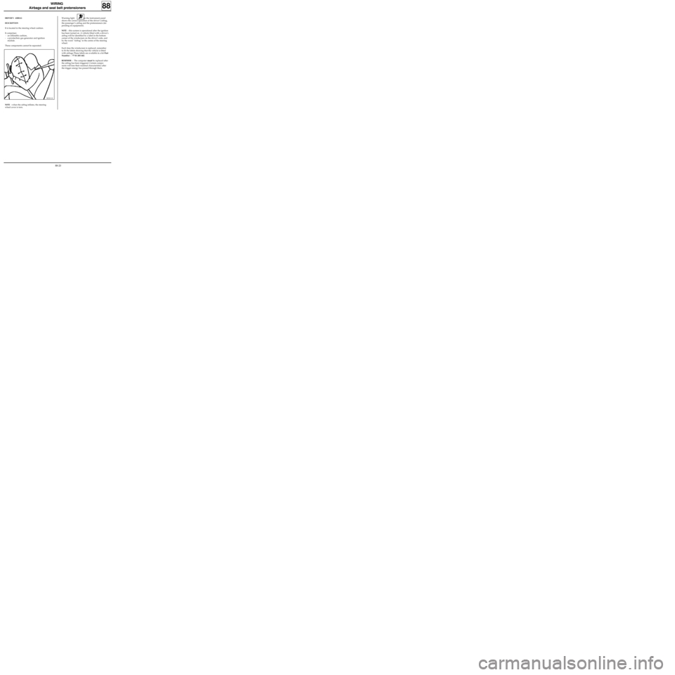
DRIVER’S AIRBAG
DESCRIPTION
It is located in the steering wheel cushion.
It comprises:
- an inflatable cushion,
- a pyrotechnic gas generator and ignition
module.
These components cannot be separated.
96310-1S
NOTE : when the airbag inflates, the steering
wheel cover is torn.Warning light on the instrument panel
shows the correct operation of the driver’s airbag,
the passenger’s airbag and the pretensioners (de-
pending on equipment).
NOTE : this system is operational after the ignition
has been turned on. A vehicle fitted with a driver’s
airbag will be identified by a label in the bottom
corner of the windscreen on the driver’s side, and
by the word "Airbag" in the centre of the steering
wheel.
Each time the windscreen is replaced, remember
to fit the labels showing that the vehicle is fitted
with airbags.These labels are available in a kit Part
Number : 77 01 205 442.
REMINDER : The computer must be replaced after
the airbag has been triggered. Certain compo-
nents will lose their nominal characteristics after
the trigger energy has passed through them.
88-20
Page 79 of 83
WIRING
Airbags and seat belt pretensioners
88
PASSENGER AIRBAG MODULE
DESCRIPTION:
It is located in the dashboard, opposite the front
seat passenger.
It comprises:
- an inflatable cushion,
- two pyrotechnic gas generators and ignition
modules.
LOCATION
The components of the airbag module cannot be
separated.
98124S
NOTE : When it is triggered, the airbag opens the
plastic cover of the passenger airbag module.
Warning light on the instrument panel
shows the correct operation of the airbags and
the pretensioners.
NOTE : this system is operational after the ignition
has been turned on. A vehicle fitted with a pas-
senger’s airbag will be identified by a label in the
bottom corner of the windscreen on the passen-
ger’s side, and by the word "Airbag" on the dash-
board on the same side. Two additional labels on
the front window and the side of the dashboard
indicate that a child seat cannot be fitted to the
front seat. The passenger must not set his feet on
the dashboard or stick or pin objects to the dash-
board (refer to the Driver’s Handbook).
Each time the windscreen (or passenger door win-
dow) is replaced, remember to fit the labels sho-
wing that the vehicle is fitted with airbags.These
labels are available in a kit Part Number : 77 01
205 442.
REMINDER : The computer must be replaced after
the airbag has been triggered. Certain compo-
nents will lose their nominal characteristics after
the trigger energy has passed through them.
13060S
88-24