radio controls RENAULT KANGOO 1997 KC / 1.G Electrical Equipment Workshop Manual
[x] Cancel search | Manufacturer: RENAULT, Model Year: 1997, Model line: KANGOO, Model: RENAULT KANGOO 1997 KC / 1.GPages: 83
Page 10 of 83

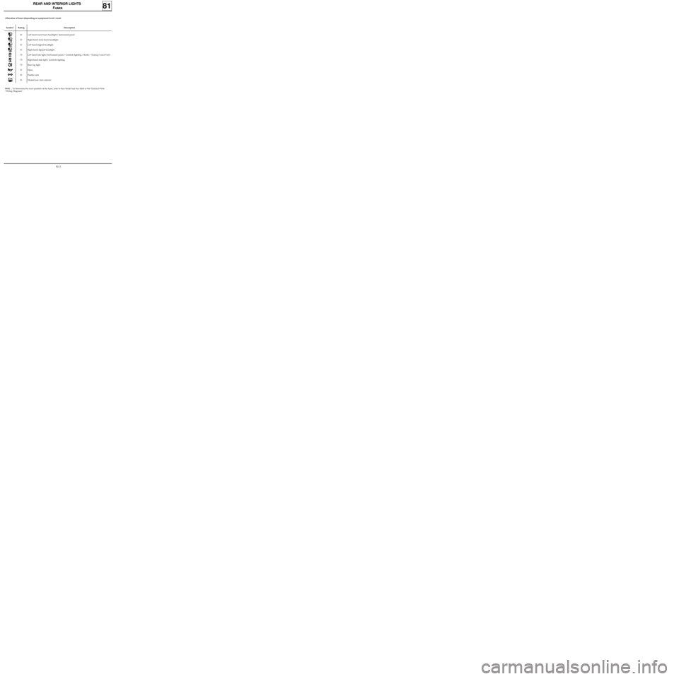
Symbol Rating Description
10
10
10
10
7.5
7.5
7.5
15
10
10Left hand main beam headlight/ Instrument panel
Right hand main beam headlight
Left hand dipped headlight
Right hand dipped headlight
Left hand side light/
Instrument panel / Controls lighting / Radio / Heating Control Panel
Right hand side light/ Controls lighting
Rear fog light
Horn
Flasher unit
Heated rear view mirrors
REAR AND INTERIOR LIGHTS
Fuses
81
NOTE : To determine the exact position of the fuses, refer to the vehicle fuse box label or the Technical Note
"Wiring Diagrams".
Allocation of fuses (depending on equipment level). (cont)
81-3
Page 46 of 83

CONTROLS - SIGNALS
Ignition switch
REMOVAL - REFITTING
Disconnect the battery.
Set the wheels straight.
Remove:
- the half cowlings,
- the radio or glovebox (depending on equip-
ment),
- the immobiliser antenna ring or plastic sur-
round from the ignition switch (depending on
equipment).
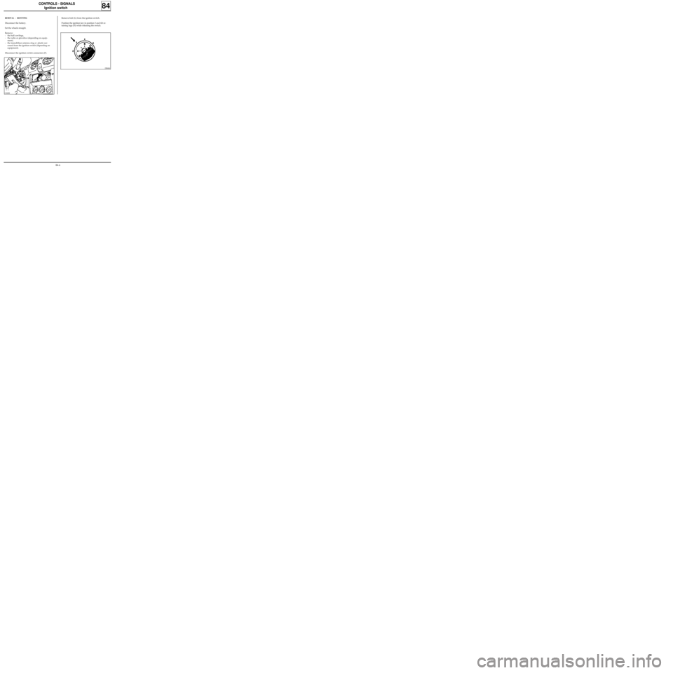
Disconnect the ignition switch connectors (F).
84
Remove bolt (G) from the ignition switch.
Position the ignition key in position 3 and tilt re-
taining lugs (H) while releasing the switch.
DI8404
13068R
84-6
Page 58 of 83

WIRING
Remote control for door locking
88
.GENERAL
These vehicles are equipped with an infrared or
radio frequency remote control with rolling code,
which prevents the code from being copied.
When a transmitter is replaced it will therefore be
necessary to resynchronise it so that the transmit-
ters are returned to phase with the decoder unit.
This remote control is only used for locking and
unlocking the opening elements (it has no effect
on the immobiliser).
IMPORTANT: this system cannot operate with
three remote controls (the decoder unit can only
manage two different rolling codes).
THE TRANSMITTER (PLIP)
Replacing or adding a remote control with immo-
biliser function without replacing the decoder
unit.
Order a spare key head using the number in the
head of one of the old keys or the label normally
attached to the keys when the vehicle is delivered
(eight alphanumeric characters).
If a key is being added or has been lost, remember
to order the insert with the key number.
Carry out the special resynchronisation procedure
using the XR25.
This procedure resets the remote control into se-
quence with the decoder unit (rolling code) and
should only be used if the decoder unit is not
being replaced (with immobiliser only).
1.Ignition off, connect the XR25 (ISO selector on
S8, code D56).
For vehicles fitted with an infra-red remote
control, enter command mode G04* (forced
protection mode) then switch the ignition on
again and enter the vehicle’s security code
(see procedure in section 82).
For vehicles fitted with a radio frequency re-
mote control, go to point 2.
2.Switch the ignition off and enter command
mode G32*.
From this moment, the operator has 10 se-
conds to carry out the next operation.
NOTE: The 10 seconds are shown by the illu-
mination of the red immobiliser warning light
and bargraph 17 LH on the XR25
(code D56,
fiche n° 56).
3.Press the remote control twice (the doors lock
and unlock and the red warning light extin-
guishes).
NOTE :
- When replacing a key head, resynchronisa-
tion of the second remote control (if fitted)
is not always necessary.
Check that the second control operates,
otherwise resynchronise it.
- If both remote controls (if fitted) are desyn-
chronised, two resynchronisation proce-
dures will have to be carried out (one for
each remote control).
IMPORTANT: To ensure that the infrared code
is correctly transmitted it is essential to direct
the transmitter correctly towards the receiver.
If the procedure fails it will be necessary to
restart from the beginning (infrared remote
control only).
4.The procedure is complete - check that the
doors lock correctly.
88-3