heater RENAULT KANGOO 1997 KC / 1.G Engine And Peripherals Workshop Manual
[x] Cancel search | Manufacturer: RENAULT, Model Year: 1997, Model line: KANGOO, Model: RENAULT KANGOO 1997 KC / 1.GPages: 208
Page 10 of 208
ENGINE AND ENGINE PERIPHERALS
Engine - Gearbox
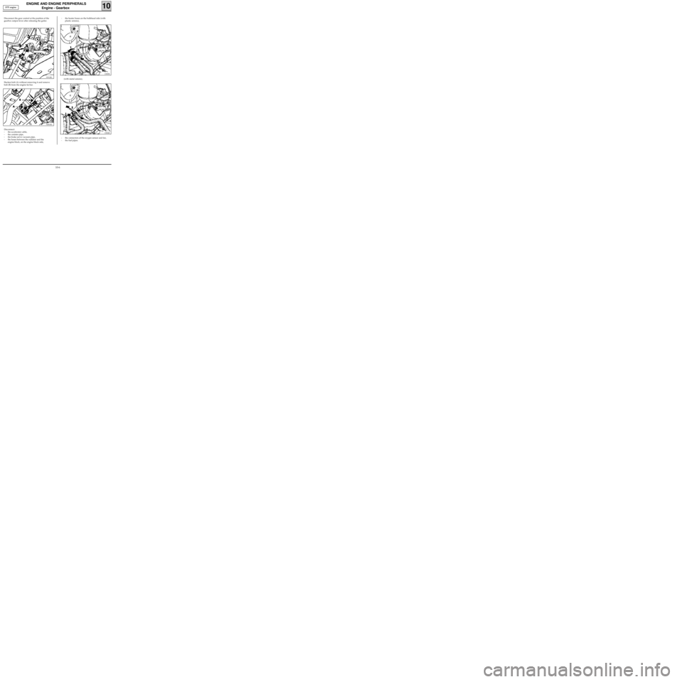
- the heater hoses on the bulkhead side (with
plastic unions),
10
Disconnect the gear control at the position of the
gearbox output lever after releasing the gaiter.
93912R1
Slacken bolt (A) without removing it and remove
bolt (B) from the engine tie-bar.
92661R1
Disconnect:
- the accelerator cable,
- the canister pipe,
- the brake servo vacuum pipe,
- the hoses between the radiator and the
engine block, on the engine block side,
13085R
(with metal unions),
13084R
- the connectors of the oxygen sensor and fan,
- the fuel pipes. D7F engine
10-6
Page 14 of 208
ENGINE AND ENGINE PERIPHERALS
Engine and transmission assembly
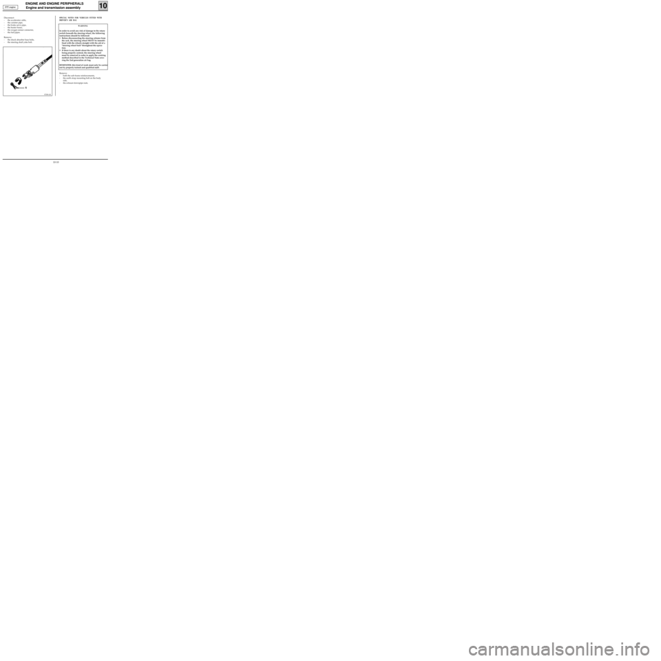
Disconnect:
- the accelerator cable,
- the canister pipe,
- the brake servo pipe,
- the heater hoses,
- the oxygen sensor connector,
- the fuel pipes.
Remove:
- the shock absorber base bolts,
- the steering shaft yoke bolt.
10
97390-1R
SPECIAL NOTES FOR VEHICLES FITTED WITH
DRIVER’S AIR BAG
WARNING
In order to avoid any risk of damage to the rotary
switch beneath the steering wheel, the following
instructions should be followed:
• Before disconnecting the steering column from
the rack, the steering wheel MUST be immobi-
lised with the wheels straight with the aid of a
"steering wheel lock" throughout the opera-
tion.
• If there is any doubt about the rotary switch
being properly centred, the steering wheel
must be removed in order to apply the centring
method described in the Technical Note cove-
ring the 2nd generation air bag.
REMINDER: this kind of work must only be carried
out by properly trained and qualified staff.
Remove:
- both the sub-frame reinforcements,
- the earth strap mounting bolt on the body
side,
- the exhaust downpipe nuts. D7F engine
10-10
Page 19 of 208
ENGINE AND ENGINE PERIPHERALS
Engine and transmission assembly
10
13085R
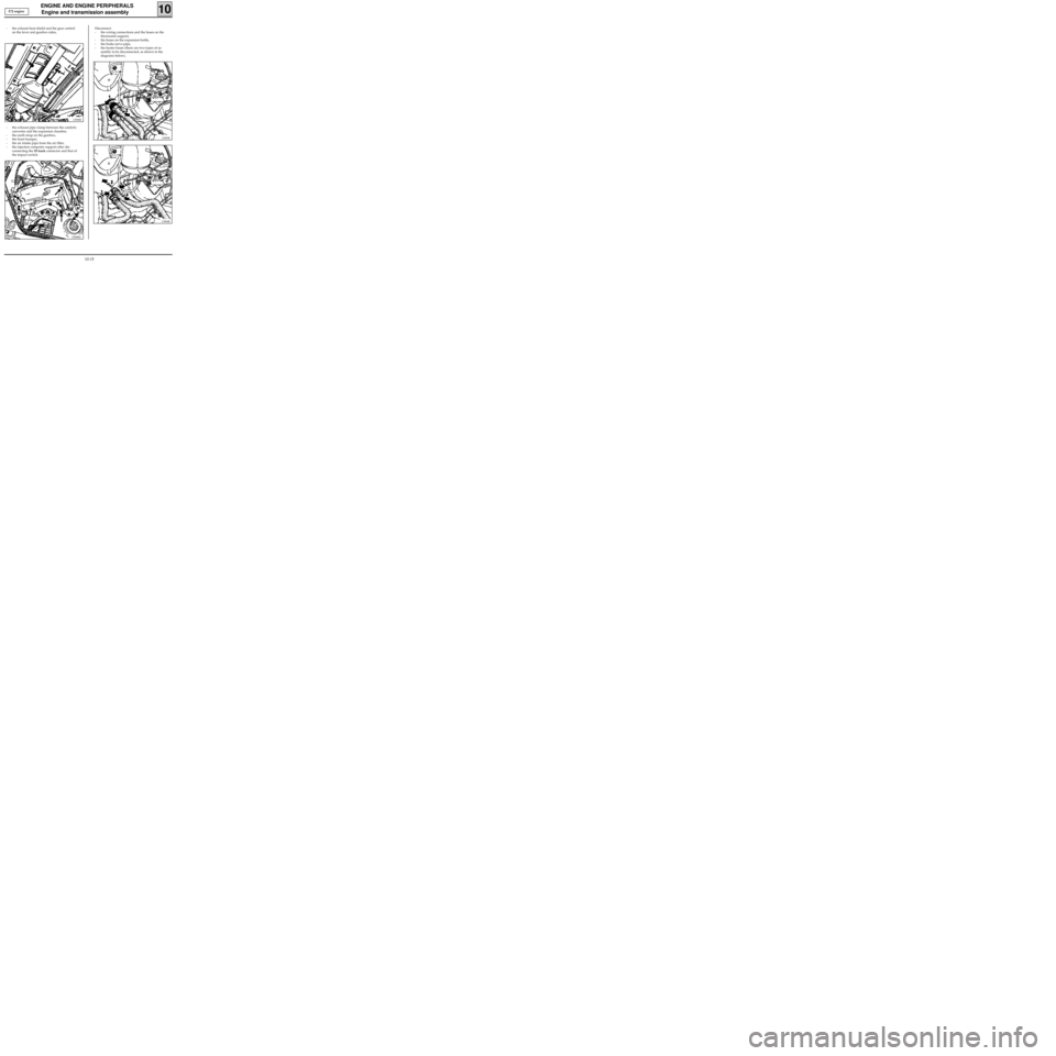
- the exhaust heat shield and the gear control
on the lever and gearbox sides,
12988R
- the exhaust pipe clamp between the catalytic
converter and the expansion chamber,
- the earth strap on the gearbox,
- the front bumper,
- the air intake pipe from the air filter,
- the injection computer support after dis-
connecting the 55 track connector and that of
the impact switch.
13088R2
Disconnect:
- the wiring connections and the hoses on the
thermostat support,
- the hoses on the expansion bottle,
- the brake servo pipe,
- the heater hoses (there are two types of as-
sembly to be disconnected, as shown in the
diagrams below),
13084R
E7J engine
10-15
Page 25 of 208
ENGINE AND ENGINE PERIPHERALS
Engine and transmission assembly
10
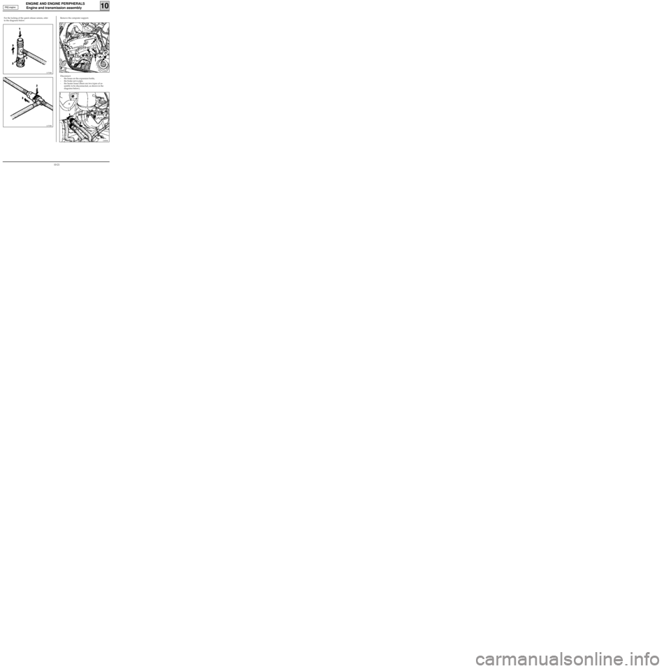
Remove the computer support.
13088R1
Disconnect:
- the hoses on the expansion bottle,
- the brake servo pipe,
- the heater hoses (there are two types of as-
sembly to be disconnected, as shown in the
diagrams below),
13085R
F8Q engine
11734R
For the locking of the quick release unions, refer
to the diagrams below:
11733R
10-21
Page 47 of 208
TOP AND FRONT OF ENGINE
Cylinder head gasket
11
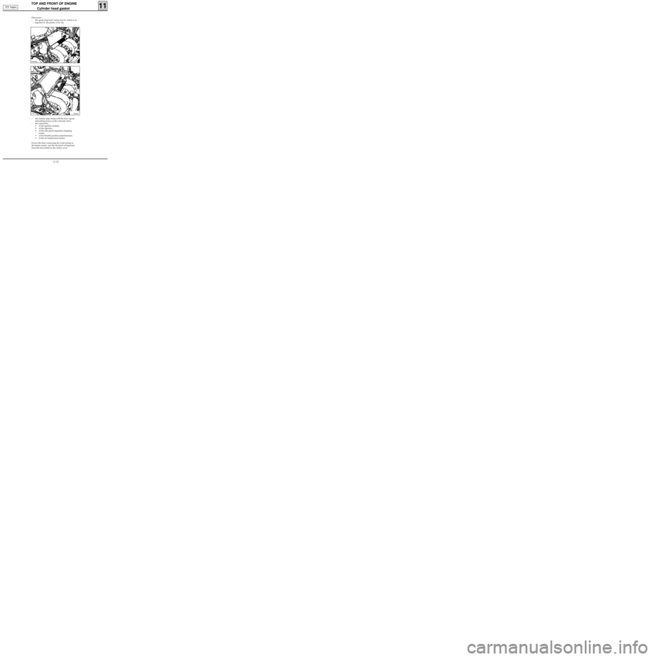
- the canister pipe along with the fuel vapour
rebreathing hoses on the solenoid valve,
- the connectors :
• of the ignition module,
• of the injectors,
• of the idle speed regulation stepping
motor,
• of the throttle position potentiometer,
• of the air temperature sensor.
Extract the hose connecting the water pump to
the heater matrix, and the electrical wiring loom
from the heat shield on the rocker cover.
99940R
Disconnect :
- the spark plug leads using tool (3) which is in-
tegrated to the plastic cover (4),
99894R1
D7F Engine
11-12
Page 59 of 208
TOP AND FRONT OF ENGINE
Cylinder head gasket
11
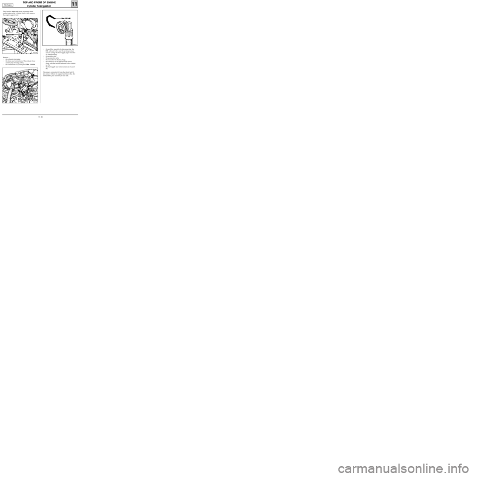
Remove :
- the exhaust downpipe,
- the hoses and connectors of the cylinder head
coolant pipe housing outlet,
- the connection at (1) using tool Mot. 1311-06,
13097R
99461R
- the air filter assembly by disconnecting the
EGR solenoid valve and the air temperature
sensor (unclip the fuel supply pipes from the
air filter housing),
- the air inlet pipe
- the accelerator cable
- the feeds for the heater plugs ,
- the connector of the injector with sensor,
along with the fast idle solenoid valve connec-
tor (5),
- the fuel supply and return unions at (A) and
(B).
Disconnect connector (6) from the diesel fuel fil-
ter, remove it from its support and move the die-
sel fuel filter pipe assembly to one side. Place bracket Mot. 1159 at the mounting of the
coolant pipe on the cylinder block, then remove
the engine support tool.
99310R
F8Q Engine
11-24
Page 93 of 208
DIESEL EQUIPMENT
General
13
The use of electronic injection in Diesel engines has allowed the operational power of these engines to be
optimised, thus reducing the emission rate of pollutant gases.
The system consists of a computer, which receives information from:
- the coolant temperature sensor,
- the air temperature sensor,
- the engine speed sensor,
- the vehicle speed sensor,
- the load potentiometer,
- the injection start sensor, which forms part of the injector of cylinder n° 3 (injector with sensor).
It controls :
- the injection pump :
• the altimetric corrector (F8Q 630) via a relay
• the advance solenoid valve.
- the cold engine starting system (heater plugs and pre-postheating unit),
- the exhaust gas recycling system (EGR),
- the diesel injection fault warning light,
- the preheating warning light,
- the solenoid valve controlling the fast idle speed LDA,
- the relay controlling the power assisted steering electric pump assembly (for vehicles with air conditio-
ning), the pump assembly is supplied once the engine speed exceeds 650 rpm.
It carries out a self diagnosis procedure which may be visualised through the
XR25.
SPECIAL FEATURES
On the injection pump it is possible to replace:
- the load potentiometer,
- the advance solenoid valve,
- the altimetric corrector,
- the electrical solenoid.
13-13
Page 118 of 208
DIESEL EQUIPMENT
Defect modes
13
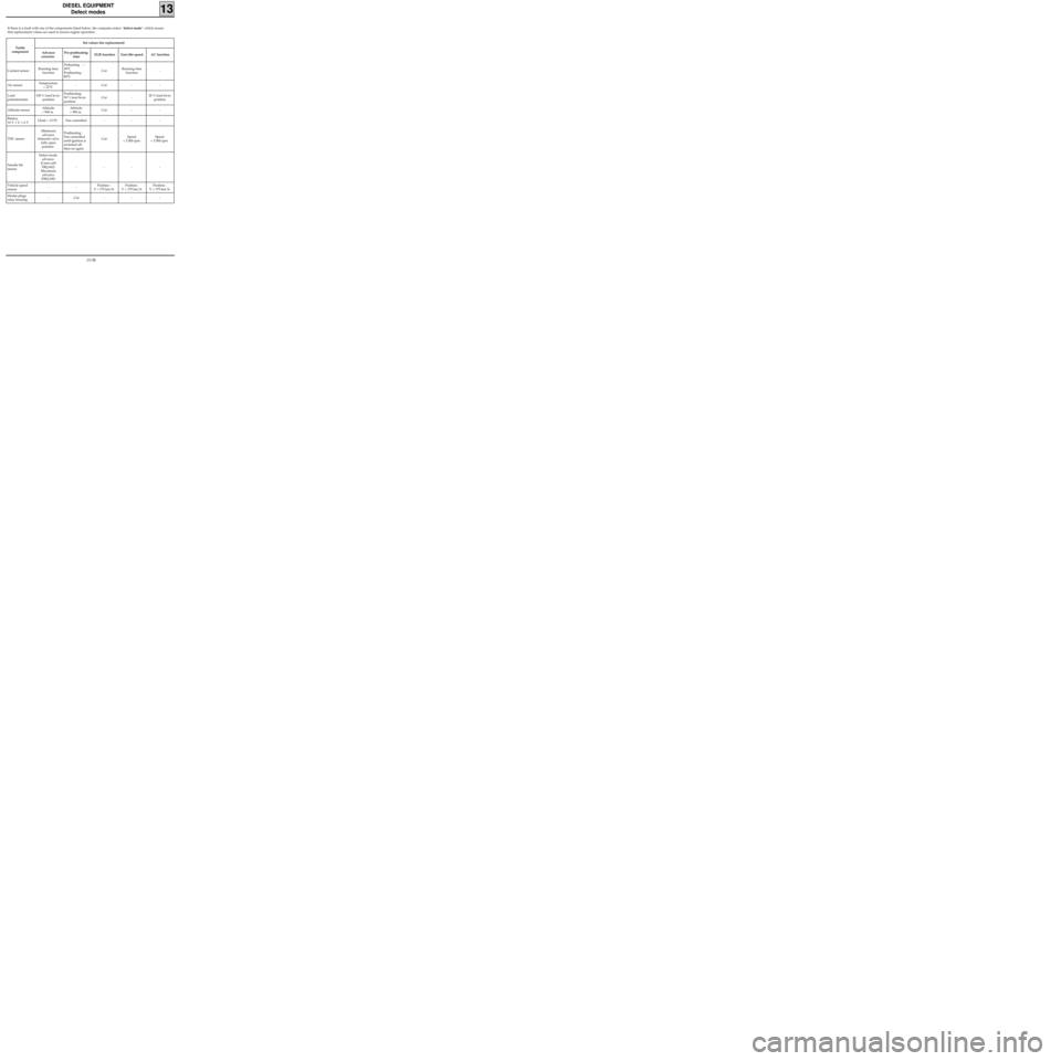
If there is a fault with one of the components listed below, the computer enters "defect mode", which means
that replacement values are used to ensure engine operation.
Faulty
componentSet values (for replacement)
Advance
corrector Pre-postheating
timeEGR function Fast idle speed AC function
Coolant sensorRunning time
functionPreheating : -
30°C
Postheating :
80°CCutRunning time
function-
Air sensorTemperature
= 22°C- Cut - -
Load
potentiometer100 % load lever
positionPostheating:
30 % load lever
position Cut - 20 % load lever
position
Altitude sensorAltitude
= 900 mAltitude
= 900 mCut - -
Battery
16 V < U < 6 VUbatt = 13.5V Not controlled - - -
TDC sensorMinimum
advance
Solenoid valve
fully open
position Postheating :
Not controlled
until ignition is
switched off
then on againCutSpeed
= 2 000 rpmSpeed
= 2 000 rpm
Needle lift
sensorDefect mode
advance
(Carto soft
F8Q 662)
Maximum
advance
(F8Q 630)----
Vehicle speed
sensor--Position :
V = 175 km/hPosition :
V = 175 km/hPosition :
V = 175 km/h
Heater plugs
relay housing- Cut - - -
13-38
Page 176 of 208
COOLING
Filling and bleeding
19
There is no heater matrix water control valve.
Water flow is continuous in the heater matrix,
which contributes to the cooling of the engine.
FILLING
Check the tightening of the drain plug(s).
Open the two bleed screws.
Fill the circuit through the opening in the expan-
sion bottle.
Tighten the bleed screws as soon as the liquid
flows in a continuous jet.
Start the engine (2 500 rpm).
Adjust the level by overflow for a period of about
4 minutes .
Close the bottle.
BLEEDING
Allow the engine to run for about 10 minutes at
2 500 rpm, until the fan(s) operate (time necessary
for automatic degassing).
Check the liquid level is at the "Maximum" mar-
ker.
DO NOT OPEN THE BLEED SCREWS WHILST THE
ENGINE IS TURNING.
RE-TIGHTEN THE EXPANSION BOTTLE CAP WHILST
THE ENGINE IS WARM.
19-2
Page 178 of 208
COOLING
Diagram
19
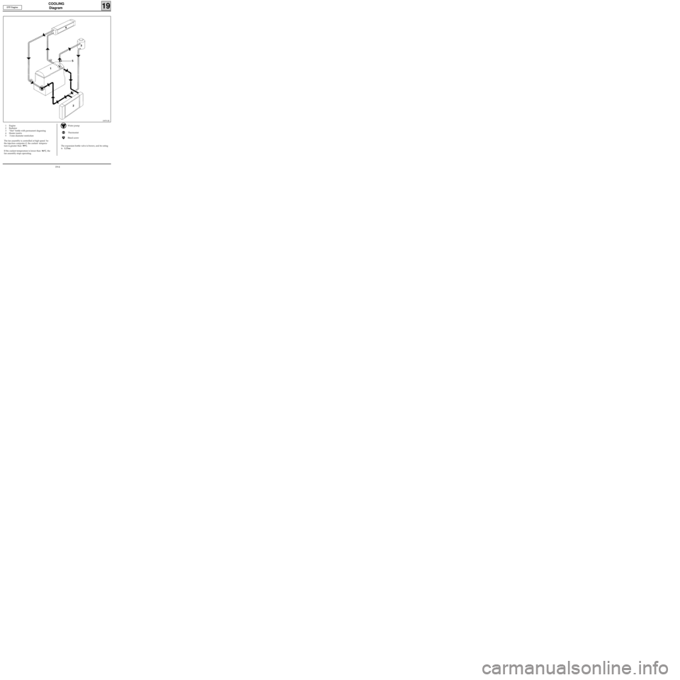
1 Engine
2 Radiator
3 ”Hot” bottle with permanent degassing
4 Heater matrix
5 3 mm diameter restriction
The fan assembly is controlled at high speed by
the injection computer if the coolant tempera-
ture is greater than 99°C.
If the coolant temperature is lower than 96°C, the
fan assembly stops operating.Water pump
Thermostat
Bleed screw
The expansion bottle valve is brown, and its rating
is 1.2 bar.
10070-2R
D7F Engine
19-4