engine oil RENAULT KANGOO 1997 KC / 1.G Engine And Peripherals Owner's Manual
[x] Cancel search | Manufacturer: RENAULT, Model Year: 1997, Model line: KANGOO, Model: RENAULT KANGOO 1997 KC / 1.GPages: 208
Page 70 of 208
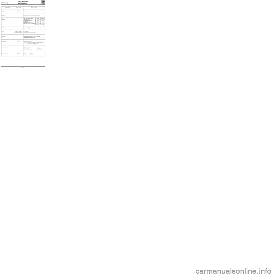
FUEL MIXTURE
Specifications
12
DESCRIPTIONMAKE/TYPESPECIAL NOTES
ComputerSIEMENS
FENIX 555tracks
Injection - Multipoint with semi-sequential regulation
Ignition
-Static with 2 dual output
monobloc coils
Power module integral
in computer
One pinking sensor
tightening torque : 2.5 daN.m
TDC sensor - Resistance 220 Ω
Plugs
EYQUEM : RFC52LS
CHAMPION
: RC10PYC
Gap: 0.9 mm
Tightening torque: 2.5 to 3 daN.m
Fuel filter - Mounted under vehicle in front of fuel tank
Replaced during major service
Fuel pump
WALBROSubmerged in fuel tank
Flow: at least 80 litres/hour at a regulated pressure
of 3 bars and a voltage of 12 V
Pressure regulator
-
Regulated pressure
Zero vacuum :3 ± 0.2 bars
Vacuum of 500 mbars :2.5 ± 0.2 bars
Solenoid injectors
SIEMENSVoltage:12 Volts
Resistance :14.5 ± 1 Ω
Tracks Resistance
1 - 2 0.5 Ω
1 - 3
2 -31 Ω
HT - HT10 KΩ
E7J engine
12-5
Page 133 of 208

ANTIPOLLUTION
Oil vapour rebreathing
14
CIRCUIT DIAGRAM
1 Cylinder head cover
2 Inlet manifold
3 Oil vapour rebreathing pipe connected upstream from the throttle body (the circuit is used
for medium and high loads)
4 Oil vapour rebreathing pipe connected downstream from the throttle body
5 Air pipe
6 Throttle body
99932R
D7F Engine
14-7
Page 134 of 208
ANTIPOLLUTION
Oil vapour rebreathing
14
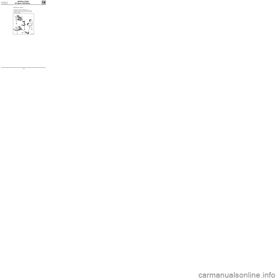
CHECKING THE CIRCUIT
To ensure the correct operation of the
antipollution system, it is important to keep the
oil vapour rebreathing system clean and in good
working condition.
PRC14.2
D7F Engine
14-8
Page 135 of 208
ANTIPOLLUTION
Oil vapour rebreathing
14E7J Engine
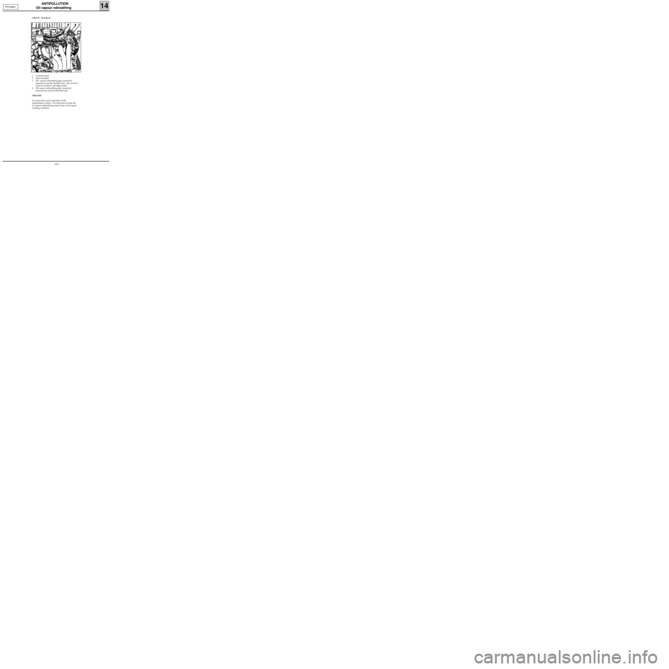
CIRCUIT DIAGRAM
1 Cylinder head
2 Inlet manifold
3 Oil vapour rebreathing pipe connected
upstream from the throttle body (the circuit is
used for medium and high loads)
4 Oil vapour rebreathing pipe connected
downstream from the throttle body
CHECKING
To ensure the correct operation of the
antipollution system, it is important to keep the
oil vapour rebreathing system clean and in good
working condition.
13335R
14-9
Page 136 of 208
ANTIPOLLUTION
Oil vapour rebreathing
14
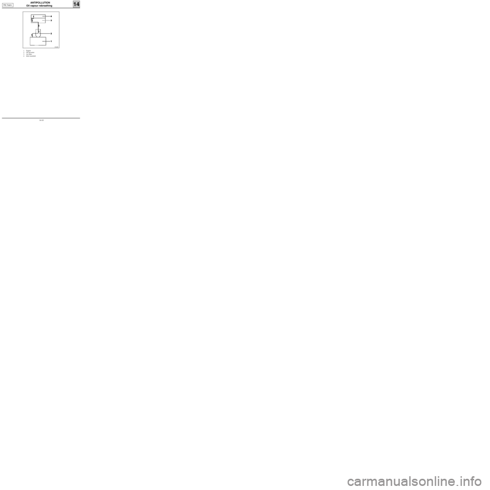
1 Engine
2 Oil decanter
3 Air filter
4 Inlet manifold
13042R
F8Q Engine
14-10
Page 151 of 208
IGNITION
Semi-static ignition
17
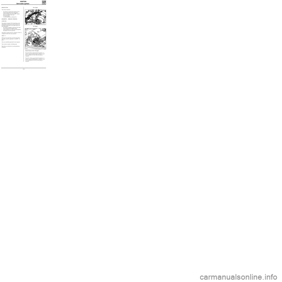
PRESENTATION
The system comprises:
- the injection computer (the ignition power
stage is integrated into the computer),
- two dual output coils, (for the
D7F engine,
these are moulded into one),
- four spark plugs,
- an anti-interference condenser (4).
DESCRIPTION - OPERATING PRINCIPLE
COMPUTER
The injection computer (120), depending on the
information received from various sensors, but
principally depending on the engine speed and
load, determines:
- the number of degrees of advance to be used
and consequently the ignition point,
- which cylinders are at TDC and consequently
the ignition coil to be operated.
The spark is created at the two cylinders at TDC by
cutting the earth to the coil concerned.
COILS (1)
There are two coils. They are of the dual output
type (they cannot be separated in the
D7F en-
gine ).
They are controlled separately by the computer.
They create two sparks simultaneously.
Both coils are connected to an anti-interference
condenser.
99931-1R2
D7F Engine
E7J Engine
13242R
Special features of the E7J engine
The coil at (2) has a black electrical connector. It
creates a spark simultaneously at cylinders 1 and
4. It is controlled by track 28 of the injection
computer.
The coil at (3) has a grey electrical connector . It
creates a spark simultaneously at cylinders 2 and
3. It is controlled by track 29 of the injection
computer.
17-1
Page 152 of 208
IGNITION
Semi-static ignition
17
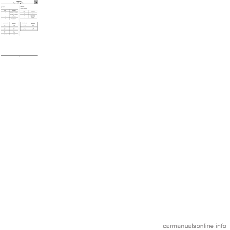
Test to be made
between tracksResistance
1 - 2 1.5 Ω
1 - 3 1 Ω
1 - 4 1 Ω
2 - 3 1 Ω
2 - 4 1 Ω
3 - 4 0.6 Ω
HT - HT8 kΩ
D7F Engine
Electrical connector
Track Allocation
1coil control for cylinders
1-4
2coil control for cylinders
3-2
3 +after ignition
4+anti-interference
condenser
Test to be made
between tracksResistance
1 - 2 0.5 Ω
1 - 3 1 Ω
2 - 3 1 Ω
HT - HT10 kΩ
Track Allocation
1+anti-interference
condenser
2 +after ignition
3coil control by
computer
D7F Engine
Electrical connector
17-2
Page 154 of 208
INJECTION
General
17
SPECIAL NOTES FOR MULTIPOINT INJECTION
• 35 track SAGEM or MAGNETI MARELLI computer for vehicles without options.
• 55 track SAGEM computer ,
SAFIR or MAGNETI MARELLI type for versions with air conditioning.
•Semi-sequential multipoint injection. Injectors controlled two by two (injectors for cylinders 1 and 4 fol-
lowed by injectors for cylinders 2 and 3).
•Semi-static ignition with dual single unit coils.
•Canister bleed solenoid valve controlled by RCO signal.
•Computer configuration depending on gearbox type (manual gearbox or automatic transmission).
•The maximum engine speed permitted is 6 200 rpm.
•Idle speed correction depending on :
- battery voltage,
- air conditioning
- power assisted steering pressostat.
•Injection warning light on instrument panel not operational.
•Use fault finding fiche n° 27. D7F Engine
FITTING A 2ND GENERATION ENGINE IMMOBILISER REQUIRES A SPECIAL PROCEDURE FOR REPLACING THE
COMPUTER.
17-4
Page 155 of 208
INJECTION
General
17
SPECIAL NOTES FOR MULTIPOINT INJECTION
• 55 track SIEMENS FENIX 5 computer.
•Semi-sequential multipoint injection. Injectors are controlled two by two (injectors for cylinders 1 and 4
followed by cylinders 2 and 3).
•Semi-static ignition with dual coils.
•Canister bleed solenoid controlled by RCO signal.
•Computer configuration depending on gearbox type (manual gearbox or automatic transmission)
•Idle speed correction depending on :
- air conditioning,
- power assisted steering pressostat,
- battery voltage.
•Injection warning light on instrument panel operational.
•Use fault finding fiche n° 27.
•Maximum speed :
-6 200 rpm if 1st , 2nd or 3rd gears
-6 000 rpm if 4th,or 5th gears. E7J Engine
FITTING A 2ND GENERATION ENGINE IMMOBILISER REQUIRES A SPECIAL PROCEDURE FOR REPLACING THE
COMPUTER.
17-5
Page 156 of 208
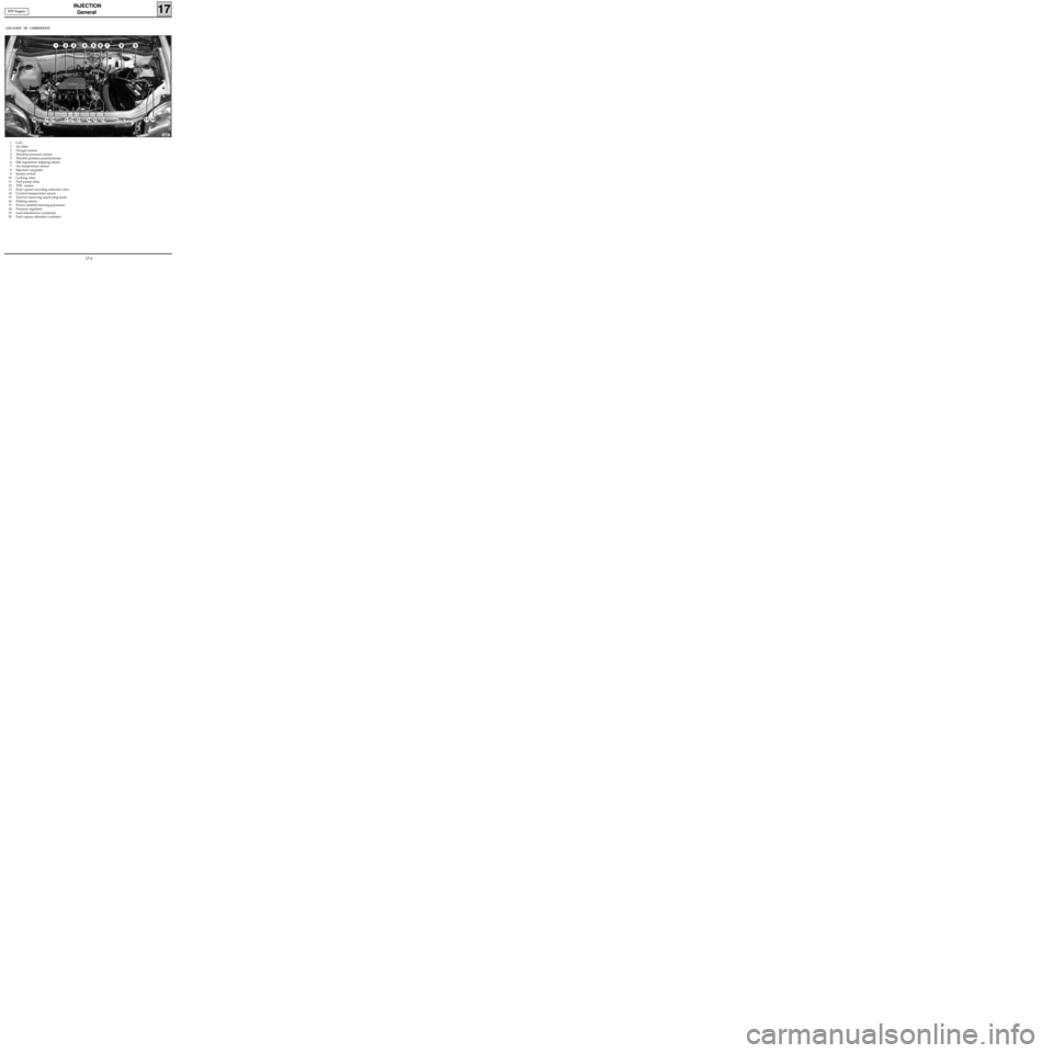
INJECTION
General
17
1 Coil
2 Air filter
3 Oxygen sensor
4 Absolute pressure sensor
5 Throttle position potentiometer
6 Idle regulation stepping motor
7 Air temperature sensor
8 Injection computer
9 Inertia switch
10 Locking relay
11 Fuel pump relay
12 TDC sensor
13 Fuel vapour recycling solenoid valve
14 Coolant temperature sensor
15 Tool for removing spark plug leads
16 Pinking sensor
17 Power assisted steering pressostat
18 Pressure regulator
19 Anti-interference condenser
20 Fuel vapour absorber (canister)
LOCATION OF COMPONENTS
13081
D7F Engine
17-6