catalytic converter RENAULT KANGOO 1997 KC / 1.G Engine And Peripherals Workshop Manual
[x] Cancel search | Manufacturer: RENAULT, Model Year: 1997, Model line: KANGOO, Model: RENAULT KANGOO 1997 KC / 1.GPages: 208
Page 19 of 208
ENGINE AND ENGINE PERIPHERALS
Engine and transmission assembly
10
13085R
- the exhaust heat shield and the gear control
on the lever and gearbox sides,
12988R
- the exhaust pipe clamp between the catalytic
converter and the expansion chamber,
- the earth strap on the gearbox,
- the front bumper,
- the air intake pipe from the air filter,
- the injection computer support after dis-
connecting the 55 track connector and that of
the impact switch.
13088R2
Disconnect:
- the wiring connections and the hoses on the
thermostat support,
- the hoses on the expansion bottle,
- the brake servo pipe,
- the heater hoses (there are two types of as-
sembly to be disconnected, as shown in the
diagrams below),
13084R
E7J engine
10-15
Page 30 of 208
ENGINE AND ENGINE PERIPHERALS
Sump
10
Front sub-frame mounting bolt 6.2
Rear sub-frame mounting bolt 10.5
E7J sump bolt 1
F8Q sump bolt 1.5
Steering shaft yoke mounting bolt 3
Engine tie-bar bolt 6.2
Wheel bolt 9
TIGHTENING TORQUES (in daN.m)
REMOVAL
Put the vehicle on a 2 post lift.
Disconnect the battery.
Drain the engine oil.
Remove:
- the front wheels,
- the nut and the eccentric bolt of the steering
shaft yoke, after pushing back the guard,
97390S1
- the lower ball joint mountings and the track
rod ends for the
E7J engine,
- the sub-frame and body tie rods,
- the gear control on the gearbox side,
- bolt (1), and slacken engine tie-bar bolt (2),
without removing it,
E7J / F8Q
engines
SPECIAL TOOLING REQUIRED
Mot. 1233-01 Threaded rods for lowering the
sub-frame
13359R1
- the bottom mountings of the bumper,
- the exhaust downpipe for the
F8Q engine.
Special notes for the E7J engine
Remove:
- the exhaust manifold heat shield,
- the catalytic converter,
- the engine flywheel guard,
- the power assisted steering pipe mountings
on the cylinder block and the multifunction
mounting.
10-26
Page 66 of 208
FUEL MIXTURE
Specifications
12
Vehicle GearboxEngine
Type SuffixBore
(mm)Stroke
(mm)Capacity
(cm
3)RatioCatalytic
converterDepollut-
ion
standard
XC0A JB1 D7F 710 69 76.8 1149 9.65/1 C61 EU 96
Temperature in °C (± 1°) 0 20 40 80 90
Air temperature sensor
Type CTN
Resistance in Ohms5000 to 7000 1700 to 3300 800 to 1550 - -
Coolant temperature sensor
Type CTN
Resistance in Ohms6700 to 8000 2600 to 3000 1100 to 1300 270 to 300 200 to 215
Engine
Type SuffixTests at idle speed*
Engine
speed
[rpm]Pollutant emission **
CO (%) (1) CO
2 (%) HC (ppm) Lambda (λ)Fuel***
[minimum octane
rating]
D7F 710 740±50 0.5 max 14.5 min 100 max 0.97<λ<1.03 Unleaded (OR 95)
(1) at 2500 rpm, CO must be a maximum of 0.3
* For a coolant temperature above 80°C and after stable speed of 2500 rpm, for about 30 seconds. Test to
be carried out after return to idle speed.
** For legal values refer to your country specification.
*** OR 91 unleaded compatible.D7F engine
12-1
Page 69 of 208
FUEL MIXTURE
Specifications
12
Vehicle GearboxEngine
Type SuffixBore
(mm)Stroke
(mm)Capacity
(cm
3)RatioCatalytic
converterDepollu-
tion
standard
XC0C Manual E7J 780 75.8 77 1390 9.5/1 C63 EU 96
Temperature in °C (± 1°) 0 20 40 80 90
Air temperature sensor
Type CTN
Resistance in Ohms7470 to
119703060 to 4045 1315 to 1600 - -
Coolant temperature sensor
Type CTN
Resistance in Ohms6700 to 8000 2600 to 3000 1100 to 1300 270 to 300 200 to 215
Engine
Type SuffixTests at idle speed*
Engine
speed
[rpm]Pollutant emission **
CO (%) (1) CO
2 (%) HC (ppm) Lambda (λ)Fuel***
(minimum octane
rating)
E7J 780 750±50 0.5 max 14.5 min 100 max 0.97<λ<1.03 Unleaded (OR 95)
(1) at 2500 rpm, CO must be a maximum of 0.3
* For a coolant temperature above 80°C and after stable speed of 2500 rpm, for about 30 seconds. Test to
be carried out after return to idle speed.
** For legal values refer to your country specification.
*** OR 91 unleaded compatible.E7J engine
12-4
Page 94 of 208
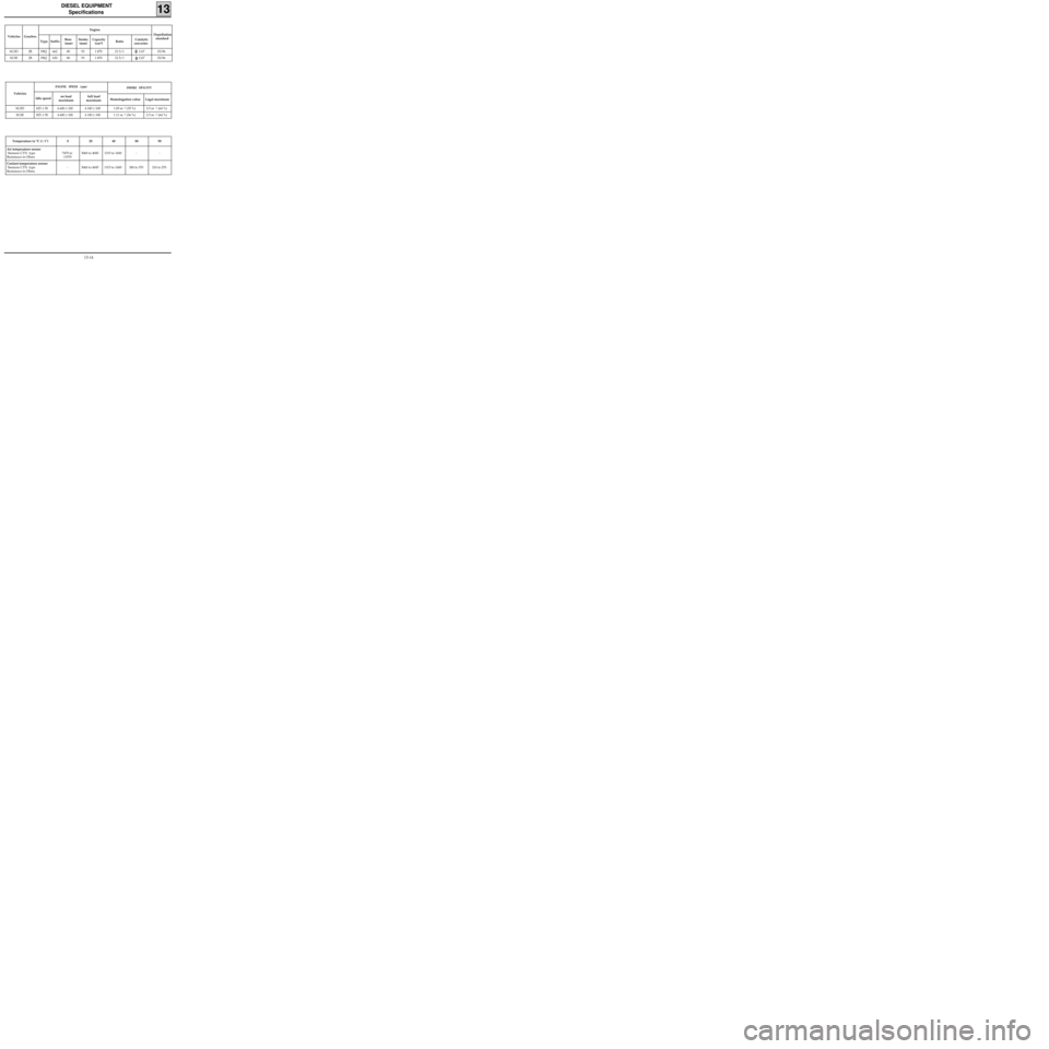
DIESEL EQUIPMENT
Specifications
13
Vehicles GearboxEngine
Type SuffixBore
(mm)Stroke
(mm)Capacity
(cm
3)RatioCatalytic
converterDepollution
standard
XC0D JB F8Q 662 80 93 1 870 21.5/1 C67 EU96
XC0E JB F8Q 630 80 93 1 870 21.5/1 C67 EU96
Vehicles
ENGINE SPEED (rpm)
Idle speedno load
maximumfull load
maximum
SMOKE OPACITY
Homologation value Legal maximum
XC0D 825 ± 50 4 600 ± 100 4 100 ± 100 1.05 m
-1 (35 %) 2.5 m -1 (64 %)
XC0E 825 ± 50 4 600 ± 100 4 100 ± 100 1.11 m
-1 (36 %) 2.5 m -1 (64 %)
Temperature in °C (± 1°) 0 20 40 80 90
Air temperature sensor
Siemens CTN type
Resistance in Ohms7470 to
119703060 to 4045 1315 to 1600 - -
Coolant temperature sensor
Siemens CTN type
Resistance in Ohms- 3060 to 4045 1315 to 1600 300 to 370 210 to 270
13-14
Page 186 of 208
EXHAUST
General
19
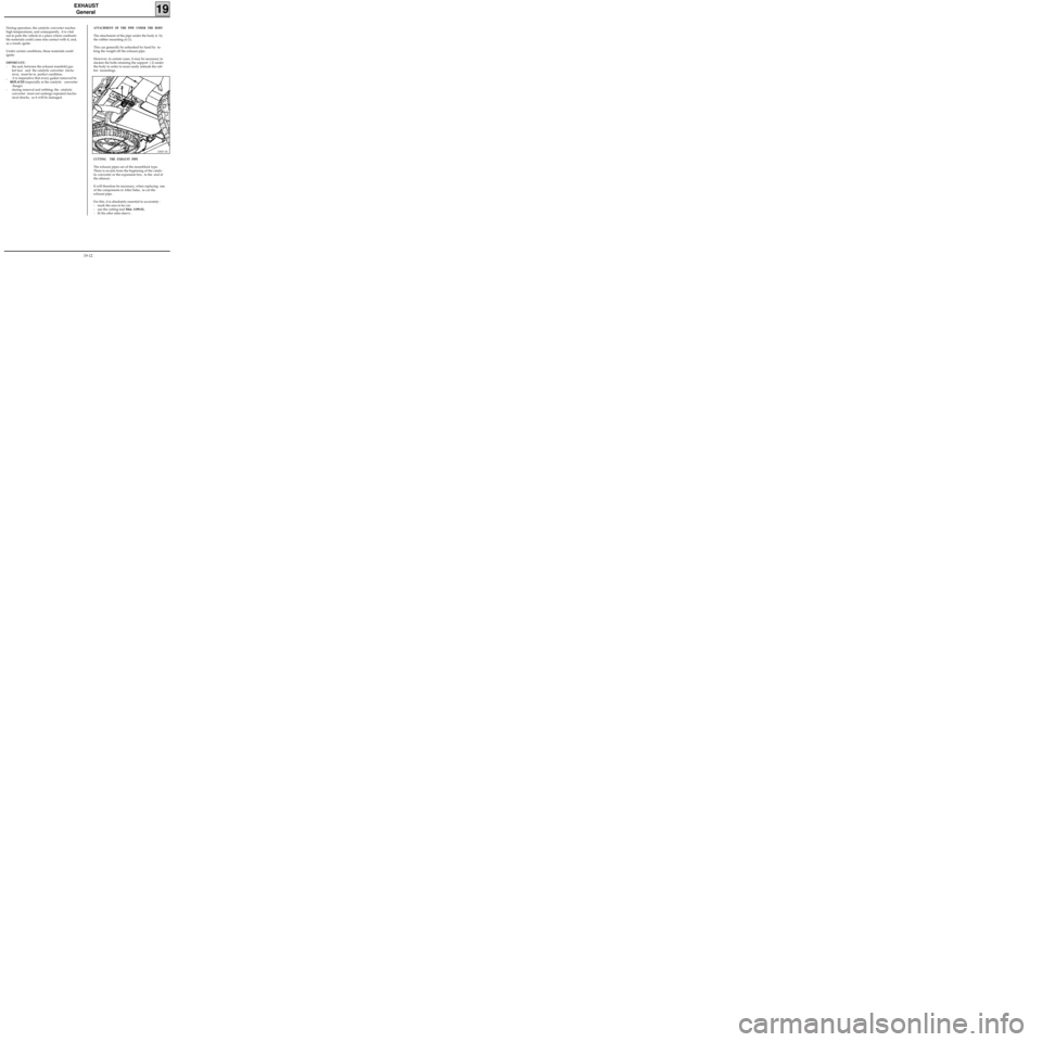
ATTACHMENT OF THE PIPE UNDER THE BODY
The attachment of the pipe under the body is by
the rubber mounting at (1).
This can generally be unhooked by hand by ta-
king the weight off the exhaust pipe.
However, in certain cases, it may be necessary to
slacken the bolts retaining the support ( 2) under
the body in order to more easily unhook the rub-
ber mountings. During operation, the catalytic converter reaches
high temperatures, and consequently, it is vital
not to park the vehicle in a place where combusti-
ble materials could come into contact with it, and,
as a result, ignite.
Under certain conditions, these materials could
ignite.
IMPORTANT:
- the seal, between the exhaust manifold gas-
ket face and the catalytic converter (inclu-
sive), must be in perfect condition,
_ it is imperative that every gasket removed be
REPLACED (especially at the catalytic converter
flange)
- during removal and refitting, the catalytic
converter must not undergo repeated mecha-
nical shocks, as it will be damaged.
CUTTING THE EXHAUST PIPE
The exhaust pipes are of the monoblock type.
There is no join from the beginning of the cataly-
tic converter or the expansion box, to the end of
the silencer.
It will therefore be necessary, when replacing one
of the components in After Sales, to cut the
exhaust pipe.
For this, it is absolutely essential to accurately :
- mark the area to be cut,
- use the cutting tool Mot. 1199-01,
- fit the after sales sleeve .
12847-1R
19-12
Page 187 of 208
EXHAUST
General
19
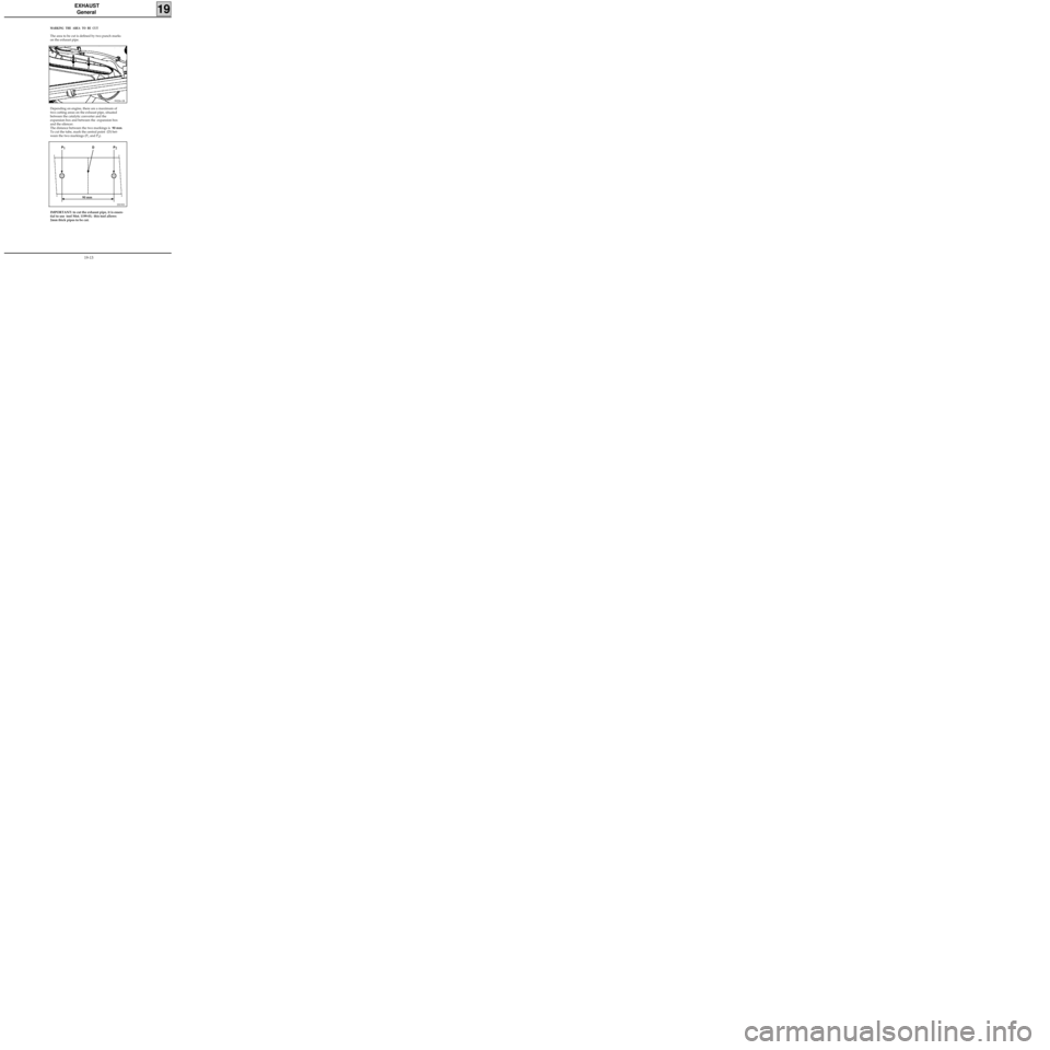
MARKING THE AREA TO BE CUT
The area to be cut is defined by two punch marks
on the exhaust pipe.
99226-1R
Depending on engine, there are a maximum of
two cutting areas on the exhaust pipe, situated
between the catalytic converter and the
expansion box and between the expansion box
and the silencer.
The distance between the two markings is 90 mm.
To cut the tube, mark the central point (D) bet-
ween the two markings (P
1 and P2).
DI1901
90 mm
P
1P
2 D
IMPORTANT: to cut the exhaust pipe, it is essen-
tial to use tool Mot. 1199-01; this tool allows
2mm thick pipes to be cut.
19-13
Page 189 of 208
EXHAUST
Pipe assembly
19
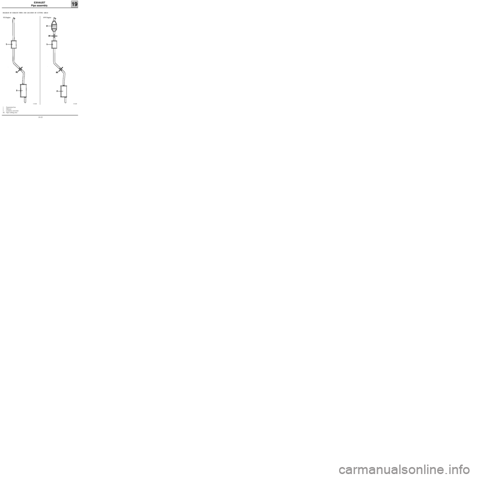
DIAGRAM OF EXHAUST PIPES AND LOCATION OF CUTTING AREAS
1 Expansion box
2 Silencer
3 Catalytic converter
ZC Pipe cutting area
13124R
E7J Engine D7F Engine
13126R
19-15
Page 190 of 208
EXHAUST
Pipe assembly
19
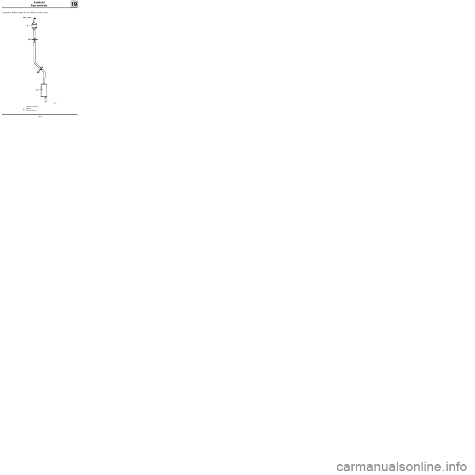
DIAGRAM OF EXHAUST PIPES AND LOCATION OF CUTTING AREAS
13125R
1 Catalytic converter
2 Silencer
ZC Pipe cutting area F8Q Engine
19-16
Page 202 of 208
FUEL TANK
Fuel tank
19
PURPOSE OF THE VALVES
28 Overfill prevention valve
When the filler cap is removed the valve is
closed, trapping a volume of air within the
breather volume. This prevents fuel from fil-
ling this volume.
When the filler cap is replaced, the valve
opens allowing the tank to breathe through
the canister
29 Excess - vacuum safety valve
If the fuel vapour recirculation circuit is
blocked, this valve prevents the fuel tank
being subject to excess pressure (the tank
would inflate) or vacuum (as fuel is used, the
tank would be crushed).
30 Restriction valve
This valve prevents the introduction of leaded
fuel into the tank.
31 Leak prevention valve in case vehicle turns
over
If the vehicle turns over, this valve prevents
the tank from emptying, either through the
pipe leading to the canister, or through the
breather pipe (in Diesel versions).
32 Overfill prevention valve and leak prevention
valve in case the vehicle turns over
The overfill prevention valve operates using
the ball at (33).
When the vehicle is stationary, during filling,
the ball rests in its seat, retaining a certain
volume of air in the reservoir .
When the vehicle is moving , the ball (33)
moves out of its seat, thus allowing the tank
to be connected to the canister.
When the tank is full, it is vital that a
sufficient volume of air to allow the fuel
contained within it to expand is retained
inside the tank, but not too much, otherwise
there is a risk of the tank exploding .
This valve has the same operating principle as
the valve (31) .
The tank has a sealed cap.
The filler neck for unleaded petrol has the follo-
wing special features :
- a filling opening with a smaller diameter and
not compatible with a conventional filling
nozzle (the lead would have the effect of pol-
luting the depollution system: oxygen sensor
and catalytic converter),
- a valve blocking the filing opening (30) (to
avoid fuel evaporating or the reverse passage
of fuel).
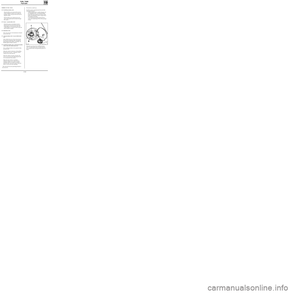
Fitting the cap releases the overfill prevention
valve (A) allowing the tank to breathe (this fea-
ture is present only in first generation petrol ver-
sions).
99212R2
19-28