clock RENAULT KANGOO 1997 KC / 1.G Engine And Peripherals Workshop Manual
[x] Cancel search | Manufacturer: RENAULT, Model Year: 1997, Model line: KANGOO, Model: RENAULT KANGOO 1997 KC / 1.GPages: 208
Page 38 of 208
TOP AND FRONT OF ENGINE
Timing belt
11
REFITTING
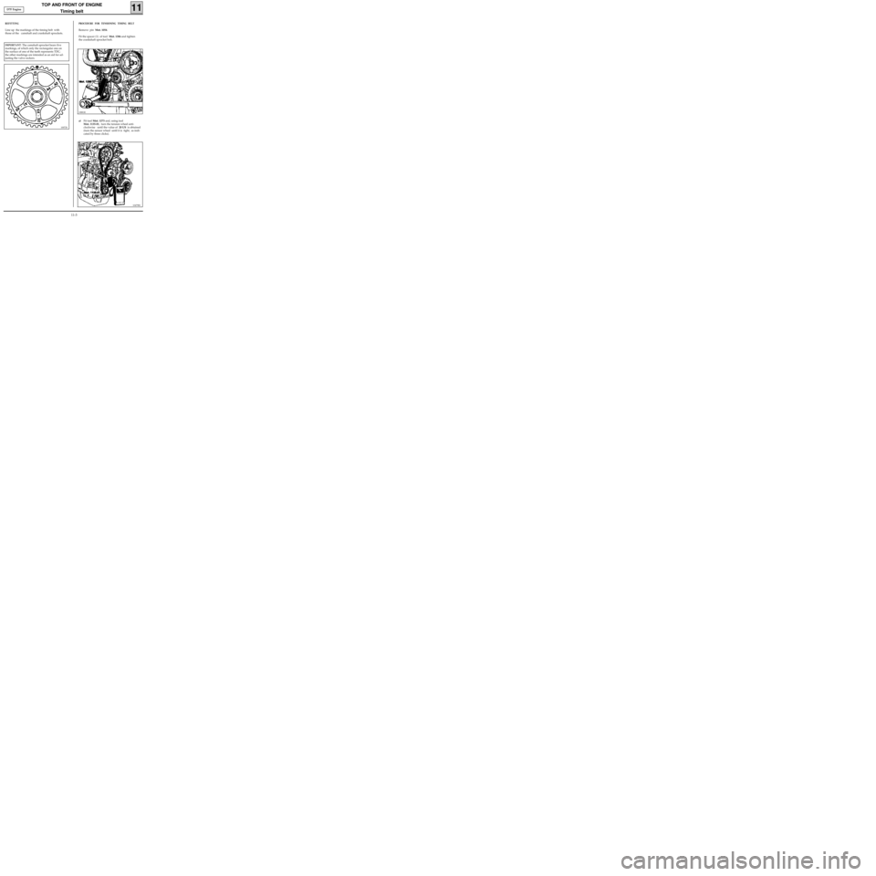
Line up the markings of the timing belt with
those of the camshaft and crankshaft sprockets.
10072S
PROCEDURE FOR TENSIONING TIMING BELT
Remove pin Mot. 1054.
Fit the spacer (1) of tool Mot. 1386 and tighten
the crankshaft sprocket bolt.
10881R
a)Fit tool Mot. 1273 and, using tool
Mot. 1135-01, turn the tension wheel anti-
clockwise until the value of 20 US is obtained
(turn the sensor wheel until it is tight, as indi-
cated by three clicks).
10479R1
IMPORTANT: The camshaft sprocket bears five
markings, of which only the rectangular one on
the surface of one of the teeth represents TDC;
the other markings are intended as an aid for ad-
justing the valve rockers.
D7F Engine
11-3
Page 39 of 208
TOP AND FRONT OF ENGINE
Timing belt
11
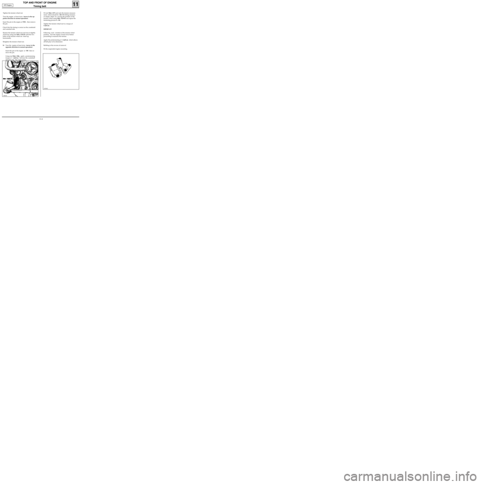
Tighten the tension wheel nut.
Turn the engine at least twice (never in the op-
posite direction to normal operation).
Insert the pin in the engine at TDC, then remove
the pin .
Check that the timing is correct on the crankshaft
and camshaft side.
Slacken the tension wheel nut and turn it slightly
clockwise using tool Mot. 1135-01 until the two
holes of the tension wheel are lined up
horizontally.
Retighten the tension wheel nut.
b)Turn the engine at least twice (never in the
opposite direction to normal operation).
Insert the pin in the engine at
TDC then re-
move the pin.
Using tool Mot. 1386, apply a pretensioning
torque of 1 daN.m between the crankshaft
sprocket and the water pump.
Fit tool Mot. 1273 and note the tension measure-
ment, which should be 20±
3 US (fitting tension),
or simply adjust by varying the position of the
tension wheel using Mot. 1135-01 and repeat the
tensioning process in (b).
Tighten the tension wheel nut to a torque of
5 daN.m.
IMPORTANT
Following each variation of the tension wheel
position, turn the engine at least twice before
proceeding to measure the tension .
Apply the pretensioning of 1 daN.m which allows
all belt play to be eliminated.
Refitting is the reverse of removal.
Fit the suspended engine mounting .
12924S1
10881R
D7F Engine
11-4
Page 51 of 208
TOP AND FRONT OF ENGINE
Cylinder head gasket
11
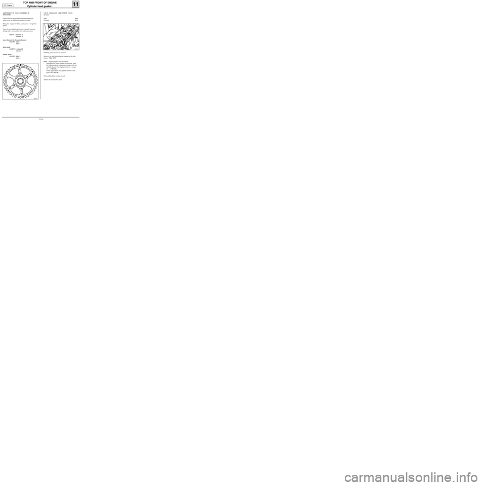
ADJUSTMENT OF VALVE ROCKERS (IF
NECESSARY)
Partly refit the suspended engine mounting ti-
ming cover on the engine using two bolts.
Bring the engine to TDC , cylinder n. 1 in ignition
phase .
Turn the crankshaft clockwise (viewed from the
timing side ) to reach the first reference mark.
ADJUST :exhaust 1
exhaust 3
move forward to the second mark :
ADJUST:inlet 1
inlet 3
third mark :
ADJUST: exhaust 2
exhaust 4
fourth mark :
ADJUST:inlet 2
inlet 4
10072S
99905S
Refitting is the reverse of removal.
Remove the tool retaining the engine on the sub-
frame, Mot. 1379.
NOTE : tightening the inlet manifold :
- progressively hand tighten the six nuts until
the inlet manifold comes into contact with the
cylinder head, then tighten them to a torque
of 1.5 daN.m,
- fit the upper bolts and tighten them to a tor-
que of 0.9 daN.m.
Fill and bleed the cooling circuit.
Adjust the accelerator cable.
VALVE CLEARANCE ADJUSTMENT VALUE
(in mm)
Inlet0.05
Exhaust0.15 D7F Engine
11-16
Page 124 of 208
DIESEL EQUIPMENT
Pump - Timing
13
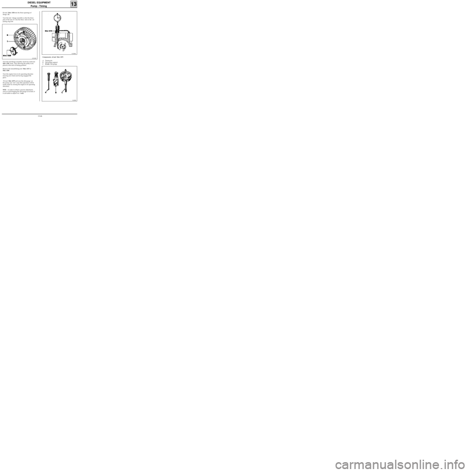
Fit tool Mot. 1358 into the three openings of
flange (B).
Turn the tool - flange assembly so that the three
pins of the tool fit into the three slots in the ad-
justing ring bolt.
12312R2
Turn the tool-flange assembly clockwise until tool
Mot. 1358 locks, thus allowing the pulley to be
placed at the start of timing position .
Remove the immobilising tool Mot. 1317 or
Mot. 1200.
Turn the engine twice in its operating direction
(moving one wheel and having engaged 5th
gear).
Fit tool Mot. 1079 and zero the dial gauge on
the pump cam "rest" zone (this operation will be
made easier by turning the engine in its operating
direction).
NOTE : in order to obtain a precise adjustment,
and to avoid bringing the dial gauge to its limit, it
is advisable to adjust it to 1 mm.
91258R2
Components of tool Mot. 1079
A Timing pin
B Dial gauge support
C30 mm dial gauge
91285R
13-44
Page 125 of 208
DIESEL EQUIPMENT
Pump - Timing
13
DI1303-1
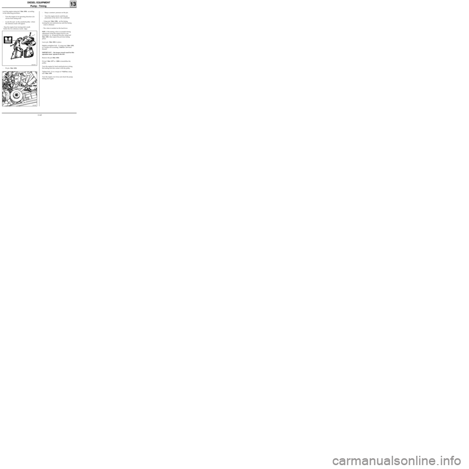
- Fit pin Mot. 1054.
12419R
- Keep a constant pressure on the pin.
- Turn the engine slowly until the pin
penetrates in the slot in the crankshaft.
- Using tool Mot. 1358, set the timing,
turning the tool anticlockwise until the timing
value is obtained.
- The value is marked on the load lever.
NOTE : if the timing value is exceeded during
adjustment, bring the engine back by one
revolution , to recuperate the play using tool
Mot. 1358 , then repeat the previous timing
phase.
Leave pin Mot. 1054 in place.
Slightly pretighten bolt (1) using tool Mot. 1359,
to a torque not exceeding 2 daN.m (left hand
thread).
IMPORTANT : the torque wrench used for this
operation must operate to the left .
Remove the pin Mot. 1054.
Fit tool Mot. 1377 or 1200 to immobilise the
pulley.
Turn the engine by hand anticlockwise to bring
the locking tool into contact with the pulley.
Tighten bolt (1) to a torque of 9 daN.m, using
tool Mot. 1359.
Turn the engine over twice and check the pump
timing once again.
Lock the engine using tool Mot. 1054, according
to the following procedure :
- Turn the engine in its operating direction (clo-
ckwise from timing end).
- Locate the spot on the camshaft pulley where
the reference mark will appear .
- Stop the engine from turning half a tooth
before the two reference marks align.
13-45