engine RENAULT KANGOO 1997 KC / 1.G Foult Finding - Injection Workshop Manual
[x] Cancel search | Manufacturer: RENAULT, Model Year: 1997, Model line: KANGOO, Model: RENAULT KANGOO 1997 KC / 1.GPages: 363
Page 143 of 363
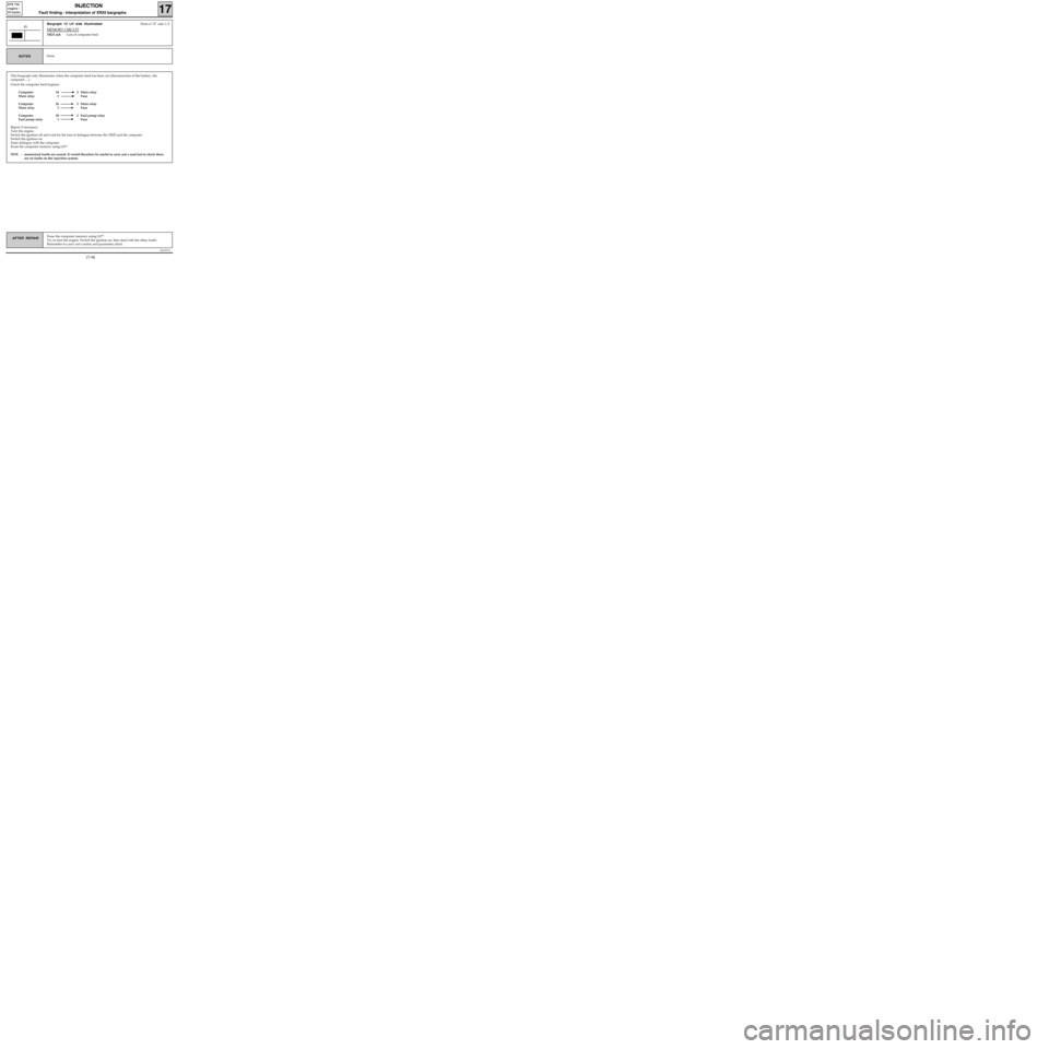
This bargraph only illuminates when the computer feed has been cut (disconnection of the battery, the
computer, ...).
Check the computer feed hygiene:
Computer 18 5 Main relay
Main relay 3 Fuse
Computer 26 2 Main relay
Main relay 1 Fuse
Computer 20 2 Fuel pump relay
Fuel pump relay 1 Fuse
Repair if necessary.
Turn the engine.
Switch the ignition off and wait for the loss of dialogue between the XR25 and the computer.
Switch the ignition on.
Enter dialogue with the computer.
Erase the computer memory using G0**.
NOTE :memorised faults are erased. It would therefore be useful to carry out a road test to check there
are no faults on the injection system.
JSA051.0
INJECTION
Fault finding - Interpretation of XR25 bargraphs17
D7F 710
engine -
35 tracks
Erase the computer memory using G0**.
Try to start the engine. Switch the ignition on, then deal with the other faults.
Remember to carry out a status and parameter check.AFTER REPAIR
Bargraph 13 LH side illuminatedFiche n° 27 side 1/2
MEMORY CIRCUIT
XR25 aid:Loss of computer feed
13
NoneNOTES
17-98
Page 144 of 363
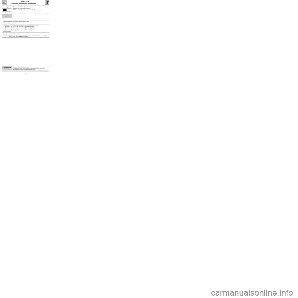
Check the insulation, continuity and that there is no interference resistance on the line:
Computer 11 D idle speed regulation stepping motor
Computer 12 A idle speed regulation stepping motor
Computer 28 B idle speed regulation stepping motor
Computer 29 C idle speed regulation stepping motor
Repair if necessary.
JSA051.0
INJECTION
Fault finding - Interpretation of XR25 bargraphs17
D7F 710
engine -
35 tracks
Erase the computer memory using G0**.
Try to start the engine. Switch the ignition on, then deal with the other faults.
Remember to carry out a status and parameter check.AFTER REPAIR
Bargraph 14 LH side illuminatedFiche n° 27 side 1/2
IDLE SPEED REGULATION CIRCUIT
XR25 aid:CO, CC- or CC+ line 11 or 12 or 28 or 29 on the computer
14
NoneNOTES
Check the resistance of the idle speed regulation stepping motor.
Check the idle speed regulation valve if necessary.
The fault persists! Replace the injection computer.
IMPORTANT: The computer has probably been damaged by an electric shock. The cause of the damage
must be found before fitting a new computer.
17-99
Page 145 of 363
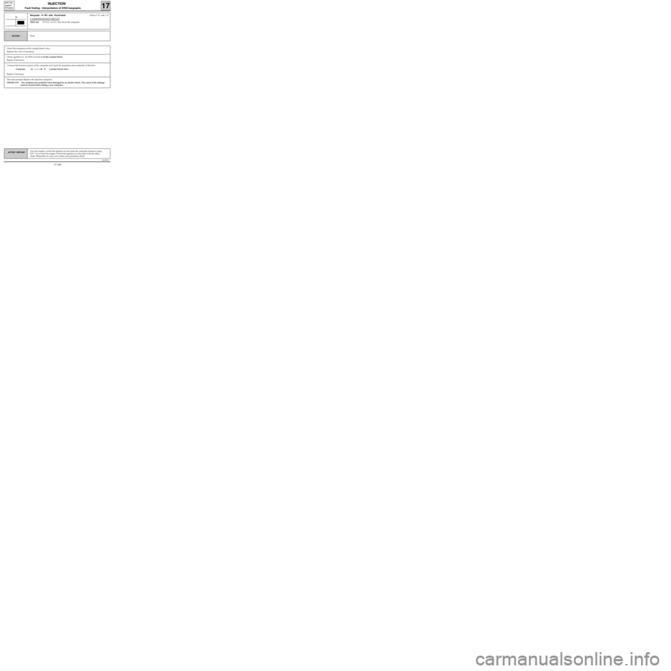
Connect the bornier in place of the computer and check the insulation and continuity of the line:
Computer 24 B Canister bleed valve
Repair if necessary.
JSA051.0
INJECTION
Fault finding - Interpretation of XR25 bargraphs17
D7F 710
engine -
35 tracks
Turn the engine, switch the ignition on and erase the computer memory using
G0**. Try to start the engine. Switch the ignition on, then deal with the other
faults. Remember to carry out a status and parameter check.AFTER REPAIR
Bargraph 14 RH side illuminatedFiche n° 27 side 1/2
CANISTER BLEED CIRCUIT
XR25 aid:CO, CC- or CC+ line 24 on the computer
14
NoneNOTES
Check the resistance of the canister bleed valve.
Replace the valve if necessary.
Check, ignition on , for 12 V on track A of the canister bleed.
Repair if necessary.
The fault persists! Replace the injection computer.
IMPORTANT: The computer has probably been damaged by an electric shock. The cause of the damage
must be found before fitting a new computer.
17-100
Page 146 of 363
JSA051.0
INJECTION
Fault finding - Interpretation of XR25 bargraphs17
D7F 710
engine -
35 tracks
Erase the computer memory using G0**.
Try to start the engine. Switch the ignition on, then deal with the other faults.
Remember to carry out a status and parameter check.AFTER REPAIR
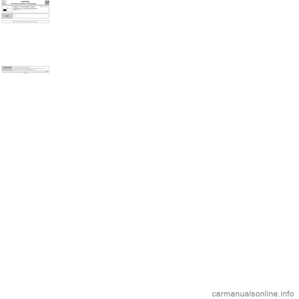
Bargraph 15 LH side illuminated or flashingFiche n° 27 side 1/2
COMPUTER AC CONNECTION CIRCUIT
XR25 aid:None
15
NoneNOTES
Ignore the illumination of this bargraph with this computer.
17-101
Page 147 of 363
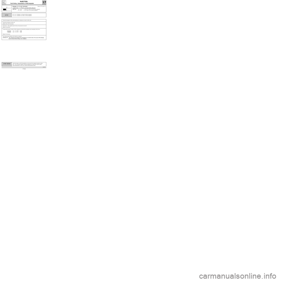
Connect the bornier in place of the computer and check the insulation and continuity of the line :
Computer 17 2 Coil
Computer 35 1 Coil
Repair if necessary.
JSA051.0
INJECTION
Fault finding - Interpretation of XR25 bargraphs17
D7F 710
engine -
35 tracks
Turn the engine, switch the ignition on and erase the computer memory using
G0**. Try to start the engine. Switch the ignition on, then deal with the other
faults. Remember to carry out a status and parameter check.AFTER REPAIR
Bargraph 16 LH side illuminatedFiche n° 27 side 1/2
COMPUTER MPA CONNECTION CIRCUIT
XR25 aid:*16 = XX.CO=> CO or CC- line 17 or 35 of the computer
*16 = XX.CC=> CC+ line 17 or 35 of the computer
16
XX = 14 => Cylinder 1 or 4 line 35 of the computer
XX = 23 =
> Cylinder 2 or 3 line 17 of the computerNOTES
Check the resistance of the coil.
Replace the coil if necessary.
Check the + after ignition feed to the coil concerned on track 3.
Repair if necessary.
The fault persists! Replace the injection computer.
IMPORTANT: The computer has probably been damaged by an electric shock. The cause of the damage
must be found before fitting a new computer.
Check the hygiene of the anti-interference condenser on track 4 of the coil.
17-102
Page 148 of 363
JSA051.0
INJECTION
Fault finding - Status and parameter checks
17
D7F 710
engine -
35 tracks
Engine cold, ignition on.NOTES
Order of
operationsFunction to be
checkedAction Bargraph Display and notes Fault finding
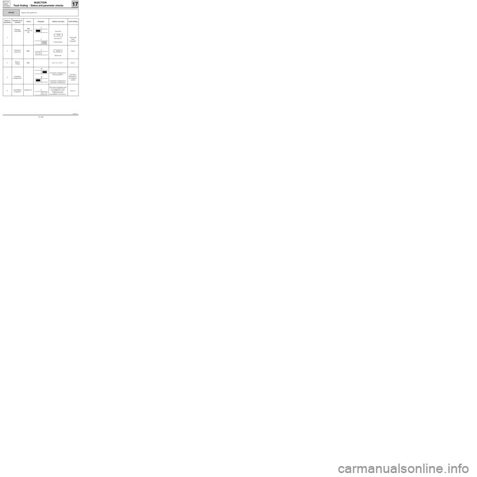
1Dialogue
with XR25D13
(selector on
S8)Fault test
9.NJ
Use fiche 27
Code present
Deal with
fault
bargraph
2Change to
status testG01*
10.NJ
Status testNone
3Battery
voltage# 0411.8 < X < 13.2 V
DIAG 1
4Computer
configurationComputer configured to
manual gearbox
Computer configured to
automatic transmissionSee Fiche
"Reminder C"
to configure
vehicle
5Immobiliser
(if option)Ignition onThis status bargraph must
be extinguished when
the ignition is on to
indicate that the
immobiliser is not active.
DIAG 12
1
19
19
1
1
3
17-103
Page 149 of 363
JSA051.0
INJECTION
Fault finding - Status and parameter checks
17
D7F 710
engine -
35 tracks
Engine cold, ignition on.NOTES
Order of
operationsFunction to be
checkedAction Bargraph Display and notes Fault finding
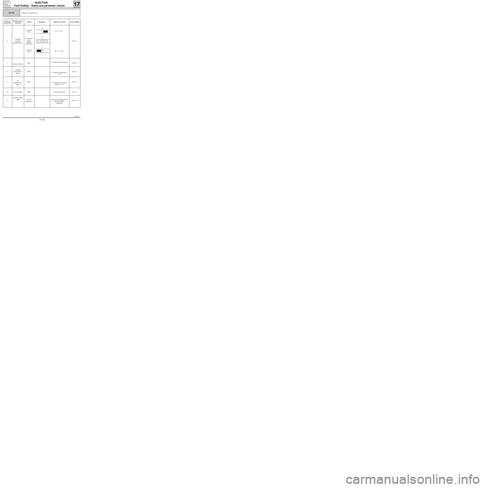
6Throttle
position
potentiometer
.No load
# 17
Accelerator
pedal
slightly
depressed
Full load
# 1710 < X < 50
185 < X < 245
DIAG 2
7
Pressure sensor# 01X =Atmospheric pressureDIAG 9
8Coolant
temperature
sensor# 02
X = Engine temperature
± 5 °CDIAG 3
9Air
temperature
sensor# 03
X = Temperature under
bonnet ± 5 °CDIAG 4
10 Fan assemblyG17*Fan must operateDIAG 16
11Fault warning
light Switch
ignition onFault warning light must
illuminate then
extinguishDIAG 18
2
2
2
17-104
Page 150 of 363
Order of
operationsFunction to be
checkedAction Bargraph Display and notes Fault finding
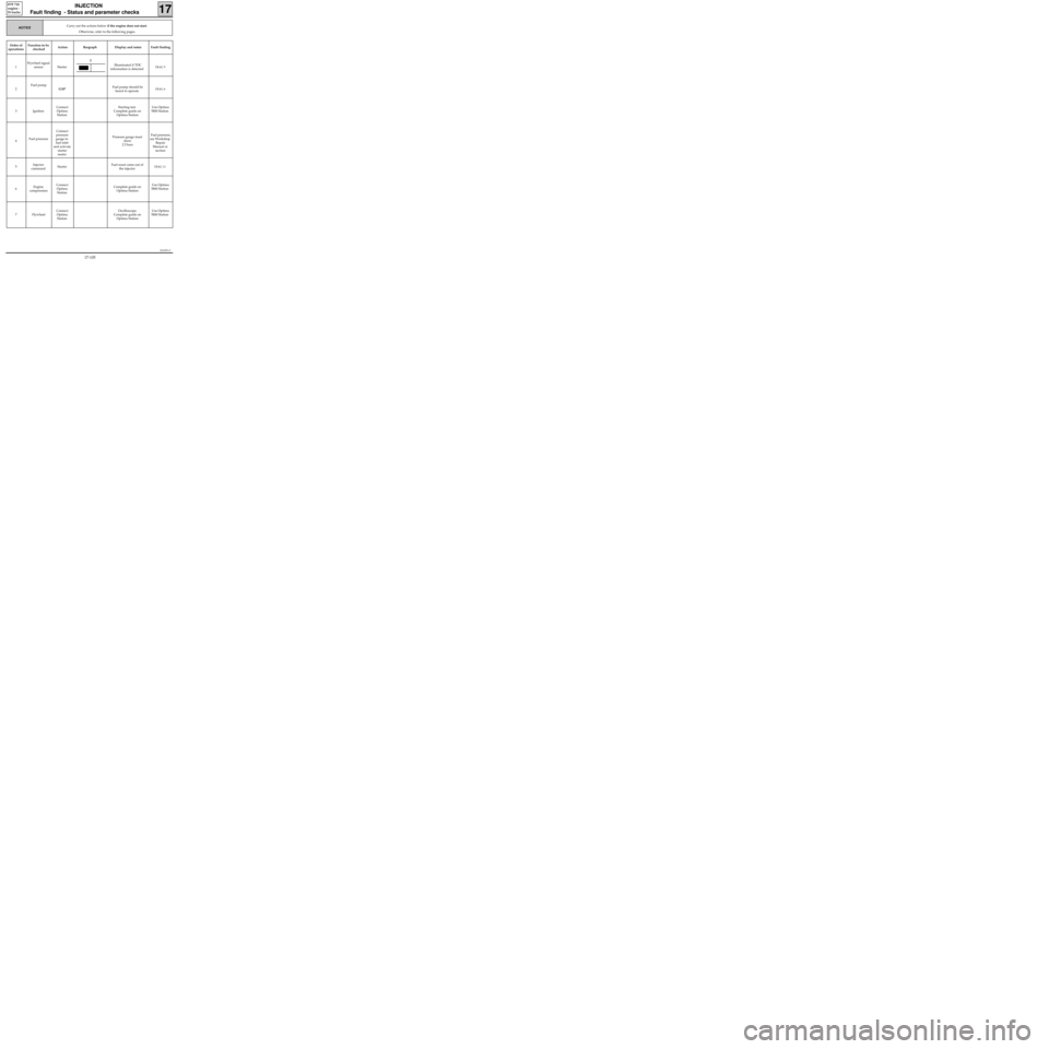
1Flywheel signal
sensor StarterIlluminated if TDC
information is detected
DIAG 5
2Fuel pump
G10*Fuel pump should be
heard to operateDIAG 6
3 IgnitionConnect
Optima
StationStarting test.
Complete guide on
Optima StationUse Optima
5800 Station
4Fuel pressureConnect
pressure
gauge to
fuel inlet
and activate
starter
motorPressure gauge must
show
2.5 bars Fuel pressure,
see Workshop
Repair
Manual or
section
5Injector
commandStarterFuel must come out of
the injector
DIAG 11
6Engine
compressionConnect
Optima
StationComplete guide on
Optima StationUse Optima
5800 Station
7 FlywheelConnect
Optima
StationOscilloscope.
Complete guide on
Optima StationUse Optima
5800 Station
JSA051.0
INJECTION
Fault finding - Status and parameter checks
17
D7F 710
engine -
35 tracks
Carry out the actions below if the engine does not start.
Otherwise, refer to the following pages.NOTES
3
17-105
Page 151 of 363
JSA051.0
INJECTION
Fault finding - Status and parameter checks
17
D7F 710
engine -
35 tracks
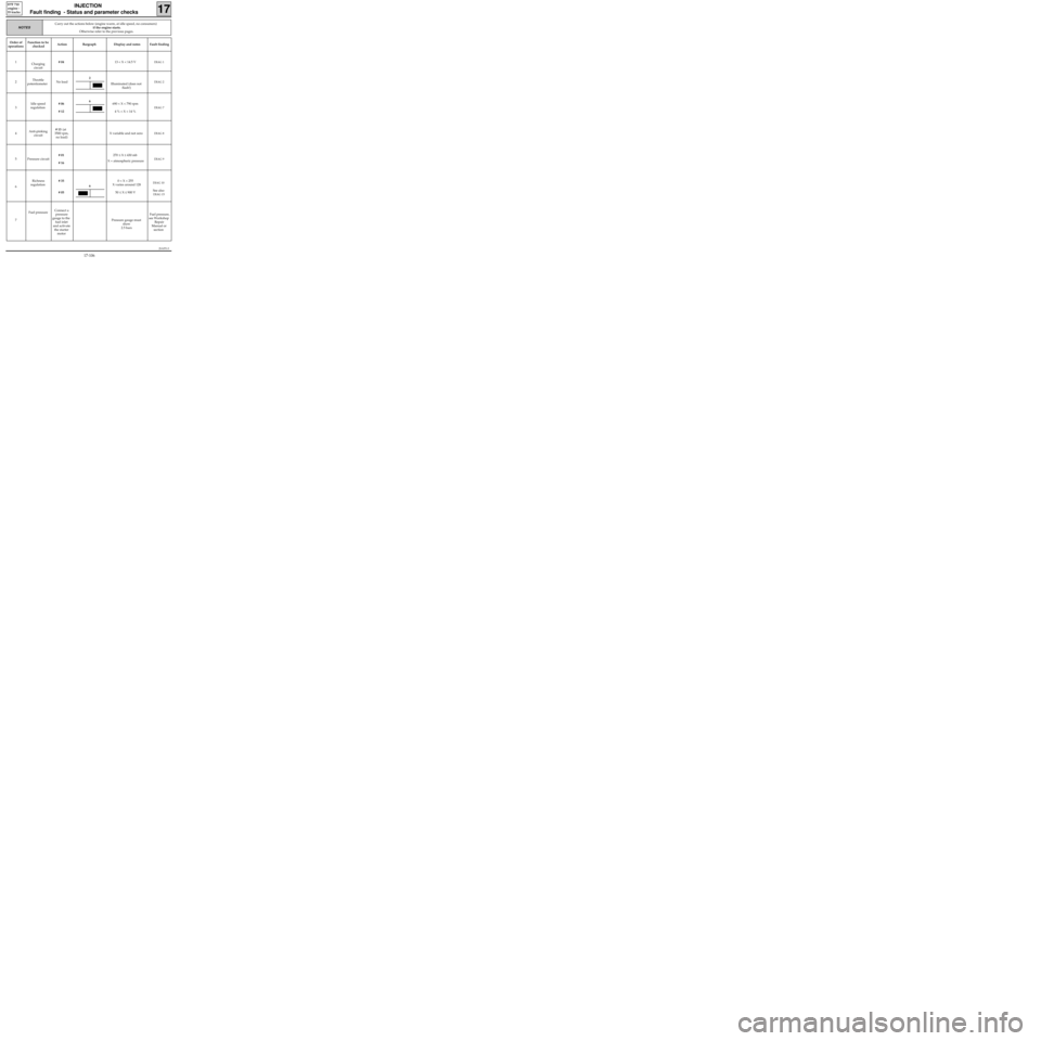
Order of
operationsFunction to be
checkedAction Bargraph Display and notes Fault finding
1
Charging
circuit# 0413 < X < 14.5 V
DIAG 1
2Throttle
potentiometerNo load
Illuminated (does not
flash!)DIAG 2
3Idle speed
regulation# 06
# 12690 < X < 790 rpm
4 % < X < 14 %DIAG 7
4Anti-pinking
circuit# 13 (at
3500 rpm,
no load)X variable and not zeroDIAG 8
5 Pressure circuit# 01
# 16270 ≤ X ≤ 430 mb
X = atmospheric pressureDIAG 9
6Richness
regulation# 35
# 050 < X < 255
X varies around 128
50 ≤ X ≤ 900 V
DIAG 10
See also
DIAG 15
7Fuel pressureConnect a
pressure
gauge to the
fuel inlet
and activate
the starter
motorPressure gauge must
show
2.5 bars Fuel pressure,
see Workshop
Repair
Manual or
section
Carry out the actions below (engine warm, at idle speed, no consumers)
if the engine starts.
Otherwise refer to the previous pages.
NOTES
6
6
2
17-106
Page 152 of 363
JSA051.0
INJECTION
Fault finding - Status and parameter checks
17
D7F 710
engine -
35 tracks
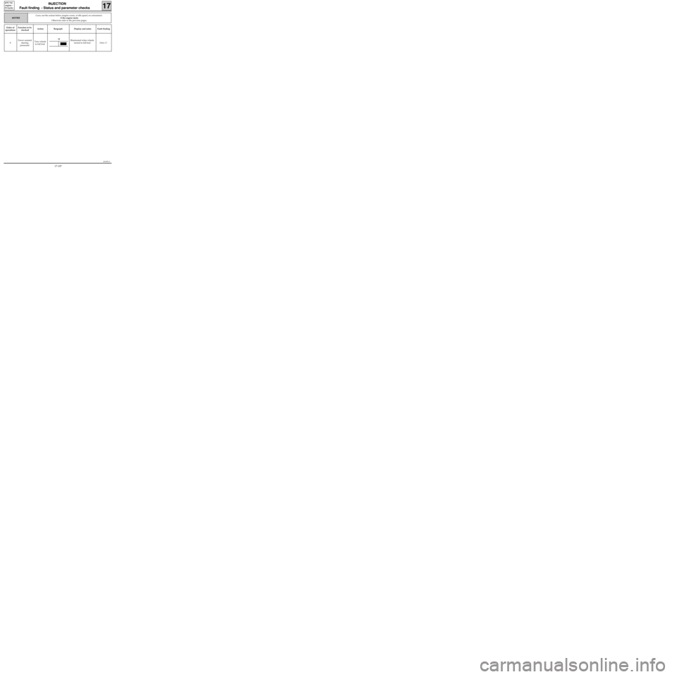
Order of
operationsFunction to be
checkedAction Bargraph Display and notes Fault finding
8Power assisted
steering
pressostatTurn wheels
to full lockIlluminated when wheels
turned to full lock
DIAG 17
Carry out the actions below (engine warm, at idle speed, no consumers)
if the engine starts.
Otherwise refer to the previous pages.
NOTES
13
17-107