check engine RENAULT KANGOO 1997 KC / 1.G Foult Finding - Injection Owner's Manual
[x] Cancel search | Manufacturer: RENAULT, Model Year: 1997, Model line: KANGOO, Model: RENAULT KANGOO 1997 KC / 1.GPages: 363
Page 47 of 363
DPCF01 1.0
LUCAS DIESEL INJECTION
Fault finding - Fault charts
13
Carry out a road test then check using the XR25.AFTER REPAIR
NOTES
Chart 6VEHICLE PRODUCES BLACK SMOKE AT ALTITUDE
Only consult this customer complaint after a complete check using the XR25.
Measure the resistance of the altimetric corrector at the 10 track pump connector (between tracks 1 and
6).
Replace the altimetric corrector if the resistance is not approximately 15 ohms.
Ensure the continuity of the connection between track 1 on the pump connector, wiring side, and track 5
on the altimetric connector control relay (position H on the relay plate in the engine connection unit).
Ensure the presence of earth on track 6 of the pump connector, wiring side.
13-43
Page 48 of 363
E7J 780 ENGINE
MULTIPOINT INJECTION
FAULT FINDING
CONTENTS
Introduction . . . . . . . . . . . . . . . . . . . . . . . . . . . . . . . . . . . . . . . . . . . . . . . . . . . . . . . . . . . . . . . . . . . . . . . . . . . . . . . . . 01
XR25 fiche . . . . . . . . . . . . . . . . . . . . . . . . . . . . . . . . . . . . . . . . . . . . . . . . . . . . . . . . . . . . . . . . . . . . . . . . . . . . . . . . . . . 06
Interpretation of XR25 bargraphs . . . . . . . . . . . . . . . . . . . . . . . . . . . . . . . . . . . . . . . . . . . . . . . . . . . . . . . . . . . . . . 09
Status and parameter checks . . . . . . . . . . . . . . . . . . . . . . . . . . . . . . . . . . . . . . . . . . . . . . . . . . . . . . . . . . . . . . . . . . 30
Status and parameter interpretation . . . . . . . . . . . . . . . . . . . . . . . . . . . . . . . . . . . . . . . . . . . . . . . . . . . . . . . . . . . 36
Customer complaints . . . . . . . . . . . . . . . . . . . . . . . . . . . . . . . . . . . . . . . . . . . . . . . . . . . . . . . . . . . . . . . . . . . . . . . . . 56
Fault charts . . . . . . . . . . . . . . . . . . . . . . . . . . . . . . . . . . . . . . . . . . . . . . . . . . . . . . . . . . . . . . . . . . . . . . . . . . . . . . . . . . 57
Aid . . . . . . . . . . . . . . . . . . . . . . . . . . . . . . . . . . . . . . . . . . . . . . . . . . . . . . . . . . . . . . . . . . . . . . . . . . . . . . . . . . . . . . . . . 62
Checking conformity . . . . . . . . . . . . . . . . . . . . . . . . . . . . . . . . . . . . . . . . . . . . . . . . . . . . . . . . . . . . . . . . . . . . . . . . . 63Page
Page 50 of 363
JF5111.0
INJECTION
Fault finding - Introduction
17
E7J 780
engine
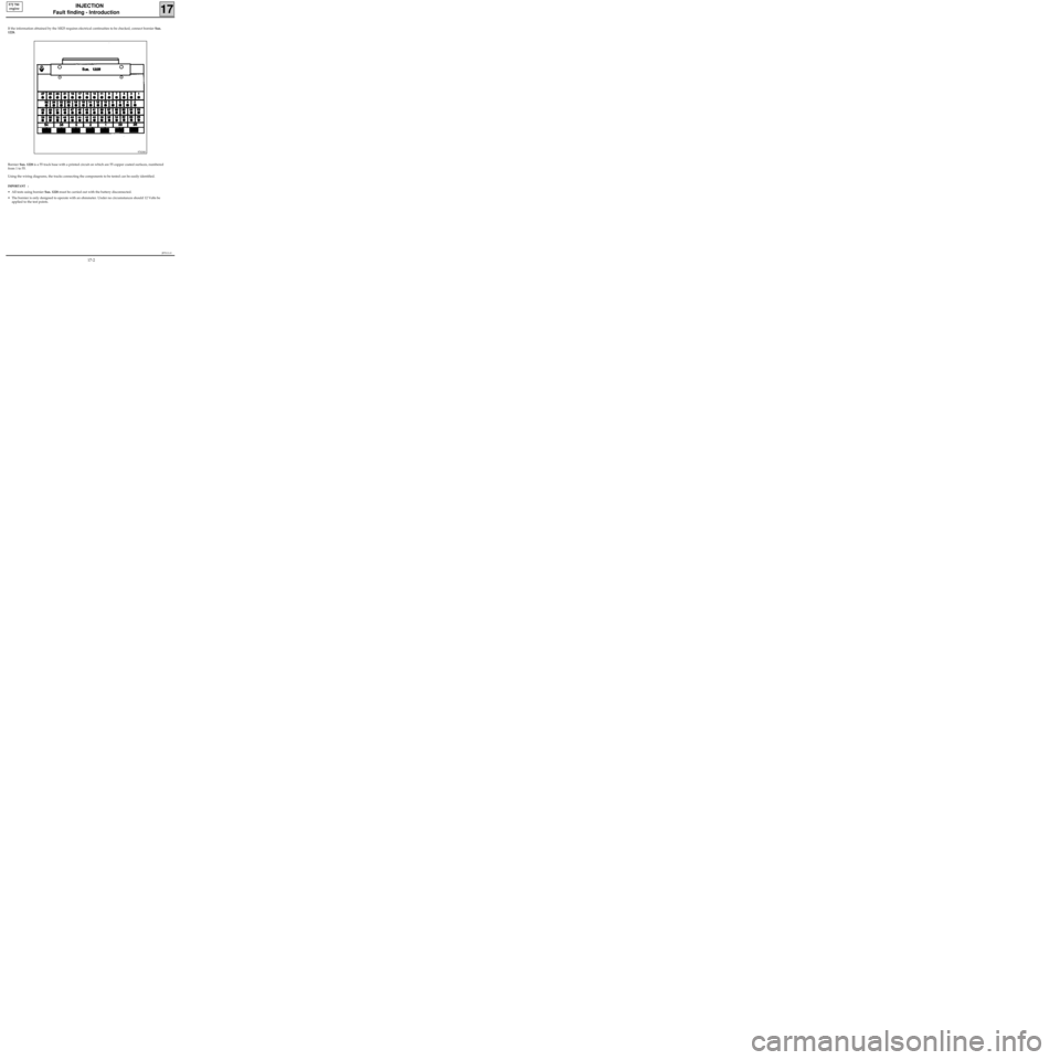
If the information obtained by the XR25 requires electrical continuities to be checked, connect bornier Sus.
1228.
Bornier Sus. 1228 is a 55 track base with a printed circuit on which are 55 copper coated surfaces, numbered
from 1 to 55.
Using the wiring diagrams, the tracks connecting the components to be tested can be easily identified.
IMPORTANT :
• All tests using bornier Sus. 1228 must be carried out with the battery disconnected.
• The bornier is only designed to operate with an ohmmeter. Under no circumstances should 12 Volts be
applied to the test points.
97434S
17-2
Page 51 of 363
JF5111.0
INJECTION
Fault finding - Introduction
17
E7J 780
engine
DESCRIPTION OF THE FAULT-FINDING PHASES
The process described below is to be carried out in all cases of faults.
XR25 FAULT-CHECKING
This phase is the essential starting point for any intervention on the vehicle.
There are several constraints to the treatment of the bargraphs :
- A priority in the order of treatment when several bargraphs are illuminated.
- The interpretation of a bargraph depending on whether it is constantly illuminated or flashing .
1 - Order of priority
A series of illuminated bargraphs corresponding to the sensors with the same 12 V or having the same
earth, indicates a fault in this source. These priorities are dealt with in the "NOTES" section of the
fault-finding of the bargraph concerned.
2 - Input / output fault bargraphs
a) Illuminated :
The fault is present : treat the fault following the method described in the "INTERPRETATION OF XR25
BARGRAPHS" section.
b) Flashing :
Note the bargraphs displayed on the XR25.
Erase the memory of the computer and attempt to re-illuminate the bargraph: ignition on, idle speed
(or at starter speed) or by means of a road test (the "NOTES" section in the fault finding for the
bargraph concerned may help to determine the conditions under which the bargraph will illuminate).
If the bargraph has re-illuminated (fixed or flashing) :
The fault is present once again. In this case, treat the fault bargraph.
If the bargraph has not re-illuminated, check :
- the electrical lines which correspond to the flashing fault,
- the connectors of these lines (for rust, bent pins...).
- the resistance of the component found to be faulty.
- the cleanliness of the wires (insulation melted or cut, friction..).
NOTE : If the customer complaint does not correspond to the fault bargraph which is flashing
(example : Air temperature sensor fault bargraph flashing, but no customer complaint) ignore
this memorised fault and erase it.
3 - No bargraphs illuminated
If no bargraphs are illuminated on the XR25, carry out a status and parameter check. This may help in
detecting a problem.
17-3
Page 52 of 363
JF5111.0
INJECTION
Fault finding - Introduction
17
E7J 780
engine
XR25 CHECKING STATUSES AND PARAMETERS
The status and parameter check is aimed at checking the statuses and parameters which do not illuminate
any fault bargraphs if they are outside of permitted tolerance values . This phase allows :
- Faults to be found without the illumination of fault bargraphs which may correspond to a customer
complaint (example : absence of no load information causing an unstable idle speed).
- The correct operation of the injection to be checked and the risk of faults appearing shortly after the
repair to be eliminated.
This section contains fault-finding for statuses and parameters, under their test conditions
(example : fault finding for # 01 ignition on and fault finding for # 01 engine running).
If a status does not operate normally or a parameter is outside of permitted tolerance values, consult the
fault-finding page indicated in the "Fault-finding" column.
XR25 CHECK CORRECT
If the XR25 check is correct, but the customer complaint persists, the problem must be dealt with through
customer complaints.
Treatment of customer complaints
This section has fault charts, which suggest a series of possible causes of the problem.
These lines of enquiry must only be used in the following cases :
- No fault bargraph appears on the XR25.
- No faults are detected during the checking of statuses and parameters.
- The vehicle is not operating correctly
POST-REPAIR CHECK
This operation is a simple check of the repair (by a command, or by an XR25 command mode ...).
This makes it possible to check that the system upon which the intervention has been carried out is correct
electrically.
It is an introduction to the road test.
ROAD TEST
A road test is essential in order to guarantee the correct operation of the vehicle and to test the quality of the
repair. Its role is to make sure that no faults occur (or will occur) when driving.
In order to be significant, the road test is subject to special driving conditions.
17-4
Page 57 of 363
Connect the bornier in place of the computer and check the insulation and continuity of the line:
Computer 2 Earth
Computer 3 Earth
Computer 11 7 Diagnostic socket
Computer 38 15 Diagnostic socket
Computer 24 Fuse F6 15 A
Computer 32 Fuse F3 5 A
Repair.
JF5111.0
INJECTION
Fault finding - Interpretation of XR25 bargraphs17
E7J 780
engine
Erase the computer memory using G0**.
Try to start the engine. Switch the ignition on, then deal with the other faults.
Remember to carry out a status and parameter check.AFTER REPAIR
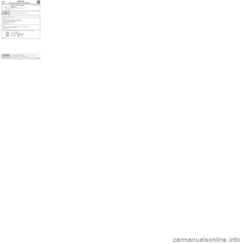
Bargraph 1 RH side extinguishedFiche n° 27 side 1/2
XR25 CIRCUIT
XR25 aid:No connection, CO, CC-, CC+
1
This bargraph must be illuminated for fault findingNOTES
Test the XR25 on another vehicle.
Check:
- the injection, engine and passenger compartment fuses,
- the connection between the XR25 and the diagnostic socket,
- the position of the ISO selector (S8),
- the conformity of the cassette.
Repair if necessary.
Check:
- the presence of + 12 V on track 16 and earth on track 5 of the diagnostic socket,
- that the XR25 cable is in good condition.
Repair if necessary.
17-9
Page 58 of 363
JF5111.0
INJECTION
Fault finding - Interpretation of XR25 bargraphs17
E7J 780
engine
Erase the computer memory using G0**.
Try to start the engine. Switch the ignition on, then deal with the other faults.
Remember to carry out a status and parameter check.AFTER REPAIR
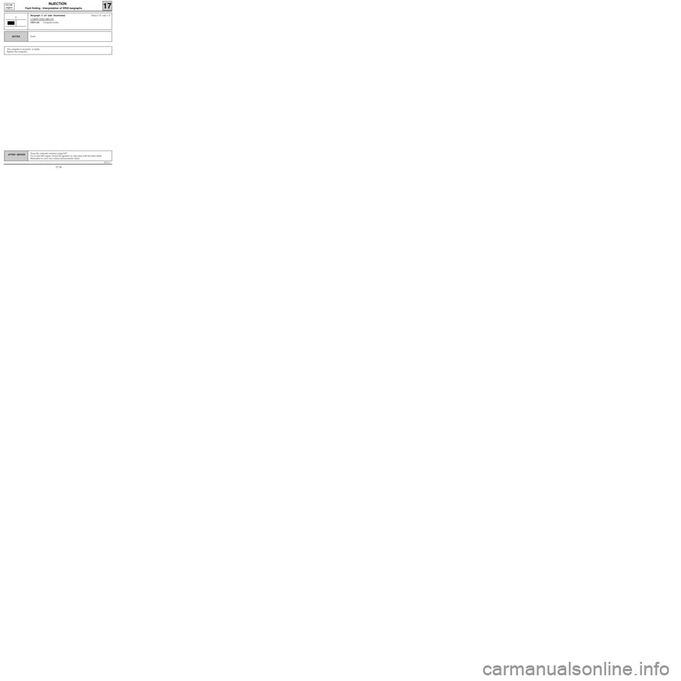
Bargraph 2 LH side illuminatedFiche n° 27 side 1/2
COMPUTER CIRCUIT
XR25 aid:Computer faulty
2
NoneNOTES
The computer is incorrect or faulty.
Replace the computer.
17-10
Page 59 of 363
JF5111.0
INJECTION
Fault finding - Interpretation of XR25 bargraphs17
E7J 780
engine
Erase the computer memory using G0**.
Try to start the engine. Switch the ignition on, then deal with the other faults.
Remember to carry out a status and parameter check.AFTER REPAIR
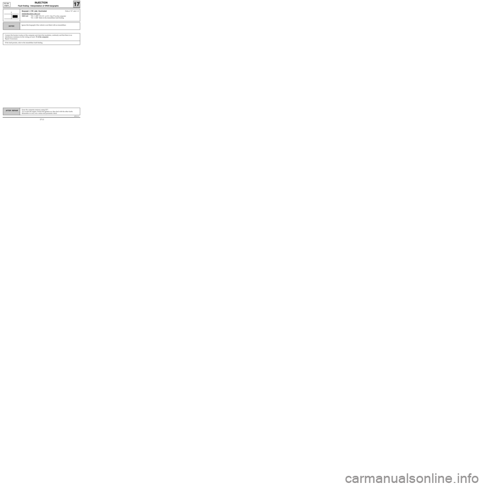
Bargraph 2 RH side illuminatedFiche n° 27 side 1/2
IMMOBILISER CIRCUIT
XR25 aid:*22 = 1 dEF CO, CC- or CC+ line 37 on the computer
*22 = 2 dEF Refer to the immobiliser fault finding
2
Ignore this bargraph if the vehicle is not fitted with an immobiliser.NOTES
Connect the bornier in place of the computer and check the insulation, continuity and that there is no
interference resistance on the wiring on track 37 of the computer.
Repair if necessary.
If the fault persists, refer to the immobiliser fault finding.
17-11
Page 60 of 363
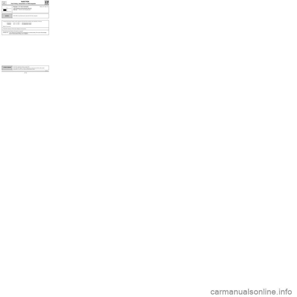
Connect the bornier in place of the computer and check the insulation and continuity of the line:
Computer 20 2 Air temperature sensor
Computer 46 1 Air temperature sensor
Repair if necessary.
JF5111.0
INJECTION
Fault finding - Interpretation of XR25 bargraphs17
E7J 780
engine
Erase the computer memory using G0**.
Try to start the engine. Switch the ignition on, then deal with the other faults.
Remember to carry out a status and parameter check.AFTER REPAIR
Bargraph 3 LH side illuminatedFiche n° 27 side 1/2
AIR TEMPERATURE SENSOR CIRCUIT
XR25 aid:CO, CC- or CC+line 20 or 46
3
If BG 6RH is also illuminated, check line 46 of the computer.NOTES
Check the resistance of the sensor. Replace it if necessary.
The fault persists! Replace the injection computer.
IMPORTANT: The computer has probably been damaged by an electric shock. The cause of the damage
must be found before fitting a new computer.
17-12
Page 61 of 363
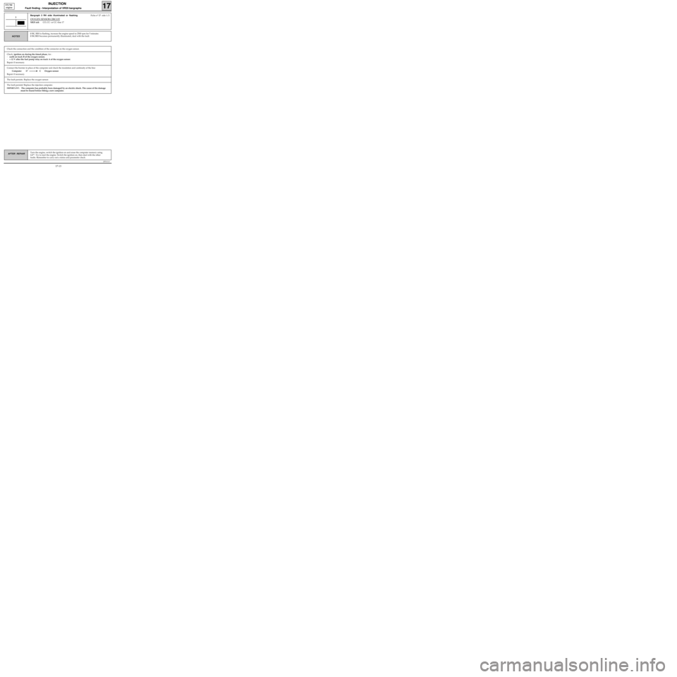
Connect the bornier in place of the computer and check the insulation and continuity of the line:
Computer 17 C Oxygen sensor
Repair if necessary.
JF5111.0
INJECTION
Fault finding - Interpretation of XR25 bargraphs17
E7J 780
engine
Turn the engine, switch the ignition on and erase the computer memory using
G0**. Try to start the engine. Switch the ignition on, then deal with the other
faults. Remember to carry out a status and parameter check.AFTER REPAIR
Bargraph 3 RH side illuminated or flashingFiche n° 27 side 1/2
OXYGEN SENSOR CIRCUIT
XR25 aid:CO, CC- or CC+line 17
3
If BG 3RH is flashing, increase the engine speed to 2500 rpm for 5 minutes
If BG3RH becomes permanently illuminated, deal with the fault.
NOTES
Check the connection and the condition of the connector on the oxygen sensor.
Check, ignition on during the timed phase, for :
-earth on track B of the oxygen sensor,
-+ 12 V after the fuel pump relay on track A of the oxygen sensor.
Repair if necessary.
The fault persists. Replace the oxygen sensor.
The fault persists! Replace the injection computer.
IMPORTANT: The computer has probably been damaged by an electric shock. The cause of the damage
must be found before fitting a new computer.
17-13