ABS RENAULT KANGOO 1997 KC / 1.G Foult Finding - Injection Service Manual
[x] Cancel search | Manufacturer: RENAULT, Model Year: 1997, Model line: KANGOO, Model: RENAULT KANGOO 1997 KC / 1.GPages: 363
Page 292 of 363
B76531.0
ELECTRONICALLY CONTROLLED HYDRAULIC SYSTEM
Fault finding - Fault chart 38
ABS BOSCH
5.3
AFTER REPAIR Carry out a road test, then a check with the XR25 kit.
SPONGY PEDALFault chart 11
Presence of air in the brake circuits.
Bleed the circuits in the conventional way starting with the rear right, then rear left , front left then front
right.
Repeat the operation if necessary.
Only consult this section after a complete check with the XR25 kit.NOTES
38-31
Page 293 of 363
B76531.0
ELECTRONICALLY CONTROLLED HYDRAULIC SYSTEM
Fault finding - Fault chart 38
ABS BOSCH
5.3
AFTER REPAIR Carry out a road test, then a check with the XR25 kit.
BRAKE PEDAL VIBRATIONFault chart 12
Normal reaction of the brake pedal during an ABS regulation phase.
Only consult this section after a complete check with the XR25 kit.NOTES
38-32
Page 294 of 363
B76531.0
ELECTRONICALLY CONTROLLED HYDRAULIC SYSTEM
Fault finding - Fault chart 38
ABS BOSCH
5.3
AFTER REPAIR Carry out a road test, then a check with the XR25 kit.
NOISE FROM THE PUMP, PIPES OR HYDRAULIC ASSEMBLYFault chart 13
- Assembly vibration: check the presence and condition of the rubber assembly mounting pads.
- Vibration of pipes : check that all pipes are well clipped into their fixing clips and that there is no contact
between pipes or between pipes and bodywork.
To determine the origin of the noise, it is possible to use functions G03*, G04*, G05* and G06* on the XR25
kit (consult section "Aid").
Only consult this section after a complete check with the XR25 kit.NOTES
38-33
Page 295 of 363
B76531.0
ELECTRONICALLY CONTROLLED HYDRAULIC SYSTEM
Fault finding - Fault chart 38
ABS BOSCH
5.3
AFTER REPAIR Carry out a road test, then a check with the XR25 kit.
ABS WARNING LIGHT DOES NOT ILLUMINATE,
COMPUTER DISCONNECTEDFault chart 14
Disconnect the ABS computer .
Check if the shunt is present between track 19 and track 21 of the computer connector.
Only consult this section after a complete check with the XR25 kit.NOTES
38-34
Page 296 of 363
B76531.0
ELECTRONICALLY CONTROLLED HYDRAULIC SYSTEM
Fault finding - Fault chart 38
ABS BOSCH
5.3
AFTER REPAIR Carry out a road test, then a check with the XR25 kit.
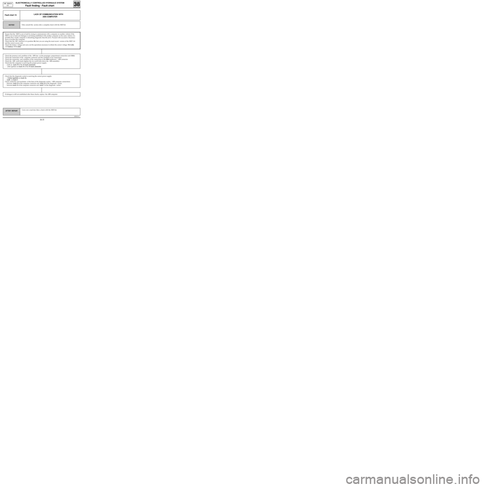
LACK OF COMMUNICATION WITH
ABS COMPUTERFault chart 15
Only consult this section after a complete check with the XR25 kit.NOTES
If dialogue is still not established after these checks, replace the ABS computer.
Check that the diagnostic socket is receiving the correct power supply:
-+ before ignition on track 16,
-earth on track 5.
Check continuity and insulation of the lines of the diagnostic socket / ABS computer connections:
- between track 12 of the computer connector and track 15 of the diagnostic socket,
- between track 11 of the computer connector and track 7 of the diagnostic socket.
Check the presence and condition of the ABS fuse on the passenger compartment connection unit (10A).
Check the connection of the computer connector and the condition of its connections.
Check the connection and condition of the connections at the R36 dashboard / ABS connector.
Check the ABS earth leads (tighten the two earth bolts above the ABS assembly).
Check that the computer is receiving the proper power supply :
- earth on track 19 of the 31 track connector,
- +after ignition on track 15 of the 31 track connector.
Ensure that the XR25 is not at fault by trying to communicate with a computer on another vehicle. If the
XR25 is not at fault and dialogue is not being established with another computer on the same vehicle, it is
possible that a faulty computer is disturbing diagnostic lines K and L. Proceed with successive disconnec-
tions to localise this computer.
Check that the ISO interface is in position S8, that you are using the most recent version of the XR25 kit
and the correct access code.
Check the battery voltage and carry out the operations necessary to obtain the correct voltage (9.4 volts
< U battery< 17.4 volts).
38-35
Page 338 of 363
v0406.0
IMMOBILISER
Fault finding - Aid
82
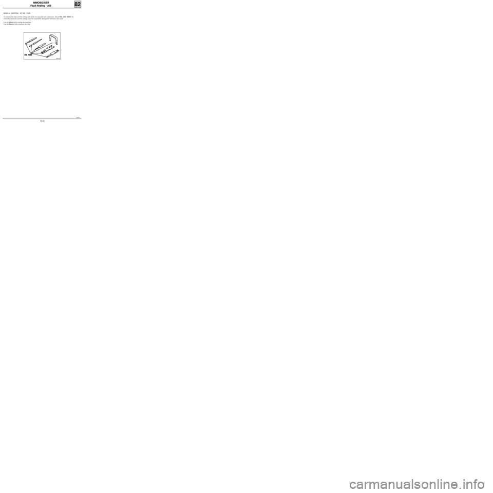
REMOVAL- REFITTING OF THE CLIPS
To remove the clips and the wiring tabs of the two decoder unit connectors, the kit Elé. 1263 MUST be
used.The connector and the wiring could be irreparably damaged if this tool is not used.
Use the black tool to unclip the modules.
Use the brown tool to remove the clips.
96031R
82-41
Page 345 of 363
1EC761.0
AIRBAG - SEAT BELT PRETENSIONERS
Fault finding - XR25 fiche
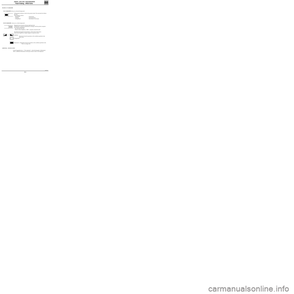
MEANING OF BARGRAPHS
FAULT BARGRAPHS
(always on coloured background)
If illuminated, indicates a fault on the product tested. The associated text defines
the fault.
This bargraph could be :
- Illuminated : fault present.
- Flashing : fault memorised.
- Extinguished : fault absent or not found.
STATUS BARGRAPHS (always on a white background)
Bargraph always located on the top right hand side
If illuminated , indicates establishment of dialogue with the product computer.
If it remains extinguished :
- The code does not exist.
- There is a tool, computer or XR25 / computer connection fault.
The following bargraph representations indicate their initial status :
Initial status: (ignition on, engine stopped, no operator action)
Indefinite
illuminated when the operation or the condition specified on the
fiche is met.
Extinguished
Illuminated extinguished when the operation or the condition specified on the
fiche is no longer met.
ADDITIONAL SPECIFICATIONS
Certain bargraphs have a *. The command *.., when the bargraph is illuminated,
allows additional information on the type of fault or status to be displayed.
or
88
88-6