air conditioning RENAULT KANGOO 1997 KC / 1.G Foult Finding - Injection Workshop Manual
[x] Cancel search | Manufacturer: RENAULT, Model Year: 1997, Model line: KANGOO, Model: RENAULT KANGOO 1997 KC / 1.GPages: 363
Page 30 of 363
DPCF01 1.0
LUCAS DIESEL INJECTION
Fault finding - Interpretation of XR25 bargraphs13
AFTER REPAIRErase the computer memory (G0**), switch the ignition off, then carry out a road
test.
Finish the operation by checking using the XR25.
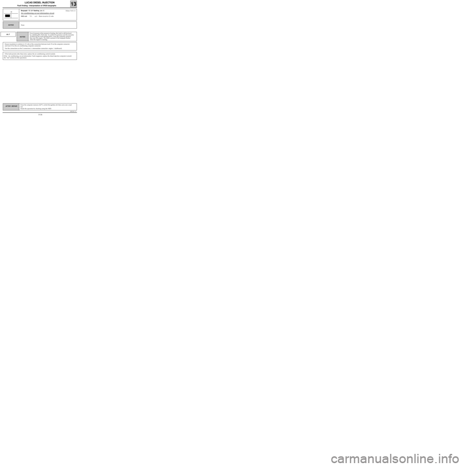
Bargraph 13 LH flashing (cc.1)
Air conditioning cut out information circuit
XR25 aid:*13 :cc.1 : Short circuit to 12 volts
13
None NOTES
Fiche n° 60 1/2
cc.1
Ensure insulation in relation to 12 volts of the connection between track 19 on the computer connector
and track 18 on the air conditioning computer connector.
Test the connections on the 2 connectors (+ intermediate connection engine / dashboard).
Even if present at the moment of testing, this fault is still declared
by a flashing BG 13LH side. To confirm its presence and the necessity
of following the fault finding below, erase the computer memory
then start the engine. The fault is present if the bargraph flashes
when the engine is running.
NOTES
If the fault persists after these tests, replace the air conditioning control module.
If the "air conditioning cut out information "fault reappears, replace the diesel injection computer (consult
the "Aid" section for this operation).
13-26
Page 32 of 363
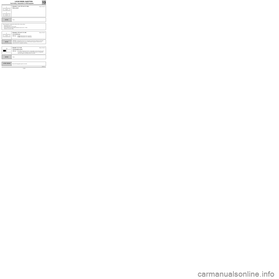
Bargraphs 9 RH and 9 LH side
Air conditioning
XR25 aid :BG 9LH illuminated if AC requested
BG 9RH illuminated if AC authorised
DPCF01 1.0
LUCAS DIESEL INJECTION
Fault finding - Interpretation of XR25 bargraphs13
AFTER REPAIR
Bargraphs 5 and 6 RH and LH sides
Relay control5
None NOTES
These bargraphs visualise the control of the various relays:
- Preheating relay N° 1.
- Preheating relay N° 2 (not used).
- Power assisted steering pump assembly relay (for AC + PAS).
- Altimetric corrector relay.
Fiche n° 60 2/2
6
Ensure the bargraphs operate correctly
9Fiche n° 60 2/2
If
BG 9LH is extinguished when AC is requested, ensure the continuity and insula-
tion of the connection between track 11 of the diesel computer connector and
track 20 of the AC computer connector.
NOTES
Bargraph 10 LH side
Warning light control
XR25 aid :BG 10LH is illuminated if the warning light on the instrument panel
is controlled. This bargraph is normally illuminated; it extinguishes
when the engine is running if there is no fault.
10Fiche n° 60 2/2
None
NOTES
13-28
Page 34 of 363
DPCF01 1.0
LUCAS DIESEL INJECTION
Fault finding - Interpretation of XR25 bargraphs13
AFTER REPAIR
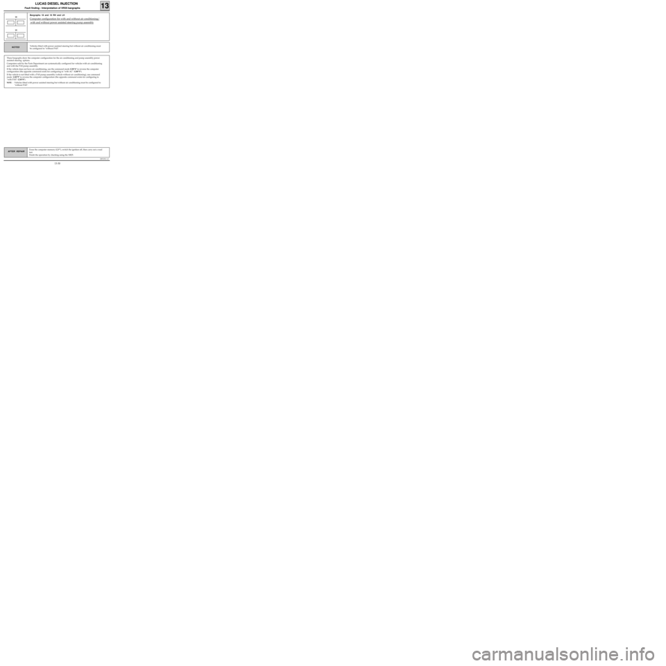
Bargraphs 18 and 19 RH and LH
Computer configuration for with and without air conditioning/
with and without power assisted steering pump assembly
18
Vehicles fitted with power assisted steering but without air conditioning must
be configured to "without PAS".NOTES
These bargraphs show the computer configuration for the air conditioning and pump assembly power
assisted steering options.
Computers sold by the Parts Department are systematically configured for vehicles with air conditioning
and with the PAS pump assembly.
If the vehicle does not have air conditioning, use the command mode G50*4* to reverse the computer
configuration (the opposite command exists for configuring to "with AC": G50*3*).
If the vehicle is not fitted with a PAS pump assembly (vehicle without air conditioning), use command
mode G50*9* to reverse the computer configuration (the opposite command exists for configuring to
"with PAS": G50*8*).
NOTE : Vehicles fitted with power assisted steering but without air conditioning must be configured to
"without PAS".
19
Erase the computer memory (G0**), switch the ignition off, then carry out a road
test.
Finish the operation by checking using the XR25.
13-30
Page 35 of 363
DPCF01 1.0
LUCAS DIESEL INJECTION
Fault finding - Aid
13
REPLACING THE COMPUTER
A)On these computers it is necessary to programme the load lever full load position (this value is required to
replace and adjust the load lever position potentiometer).
Programming procedure:
• Enter code G31* on the XR25 (engine speed zero)
• Press the accelerator pedal until the display flashes
"PF".
The display then shows "bon", "Fin" then "6/7.dlE" when the procedure has been carried out correctly.
Bargraph 12 RH side must be extinguished.
• Switch off the ignition.
B)Lucas digital DPC injection computers are sold pre-configured to "with air conditioning".
If the vehicle does not have air conditioning, use command G50*4* on the XR25 to programme "without
air conditioning".
Lucas digital DPC injection computers are sold pre-configured to "with power assisted steering" (with po-
wer assisted steering pump assembly).
If the vehicle does not have a power assisted steering pump assembly (vehicle without air conditioning),
use command G50*9* on the XR25 to programme "without power assisted steering".
Vehicles fitted with power assisted steering but without air conditioning must be configured to "without
power assisted steering".
REPLACING THE LOAD LEVER POSITION POTENTIOMETER
The load lever position potentiometer may only be replaced in After Sales if the full load position has been
programmed into the computer before the fault with the potentiometer.
Procedure for replacing and adjusting the load lever position potentiometer:
• Fit the new potentiometer into position without locking the mounting bolts.
• Connect the potentiometer and set up the XR25 (S8 code D34).
• Start command G32* on the XR25, keep the accelerator pedal fully depressed (do not touch the load lever
directly) and turn the potentiometer until the display on the XR25 shows a value other than H.L (outside li-
mits). Adjust the setting by turning the potentiometer to obtain 0 on the display.
• Tighten the mounting bolts with the potentiometer in this position then press * to complete the adjus-
tment procedure.
13-31
Page 38 of 363
DPCF01 1.0
LUCAS DIESEL INJECTION
Fault finding - Checking conformity
13
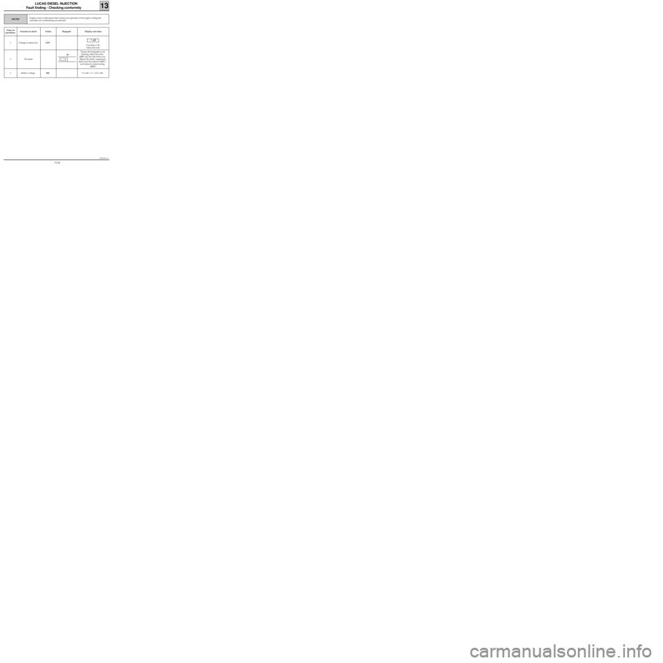
Order of
operationsFunction to check Action Bargraph Display and notes
1 Change to status testG01* 7. dlE
Use fiche n° 60
status test side
2 No faultsEnsure this bargraph is not
flashing, otherwise enter
G02* and turn the fiche over.
Repair the faulty component
then erase the memory (G0**)
and return to status testing
(G01*)
3 Battery voltage#04 13 volts < X < 14.5 volts
Engine warm at idle speed after at least one operation of the engine cooling fan
assembly (air conditioning not selected).NOTES
20
13-34
Page 39 of 363
DPCF01 1.0
LUCAS DIESEL INJECTION
Fault finding - Checking conformity
13
Engine warm at idle speed after at least one operation of the engine cooling fan
assembly (air conditioning not selected).NOTES
Order of
operationsFunction to check Action Bargraph Display and notes
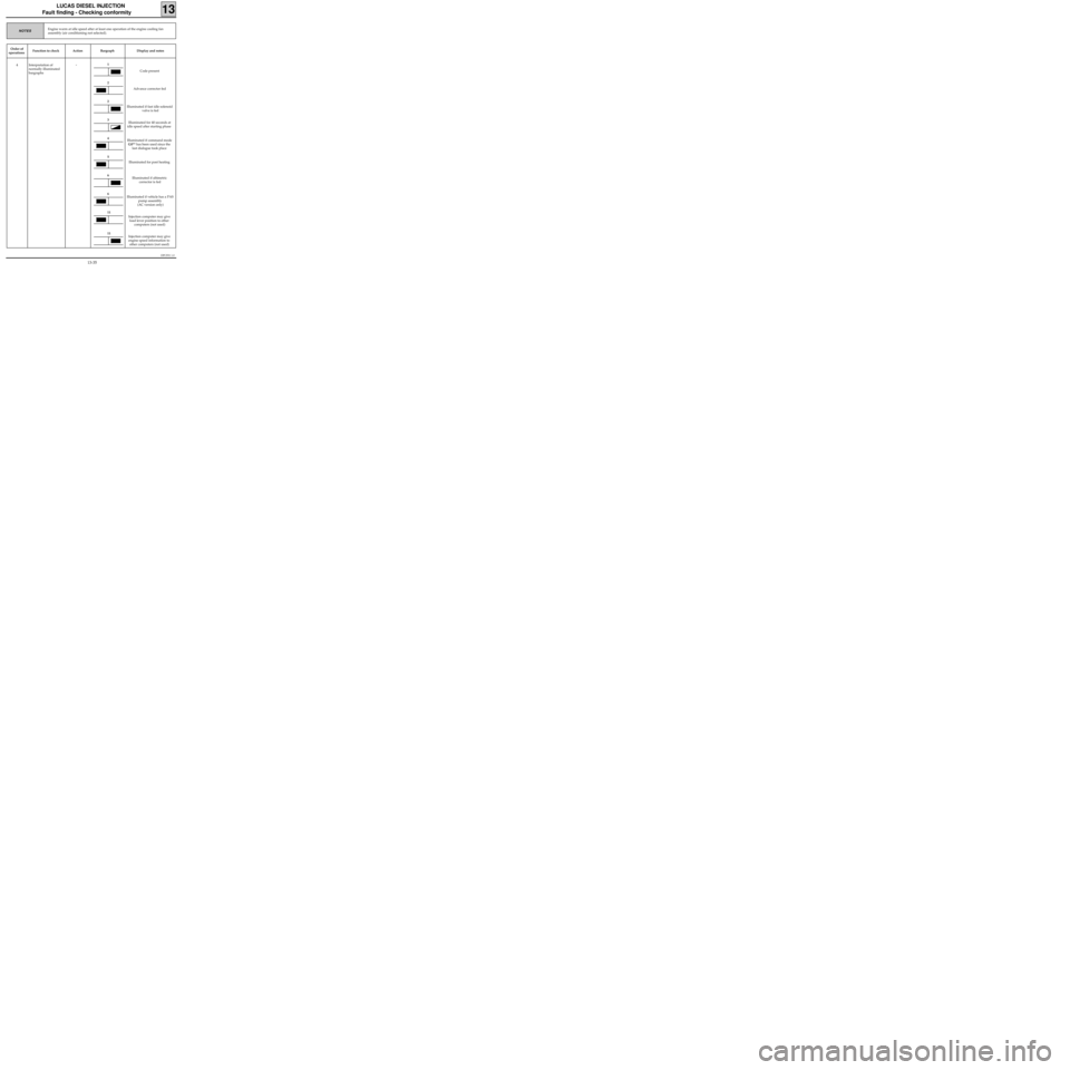
4 Interpretation of
normally illuminated
bargraphs
-
Code present
Advance corrector fed
Illuminated if fast idle solenoid
valve is fed
Illuminated for 40 seconds at
idle speed after starting phase
Illuminated if command mode
G0** has been used since the
last dialogue took place
Illuminated for post heating
Illuminated if altimetric
corrector is fed
Illuminated if vehicle has a PAS
pump assembly
(AC version only)
Injection computer may give
load lever position to other
computers (not used)
Injection computer may give
engine speed information to
other computers (not used)1
2
2
3
4
5
6
6
11
11
13-35
Page 40 of 363
DPCF01 1.0
LUCAS DIESEL INJECTION
Fault finding - Checking conformity
13
Engine warm at idle speed after at least one operation of the engine cooling fan
assembly (air conditioning not selected).NOTES
Order of
operationsFunction to check Action Bargraph Display and notes
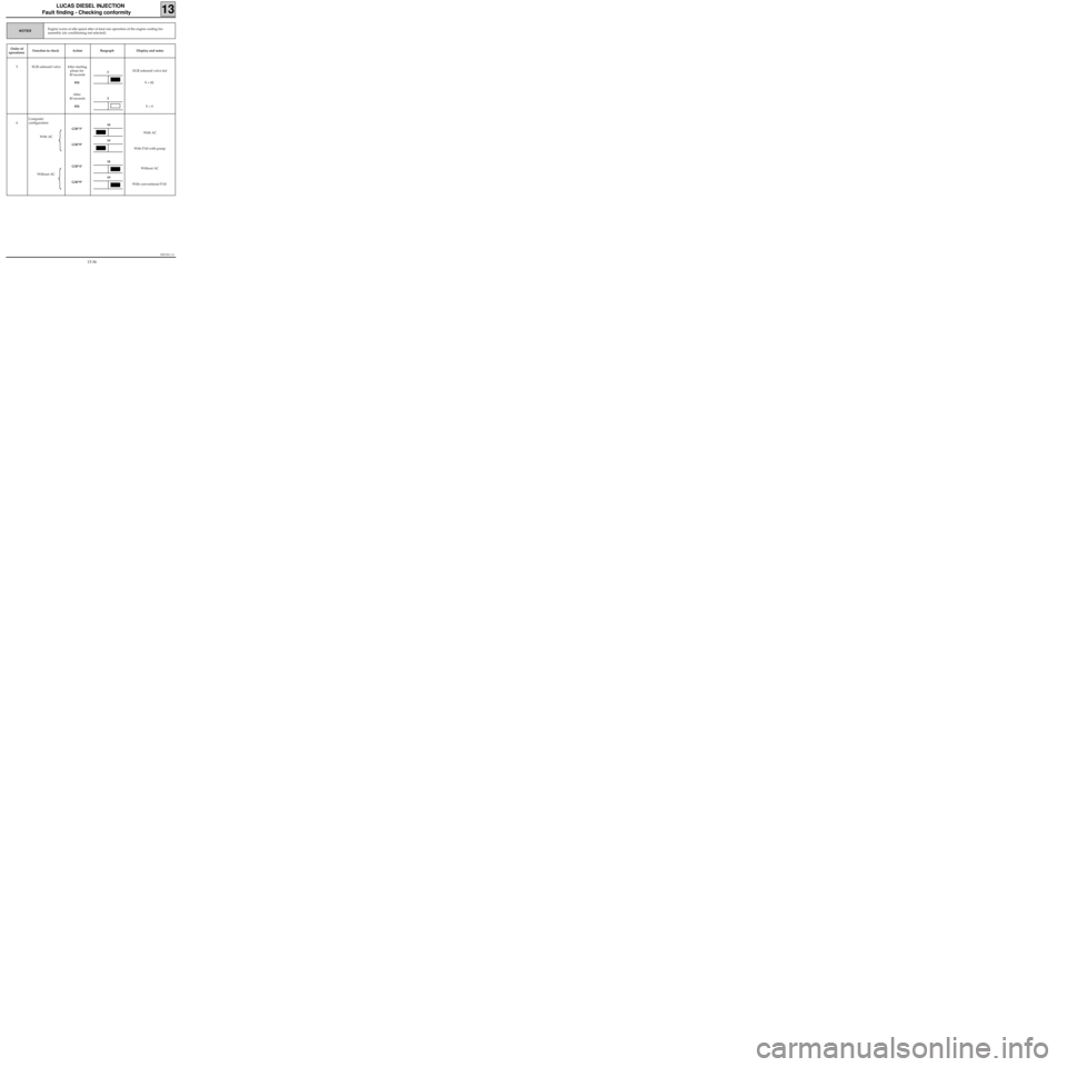
5 EGR solenoid valve After starting
phase for
40 seconds
#24
After
40 seconds
#24EGR solenoid valve fed
X = 82
X = 0
6Computer
configuration
With AC
Without ACG50*3*
G50*8*
G50*4*
G50*9*With AC
With PAS with pump
Without AC
With conventional PAS
3
3
18
18
19
19
13-36
Page 41 of 363
DPCF01 1.0
LUCAS DIESEL INJECTION
Fault finding - Customer complaints
13
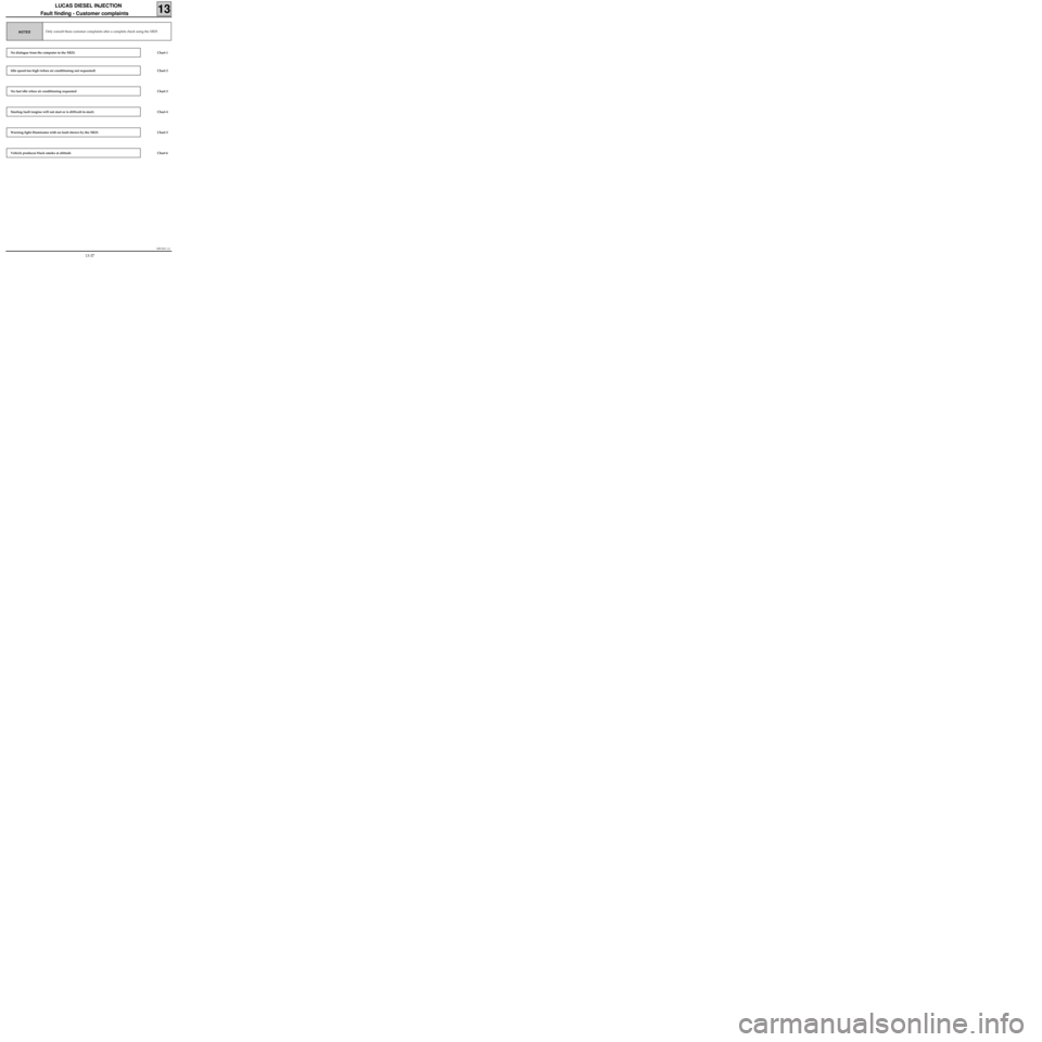
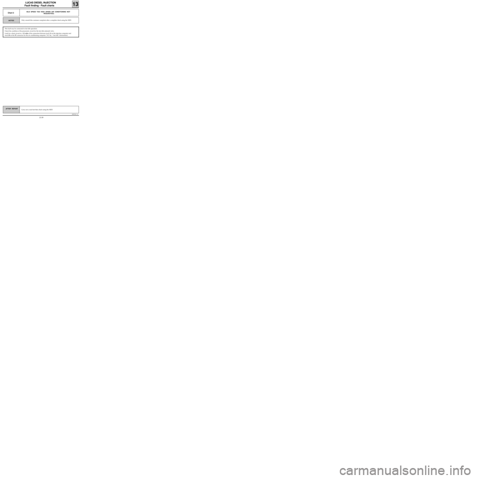
Only consult these customer complaints after a complete check using the XR25.NOTES
No dialogue from the computer to the XR25.
Idle speed too high (when air conditioning not requested)
No fast idle when air conditioning requested
Starting fault (engine will not start or is difficult to start).
Warning light illuminates with no fault shown by the XR25.
Vehicle produces black smoke at altitude
Chart 1
Chart 2
Chart 3
Chart 4
Chart 5
Chart 6
13-37
Page 43 of 363
DPCF01 1.0
LUCAS DIESEL INJECTION
Fault finding - Fault charts
13
Carry out a road test then check using the XR25.AFTER REPAIR
Only consult this customer complaint after a complete check using the XR25.NOTES
Chart 2IDLE SPEED TOO HIGH (WHEN AIR CONDITIONING NOT
REQUESTED)
This fault may be connected to fast idle operation.
Check the condition of the pneumatic circuit for the fast idle solenoid valve.
Look for a short circuit to + 12 volts of the connection between track 11 on the injection computer and
track 20 on the BE connector for the air conditioning computer ("AC Inj. / fast idle" information).
13-39
Page 44 of 363
DPCF01 1.0
LUCAS DIESEL INJECTION
Fault finding - Fault charts
13
Carry out a road test then check using the XR25.AFTER REPAIR
NOTES
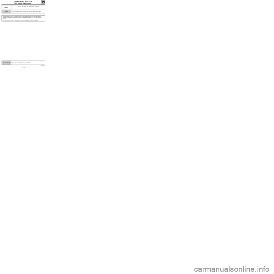
Chart 3NO FAST IDLE WHEN AIR CONDITIONING REQUESTED
Only consult this customer complaint after a complete check using the XR25.
Look for an open circuit or a short circuit to earth on the connection between track 11 on the injection
computer and track 20 on the BE connector for the air conditioning computer ("AC Inj. / fast idle" infor-
mation).
This fault causes the absence of illumination of bargraph 9 LH side "air conditioning requested".
13-40