fuel RENAULT KANGOO 1997 KC / 1.G Foult Finding - Injection Workshop Manual
[x] Cancel search | Manufacturer: RENAULT, Model Year: 1997, Model line: KANGOO, Model: RENAULT KANGOO 1997 KC / 1.GPages: 363
Page 18 of 363
DPCF01 1.0
LUCAS DIESEL INJECTION
Fault finding - Interpretation of XR25 bargraphs13
AFTER REPAIRErase the computer memory (G0**), switch the ignition off, then carry out a road
test.
Finish the operation by checking using the XR25.
Bargraph 5 LH flashing
Needle lift sensor circuit
5
The needle lift sensor circuit fault is present if the bargraph illuminates when the
engine is running. Use bornier Elé. 1332 for any operations on the computer
connector.
NOTES
Measure the resistance of the needle lift sensor at its connector.
Replace the injector with the sensor if the resistance is not approximately 105 ohms.
Ensure the continuity of the following connections:
- Between track 7 on the computer connector and track 1 on the needle lift sensor connector.
- Between track 3 on the computer connector and track 2 on the needle lift sensor connector.
Test the connections on the 2 connectors.
Fiche n° 60 1/2
Ensure the insulation of the connection between track 7 on the computer connector and track 1 on the
needle lift sensor connector .
Also ensure the insulation between the 2 lines on the needle lift sensor.
Also check the condition of the wiring between the sensor connector and the sensor.
If the fault persists after these tests, replace the injector with the sensor.
If the "needle lift sensor circuit" fault reappears, replace the computer (consult the "Aid" section for this
operation).
The "needle lift sensor circuit" fault may be connected to absence of injection at the cylinder with the
sensor.
Check the condition of the injector and its fuel supply.
13-14
Page 21 of 363
DPCF01 1.0
LUCAS DIESEL INJECTION
Fault finding - Interpretation of XR25 bargraphs13
AFTER REPAIRErase the computer memory (G0**), switch the ignition off, then carry out a road
test.
Finish the operation by checking using the XR25.
1.dEF
This fault indicates that the advance corrector is seized, the injection pump has been incorrectly set or
there is a fuel supply fault.
It is taken into account when the advance noted by the needle lift sensor differs by more than 5° from the
advance value requested by the computer.
NOTE : If there is a fault where the advance corrector is seized, there will be a characteristic noise when
the ignition is switched on (irregular clicking of the corrector).
The fault is present if the bargraph is illuminated when the engine is
running.NOTES
6
CONT
- Check the condition of the fuel supply to the pump and the injectors (filter blocked, pipe kinked, air
leak, ...).
Check the type of diesel fuel used in extreme cold weather (a "summer " type diesel fuel may cause
this fault at -15 °C).
- Check the pump timing and check the tightness of the pump pulley.
- If the fuel supply and the pump timing are correct, replace the advance corrector.
13-17
Page 45 of 363
DPCF01 1.0
LUCAS DIESEL INJECTION
Fault finding - Fault charts
13
Carry out a road test then check using the XR25.AFTER REPAIR
If the fault persists, check the fuel supply circuits (for the pump and the injectors).
If necessary, carry out a complete check of the engine (starter drive speed, pump timing, condition of
injectors, rocker arm clearances, compression, .....).NOTES
Chart 4STARTING FAULT (ENGINE WILL NOT START OR IS DIFFICULT TO
START) (warning light extinguished).
Only consult this customer complaint after a complete check using the XR25.
If no fault is shown by the XR25, ensure that the fault is not caused by a faulty immobiliser system.
Check the operation of the preheating system:
Start command mode G10*1* and check for a voltage at the plugs.
If the plugs are not fed, check the connection of the 3 track connector on the relay unit and the condition
of the 70 Amp fuse on the engine connection unit.
13-41
Page 61 of 363
Connect the bornier in place of the computer and check the insulation and continuity of the line:
Computer 17 C Oxygen sensor
Repair if necessary.
JF5111.0
INJECTION
Fault finding - Interpretation of XR25 bargraphs17
E7J 780
engine
Turn the engine, switch the ignition on and erase the computer memory using
G0**. Try to start the engine. Switch the ignition on, then deal with the other
faults. Remember to carry out a status and parameter check.AFTER REPAIR
Bargraph 3 RH side illuminated or flashingFiche n° 27 side 1/2
OXYGEN SENSOR CIRCUIT
XR25 aid:CO, CC- or CC+line 17
3
If BG 3RH is flashing, increase the engine speed to 2500 rpm for 5 minutes
If BG3RH becomes permanently illuminated, deal with the fault.
NOTES
Check the connection and the condition of the connector on the oxygen sensor.
Check, ignition on during the timed phase, for :
-earth on track B of the oxygen sensor,
-+ 12 V after the fuel pump relay on track A of the oxygen sensor.
Repair if necessary.
The fault persists. Replace the oxygen sensor.
The fault persists! Replace the injection computer.
IMPORTANT: The computer has probably been damaged by an electric shock. The cause of the damage
must be found before fitting a new computer.
17-13
Page 68 of 363
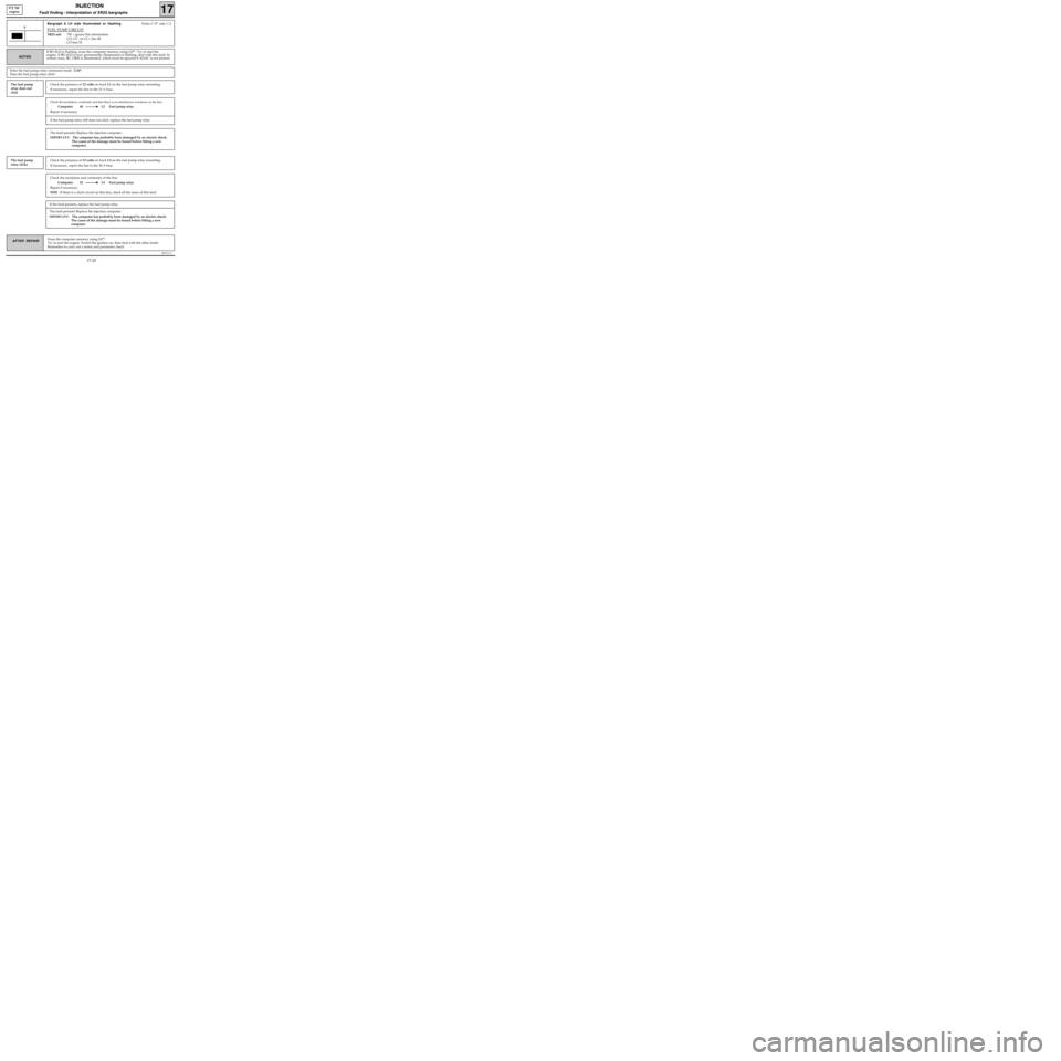
Check the insulation and continuity of the line:
Computer 52 L5 Fuel pump relay
Repair if necessary.
NOTE : If there is a short circuit on this line, check all the users of this feed.
Check the insulation, continuity and that there is no interference resistance on the line:
Computer 48 L2 Fuel pump relay
Repair if necessary.
JF5111.0
INJECTION
Fault finding - Interpretation of XR25 bargraphs17
E7J 780
engine
Erase the computer memory using G0**.
Try to start the engine. Switch the ignition on, then deal with the other faults.
Remember to carry out a status and parameter check.AFTER REPAIR
Bargraph 8 LH side illuminated or flashingFiche n° 27 side 1/2
FUEL PUMP CIRCUIT
XR25 aid:*08 = ignore this information
CO, CC- or CC+ line 48
CO line 52
8
NOTES
The fault persists! Replace the injection computer.
IMPORTANT: The computer has probably been damaged by an electric shock.
The cause of the damage must be found before fitting a new
computer.
If the fuel pump relay still does not click, replace the fuel pump relay.
If BG 8LH is flashing, erase the computer memory using G0**. Try to start the
engine. If BG 6LH is now permanently illuminated or flashing, deal with this fault. In
certain cases, BG 13RH is illuminated, which must be ignored if ADAC is not present.
Enter the fuel pump relay command mode : G10*.
Does the fuel pump relay click?
The fuel pump
relay does not
clickCheck the presence of 12 volts on track L1 on the fuel pump relay mounting.
If necessary, repair the line to the 15 A fuse.
The fault persists! Replace the injection computer.
IMPORTANT: The computer has probably been damaged by an electric shock.
The cause of the damage must be found before fitting a new
computer.
If the fault persists, replace the fuel pump relay.
The fuel pump
relay clicksCheck the presence of 12 volts on track L3 on the fuel pump relay mounting.
If necessary, repair the line to the 30 A fuse.
17-20
Page 69 of 363
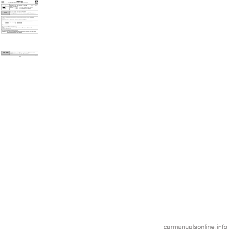
Connect the bornier in place of the computer and check the insulation and continuity of the line :
Computer 30 2 Injectors 1 and 4
Computer 4 2 Injectors 2 and 3
Repair if necessary.
JF5111.0
INJECTION
Fault finding - Interpretation of XR25 bargraphs17
E7J 780
engine
Turn the engine, switch the ignition on and erase the computer memory using
G0**. Try to start the engine. Switch the ignition on, then deal with the other
faults. Remember to carry out a status and parameter check.AFTER REPAIR
Bargraph 11 LH side illuminated or flashingFiche n° 27 side 1/2
INJECTOR CIRCUIT
XR25 aid:*11 = XX.CO=> CO or CC- line 30 or 4 on the computer
*11 = XX.CC=> CC+ line 30 or 4 on the computer
11
XX = 14 => Cylinder 1 or 4 line 30 on the computer
XX = 23 =
> Cylinder 2 or 3 line 4 on the computer
If BG 11LH is flashing, erase the computer memory using G0**. Try to start the
engine. If BG 11LH is now permanently illuminated or flashing, deal with this fault. NOTES
When the ignition is switched on and during the timed phase, check for 12 V on track 1 of the faulty
injector.
If necessary, repair the line from track 1 injector to track L5 fuel pump relay.
The fault persists! Replace the injection computer.
IMPORTANT: The computer has probably been damaged by an electric shock. The cause of the damage
must be found before fitting a new computer.
The fault persists! Replace the faulty injector.
NOTE : Check the insulation and continuity of the lines for the other injectors and also check the
resistance of these injectors.
17-21
Page 72 of 363
JF5111.0
INJECTION
Fault finding - Interpretation of XR25 bargraphs17
E7J 780
engine
Erase the computer memory using G0**.
Try to start the engine. Switch the ignition on, then deal with the other faults.
Remember to carry out a status and parameter check.AFTER REPAIR
Bargraph 13 RH side illuminated or flashingFiche n° 27 side 1/2
ADAC CIRCUIT
XR25 aid:False diagnosis by computer for vehicles not fitted with ADAC
13
This vehicle is not fitted with ADAC at the moment.
If another bargraph is illuminated, refer to the fault finding for that bargraph.NOTES
If your vehicle has ADAC,
this method of fault finding will not be of use for this fault.
This bargraph is often illuminated or flashing in the following cases:
-Air conditioning compressor command mode G12*.
-Fault on fuel pump relay circuit.
-Other cases, which have not yet been noted, may well exist.
17-24
Page 80 of 363
JF5111.0
INJECTION
Fault finding - Status and parameter checks
17
E7J 780
engine
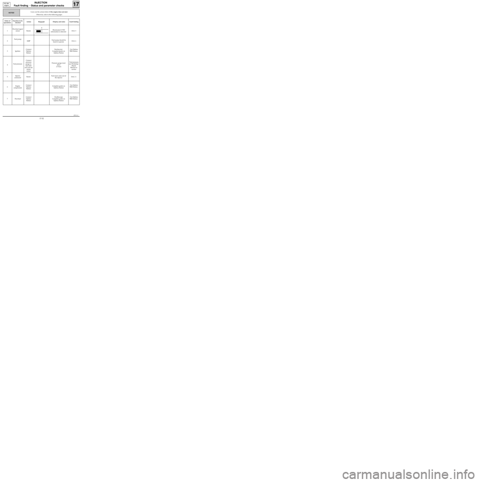
Carry out the actions below if the engine does not start.
Otherwise, refer to the following pages.NOTES
Order of
operationsFunction to be
checkedAction Bargraph Display and notes Fault finding
1Flywheel signal
sensor StarterIlluminated if TDC
information is detected
DIAG 5
2Fuel pump
G10*Fuel pump should be
heard to operateDIAG 6
3 IgnitionConnect
Optima
StationStarting test.
Complete guide on
Optima StationUse Optima
5800 Station
4Fuel pressureConnect
pressure
gauge to
fuel inlet
and activate
starter
motorPressure gauge must
show
2.5 bars Fuel pressure,
see Workshop
Repair
Manual or
section
5Injector
commandStarterFuel must come out of
the injector
DIAG 11
6Engine
compressionConnect
Optima
StationComplete guide on
Optima StationUse Optima
5800 Station
7 FlywheelConnect
Optima
StationOscilloscope.
Complete guide on
Optima StationUse Optima
5800 Station
3
17-32
Page 81 of 363
JF5111.0
INJECTION
Fault finding - Status and parameter checks
17
E7J 780
engine
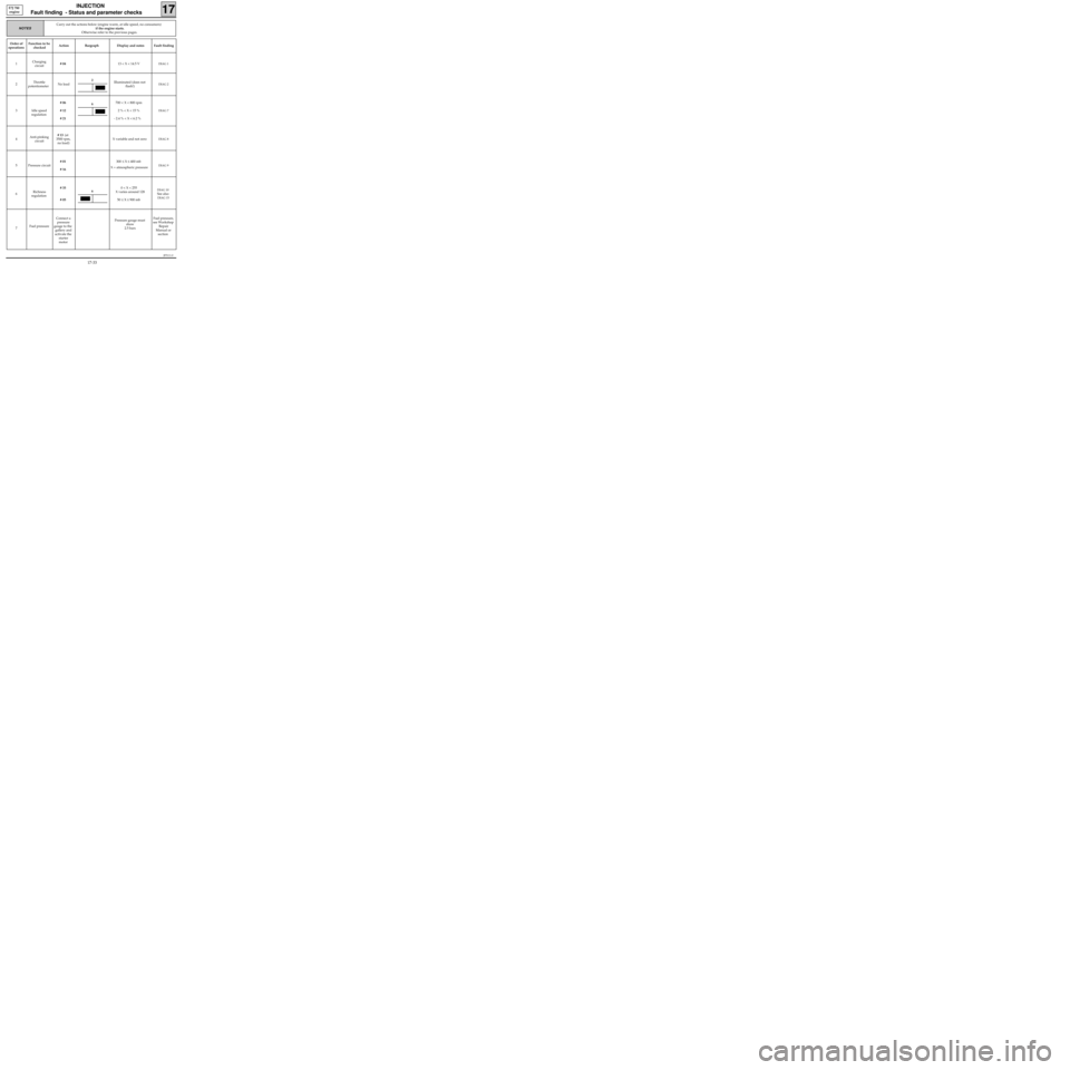
Order of
operationsFunction to be
checkedAction Bargraph Display and notes Fault finding
1Charging
circuit# 0413 < X < 14.5 V
DIAG 1
2Throttle
potentiometerNo loadIlluminated (does not
flash!)DIAG 2
3 Idle speed
regulation# 06
# 12
# 21700 < X < 800 rpm
2 % < X < 15 %
- 2.4 % < X < 6.2 %DIAG 7
4Anti-pinking
circuit# 13 (at
3500 rpm,
no load)X variable and not zeroDIAG 8
5 Pressure circuit# 01
# 16300 ≤ X ≤ 400 mb
X = atmospheric pressureDIAG 9
6Richness
regulation# 35
# 050 < X < 255
X varies around 128
50 ≤ X ≤ 900 mb
DIAG 10
See also
DIAG 15
7Fuel pressureConnect a
pressure
gauge to the
gallery and
activate the
starter
motorPressure gauge must
show
2.5 barsFuel pressure,
see Workshop
Repair
Manual or
section
Carry out the actions below (engine warm, at idle speed, no consumers)
if the engine starts.
Otherwise refer to the previous pages.
NOTES
6
6
2
17-33
Page 89 of 363
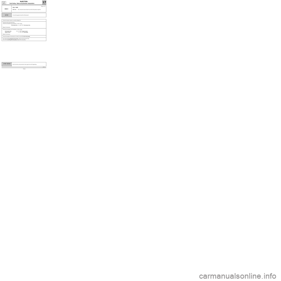
Check the insulation and continuity of the wiring:
Fuel pump relay L5 Impact sensor
Impact sensor C1 Fuel pump
Repair if necessary.
Check the 30A fuel pump fuse.
Check the insulation and continuity of the wiring:
Fuel pump fuse L3 Fuel pump relay
Repair if necessary.
JF5111.0
INJECTION
Fault finding - Status and parameter interpretation17
E7J 780
engine
AFTER REPAIRStart the status and parameter check again from the beginning.
DIAG 6
Fiche n° 27
FUEL PUMP
XR25 aid:The command mode should cause the fuel pump to operate
No fault bargraphs should be illuminated.NOTES
Check the hygiene and presence of earth on track C2 of the fuel pump.
If + 12 V is not reaching the fuel pump, replace the fuel pump relay.
If + 12 V is reaching the fuel pump, replace the fuel pump.
Check the impact sensor is correctly clipped in.
17-41